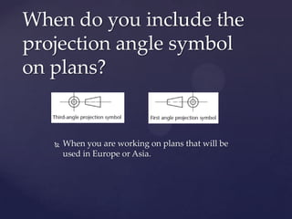
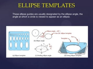
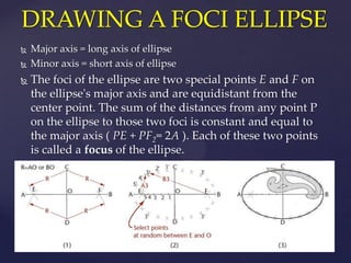
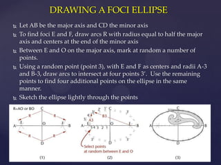
2D Essentials
      Instructor: Laura Gerold, PE
      Catalog #10614113
  {   Class # 22784, 24113, 24136, & 24138
      Class Start: January 18, 2012 Class End:
      May 16, 2012
Questions . . .
When do you include the
projection angle symbol
on plans?


      When you are working on plans that will be
       used in Europe or Asia.
ELLIPSE TEMPLATES
These ellipse guides are usually designated by the ellipse angle, the
angle at which a circle is viewed to appear as an ellipse.
DRAWING A FOCI ELLIPSE
   Major axis = long axis of ellipse
   Minor axis = short axis of ellipse
   The foci of the ellipse are two special points E and F on
    the ellipse's major axis and are equidistant from the
    center point. The sum of the distances from any point P
    on the ellipse to those two foci is constant and equal to
    the major axis ( PE + PF2= 2A ). Each of these two points
    is called a focus of the ellipse.
DRAWING A FOCI ELLIPSE
   Let AB be the major axis and CD the minor axis
   To find foci E and F, draw arcs R with radius equal to half the major
    axis and centers at the end of the minor axis
   Between E and O on the major axis, mark at random a number of
    points.
   Using a random point (point 3), with E and F as centers and radii A-3
    and B-3, draw arcs to intersect at four points 3’. Use the remaining
    points to find four additional points on the ellipse in the same
    manner.
   Sketch the ellipse lightly through the points
Drawing an Ellipse

   Draw a major axis 5” long and a minor axis 2.5” long.
    Draw an ellipse by the foci method with at least five
    points in each quadrant
DRAWING AN ARC TANGENT TO TWO
    LINES AT ACUTE OROBTUSE ANGLES
   Given two lines not making a 90°
   Draw lines parallel to the given lines at distance R from them to
    intersect at C the center
   From C, drop perpendiculars to the given lines to locate tangent
    points, T
   With C as the center and with given radius R, draw the required
    tangent arc between the points of tangency
DRAWING AN ARC TANGENT TO TWO
LINES AT ACUTE OROBTUSE ANGLES


  Draw two intersecting lines at an acute
   angle, each 2.5 inches long
  Draw a 1.5 inch radius arc tangent to the
   two lines
TEST REVIEW
  {
How Many Questions are
on the Test?


   50
   You have the entire class
    period to complete the test
How are the questions
formatted?

    True and False
    Multiple Choice

    Fill in the Blank

    Essay Questions

    Drawing
What can I bring?


   All of your drawing utensils
   A Calculator


   This is NOT an open book exam.
   Other electronic devices can not be used
    in place of a calculator
What do I need to know
how to draw?
   Circles
   Squares

   Bisect an angle

   Perpendicular Bisect a line

   Triangles

   Orthographic Sketches

   Alphabet of Lines

   Lettering
What Chapters in the
Book Will be Covered?

 Chapter 1
 Chapter 2

 Chapter 3 (Sections 1-5)

 Chapter 4

 Chapter 5
What Should I Use to
Study?


    Class Notes (Power Points on Blackboard)
    Class Notes you took

    Homework

    Textbook
Potential Topics on Test
 Identify and Describe the five phases of the design
  process
 Identify what technical drawings are used for

 Identify why drawing by hand is still useful

 Identify who creates technical drawings and what

  professions use them
 Draw & Identify the Alphabet of Lines
Potential Topics on Test
 Apply civil engineering scales to sketches of simple
  objects
 Apply architectural scales to sketches of simple

  objects
 Scale a drawing up or down using scale ratios (ex

  1:2, 2:1)
 Apply standard lettering practice and standards to

  sketches
 Identify negative space
Potential Topics on Test
 Describe Prisms
 Describe Cylinders

 Describe Pyramids

 Describe Cones

 Describe Spheres

 Describe a Torus

 Describe Ellipsoids
Potential Topics on Test
   Describe Parallelograms
   Describe a Trapezoid
   Describe a Trapezium
   Describe a Regular Polygon up to 8 Sides
   Describe a Circumference of a Circle
   Describe Diameter of a Circle
   Describe Radius of a Circle
   Describe a Quadrant of a Circle
   Describe a Chord of a Circle
   Describe Concentric Circles
   Describe Eccentric Circles
   Identify the point at which a line is tangent to an arc
   Identify the pint at which an arc is tangent to an arc
Potential Topics on Test


 Differentiate between the 1st and 3rd Angle
  Projection
 Name and position the 6 primary views

 Create orthographic sketches of simple objects

 Transfer dimensions

 Apply hidden line conventions to sketches

 Apply line precedence conventions to sketches
What are you confused
    about?
 Write down a question that you still have about a
  topic that will be covered on the test.
 Share the question and topic with your group

 As a group determine the answer to the question

 Still stumped? Ask a neighboring group

 Classroom stumped? Save the question for the end
  and ask me
Stand up and Stretch . . .


 It’s time for a review
  game!
Information Domination
   Which Team Will Dominate? Winning team will each receive 5
    extra credit points.
   Pick a team name
   Team members pick a category and answer the next question in
    that category
   All question are answered in order starting with 1 then 2, etc.
   If the team answers correctly, they get 2 points
   If they have to use their text to answer, they only get 1 point
   If nobody on the team is able to answer the question correctly,
    they can say “pass.” The next team gets a chance to answer for 1
    point.
Information Domination

 Design Process 1, 2, 3, 4, 5
 Alphabet of Lines 1, 2, 3, 4, 5, 6

 Scales 1, 2, 3, 4, 5

 Lettering 1, 2, 3, 4

 Solids 1, 2, 3, 4, 5, 6, 7, 8

 Planar Shapes 1, 2, 3, 4, 5, 6, 7, 8, 9, 10

 Orthographic Sketches 1, 2, 3, 4, 5, 6, 7, 8
Ready for the Test??
  { Any additional questions??
Chapter 5 –
ORTHOGRAPHIC
PROJECTION
  {
VIEWS OF SURFACES
There are terms used for describing a surface’s orientation to the plane of
projection. The three orientations that a plane surface can have to the plane
of projection are normal, inclined, and oblique.


           Note how a plane surface
           that is perpendicular to a
           plane of projection
           appears on edge as a
           straight line
Wisconsin House Hotel –
   Normal Surfaces
Normal Surfaces
    A normal surface is parallel to the plane of
     projection
    It appears its true shape and size on orthographic
     drawings.
    A edges are true length on plane of projection
“Normal” Group Project


      Use your blocks to make a creation
       different than last week

      Sketch the three necessary views
Heritage Hill – Inclined
       Surfaces
Inclined Surfaces
   An inclined surface is perpendicular to one plane of
    projection
   It is inclined or tipped to adjacent planes
   Inclined edge is parallel to one plane of projection and
    appears true length on this plan (appears as angled line)
   Inclined edge appears as a foreshortened line on adjacent
    planes (appears as horizontal or vertical line)
“Inclined” Group Project


   Each group gets a right triangular prism

   Draw the three necessary views

   What was different about drawing the inclined planes
    versus the normal planes (with the blocks)?
Milwaukee Art Museum –
    Oblique Surfaces
Oblique Surfaces
   An oblique surface is tipped on all principal planes of
    projections
   It does not appear on edge or true size in any standard
    view
   An oblique edge appears foreshortened and at an angle in
    every view
“Oblique” Group Project


      As a group, try to think of any oblique surfaces
       you have seen at home, work, or on your way
       here tonight.

      Sketch up a few and present to class
ANGLES
If an angle is in a normal plane (a plane parallel to a plane of projection) it will
show true size on the plane of projection to which it is parallel.
Chapter 6 – 2D Drawing
Representation
   {
Conventional Representations
Standard orthographic projections
don’t always show complex shapes as
clearly and simply as you may wish,
so certain alternative practices,
referred to as conventions, are
accepted.

Conventions are like rules for breaking
the rules. Note how these views are
projected

 What do you notice on these
         drawings?

 Orthographic Views of Intersecting
 and Tangent Surfaces.
 (Lockhart, Shawna D.; Johnson, Cindy M., Engineering Design
 Communication: Conveying DesignThrough Graphics, 1st, ©
 2000. Printed and Electronically reproduced by permission of
 Pearson Education, Inc., Upper Saddle River, New Jersey.)
Removed Views

  Can’t always show all views on a
   sheet
  When this is the case, use a

   removed view
  Two ways to show this. . .
Removed Views – Type 1


Use a View Indicator arrow to show direction of sight
Removed Views – Type 2


 Use a Viewing Plane Line
Group Project – Removed
Views


      Remove a View from one of your group
       drawings of today

      Create a removed view plane using an
       indicator arrow or viewing plane line
Manufactured
   Features
• Fillet
• Round
• Counterbore
• Countersink
• Spotface
• Boss
• Lug
• Flange
• Chamfer
• Neck
• Keyway/Keyseat
• Knurl
• Bushing
Manufactured Features


  For class on March 21st,
   bring in objects with
   “manufactured features”
   for use in group projects
Review of Drafting


   Overview of Drafting
What’s Next?
• Test next week – March 7th
• Spring Break March 14th - NO CLASS
• Finish Chapter 6 – 2D Drawing Representation
  on March 21st
   On one of your sketches, answer the
    following two questions:
     What was the most useful thing that you
      learned today?
     What do you still have questions about?


Questions?
Chapter 5 Review Question: 5
Chapter 5 Exercises: 5.2, 5.5 (9), 5.6 (8– no
isometric drawing)


  Homework – Due March
         21st!

Class 7 presentation

  • 1.
    2D Essentials Instructor: Laura Gerold, PE Catalog #10614113 { Class # 22784, 24113, 24136, & 24138 Class Start: January 18, 2012 Class End: May 16, 2012
  • 2.
  • 3.
    When do youinclude the projection angle symbol on plans?  When you are working on plans that will be used in Europe or Asia.
  • 4.
    ELLIPSE TEMPLATES These ellipseguides are usually designated by the ellipse angle, the angle at which a circle is viewed to appear as an ellipse.
  • 5.
    DRAWING A FOCIELLIPSE  Major axis = long axis of ellipse  Minor axis = short axis of ellipse  The foci of the ellipse are two special points E and F on the ellipse's major axis and are equidistant from the center point. The sum of the distances from any point P on the ellipse to those two foci is constant and equal to the major axis ( PE + PF2= 2A ). Each of these two points is called a focus of the ellipse.
  • 6.
    DRAWING A FOCIELLIPSE  Let AB be the major axis and CD the minor axis  To find foci E and F, draw arcs R with radius equal to half the major axis and centers at the end of the minor axis  Between E and O on the major axis, mark at random a number of points.  Using a random point (point 3), with E and F as centers and radii A-3 and B-3, draw arcs to intersect at four points 3’. Use the remaining points to find four additional points on the ellipse in the same manner.  Sketch the ellipse lightly through the points
  • 7.
    Drawing an Ellipse  Draw a major axis 5” long and a minor axis 2.5” long. Draw an ellipse by the foci method with at least five points in each quadrant
  • 8.
    DRAWING AN ARCTANGENT TO TWO LINES AT ACUTE OROBTUSE ANGLES  Given two lines not making a 90°  Draw lines parallel to the given lines at distance R from them to intersect at C the center  From C, drop perpendiculars to the given lines to locate tangent points, T  With C as the center and with given radius R, draw the required tangent arc between the points of tangency
  • 9.
    DRAWING AN ARCTANGENT TO TWO LINES AT ACUTE OROBTUSE ANGLES  Draw two intersecting lines at an acute angle, each 2.5 inches long  Draw a 1.5 inch radius arc tangent to the two lines
  • 10.
  • 11.
    How Many Questionsare on the Test? 50 You have the entire class period to complete the test
  • 12.
    How are thequestions formatted?  True and False  Multiple Choice  Fill in the Blank  Essay Questions  Drawing
  • 13.
    What can Ibring?  All of your drawing utensils  A Calculator  This is NOT an open book exam.  Other electronic devices can not be used in place of a calculator
  • 14.
    What do Ineed to know how to draw?  Circles  Squares  Bisect an angle  Perpendicular Bisect a line  Triangles  Orthographic Sketches  Alphabet of Lines  Lettering
  • 15.
    What Chapters inthe Book Will be Covered?  Chapter 1  Chapter 2  Chapter 3 (Sections 1-5)  Chapter 4  Chapter 5
  • 16.
    What Should IUse to Study?  Class Notes (Power Points on Blackboard)  Class Notes you took  Homework  Textbook
  • 17.
    Potential Topics onTest  Identify and Describe the five phases of the design process  Identify what technical drawings are used for  Identify why drawing by hand is still useful  Identify who creates technical drawings and what professions use them  Draw & Identify the Alphabet of Lines
  • 18.
    Potential Topics onTest  Apply civil engineering scales to sketches of simple objects  Apply architectural scales to sketches of simple objects  Scale a drawing up or down using scale ratios (ex 1:2, 2:1)  Apply standard lettering practice and standards to sketches  Identify negative space
  • 19.
    Potential Topics onTest  Describe Prisms  Describe Cylinders  Describe Pyramids  Describe Cones  Describe Spheres  Describe a Torus  Describe Ellipsoids
  • 20.
    Potential Topics onTest  Describe Parallelograms  Describe a Trapezoid  Describe a Trapezium  Describe a Regular Polygon up to 8 Sides  Describe a Circumference of a Circle  Describe Diameter of a Circle  Describe Radius of a Circle  Describe a Quadrant of a Circle  Describe a Chord of a Circle  Describe Concentric Circles  Describe Eccentric Circles  Identify the point at which a line is tangent to an arc  Identify the pint at which an arc is tangent to an arc
  • 21.
    Potential Topics onTest  Differentiate between the 1st and 3rd Angle Projection  Name and position the 6 primary views  Create orthographic sketches of simple objects  Transfer dimensions  Apply hidden line conventions to sketches  Apply line precedence conventions to sketches
  • 22.
    What are youconfused about?  Write down a question that you still have about a topic that will be covered on the test.  Share the question and topic with your group  As a group determine the answer to the question  Still stumped? Ask a neighboring group  Classroom stumped? Save the question for the end and ask me
  • 23.
    Stand up andStretch . . . It’s time for a review game!
  • 24.
    Information Domination  Which Team Will Dominate? Winning team will each receive 5 extra credit points.  Pick a team name  Team members pick a category and answer the next question in that category  All question are answered in order starting with 1 then 2, etc.  If the team answers correctly, they get 2 points  If they have to use their text to answer, they only get 1 point  If nobody on the team is able to answer the question correctly, they can say “pass.” The next team gets a chance to answer for 1 point.
  • 25.
    Information Domination  DesignProcess 1, 2, 3, 4, 5  Alphabet of Lines 1, 2, 3, 4, 5, 6  Scales 1, 2, 3, 4, 5  Lettering 1, 2, 3, 4  Solids 1, 2, 3, 4, 5, 6, 7, 8  Planar Shapes 1, 2, 3, 4, 5, 6, 7, 8, 9, 10  Orthographic Sketches 1, 2, 3, 4, 5, 6, 7, 8
  • 26.
    Ready for theTest?? { Any additional questions??
  • 27.
  • 28.
    VIEWS OF SURFACES Thereare terms used for describing a surface’s orientation to the plane of projection. The three orientations that a plane surface can have to the plane of projection are normal, inclined, and oblique. Note how a plane surface that is perpendicular to a plane of projection appears on edge as a straight line
  • 29.
    Wisconsin House Hotel– Normal Surfaces
  • 30.
    Normal Surfaces  A normal surface is parallel to the plane of projection  It appears its true shape and size on orthographic drawings.  A edges are true length on plane of projection
  • 31.
    “Normal” Group Project  Use your blocks to make a creation different than last week  Sketch the three necessary views
  • 32.
    Heritage Hill –Inclined Surfaces
  • 33.
    Inclined Surfaces  An inclined surface is perpendicular to one plane of projection  It is inclined or tipped to adjacent planes  Inclined edge is parallel to one plane of projection and appears true length on this plan (appears as angled line)  Inclined edge appears as a foreshortened line on adjacent planes (appears as horizontal or vertical line)
  • 34.
    “Inclined” Group Project  Each group gets a right triangular prism  Draw the three necessary views  What was different about drawing the inclined planes versus the normal planes (with the blocks)?
  • 35.
    Milwaukee Art Museum– Oblique Surfaces
  • 36.
    Oblique Surfaces  An oblique surface is tipped on all principal planes of projections  It does not appear on edge or true size in any standard view  An oblique edge appears foreshortened and at an angle in every view
  • 37.
    “Oblique” Group Project  As a group, try to think of any oblique surfaces you have seen at home, work, or on your way here tonight.  Sketch up a few and present to class
  • 38.
    ANGLES If an angleis in a normal plane (a plane parallel to a plane of projection) it will show true size on the plane of projection to which it is parallel.
  • 39.
    Chapter 6 –2D Drawing Representation {
  • 40.
    Conventional Representations Standard orthographicprojections don’t always show complex shapes as clearly and simply as you may wish, so certain alternative practices, referred to as conventions, are accepted. Conventions are like rules for breaking the rules. Note how these views are projected What do you notice on these drawings? Orthographic Views of Intersecting and Tangent Surfaces. (Lockhart, Shawna D.; Johnson, Cindy M., Engineering Design Communication: Conveying DesignThrough Graphics, 1st, © 2000. Printed and Electronically reproduced by permission of Pearson Education, Inc., Upper Saddle River, New Jersey.)
  • 41.
    Removed Views Can’t always show all views on a sheet  When this is the case, use a removed view  Two ways to show this. . .
  • 42.
    Removed Views –Type 1 Use a View Indicator arrow to show direction of sight
  • 43.
    Removed Views –Type 2 Use a Viewing Plane Line
  • 44.
    Group Project –Removed Views  Remove a View from one of your group drawings of today  Create a removed view plane using an indicator arrow or viewing plane line
  • 45.
    Manufactured Features • Fillet • Round • Counterbore • Countersink • Spotface • Boss • Lug • Flange • Chamfer • Neck • Keyway/Keyseat • Knurl • Bushing
  • 46.
    Manufactured Features For class on March 21st, bring in objects with “manufactured features” for use in group projects
  • 47.
    Review of Drafting  Overview of Drafting
  • 48.
    What’s Next? • Testnext week – March 7th • Spring Break March 14th - NO CLASS • Finish Chapter 6 – 2D Drawing Representation on March 21st
  • 49.
    On one of your sketches, answer the following two questions:  What was the most useful thing that you learned today?  What do you still have questions about? Questions?
  • 50.
    Chapter 5 ReviewQuestion: 5 Chapter 5 Exercises: 5.2, 5.5 (9), 5.6 (8– no isometric drawing) Homework – Due March 21st!