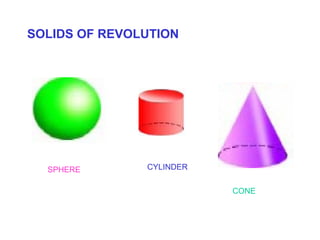
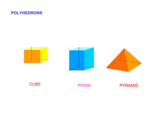
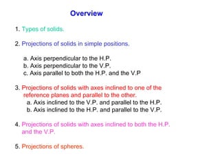
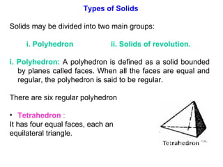
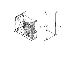
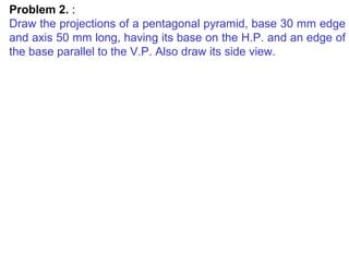
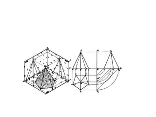
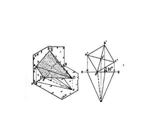
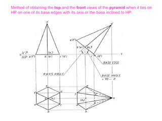
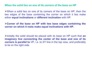
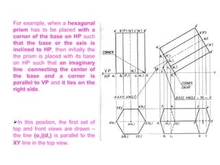
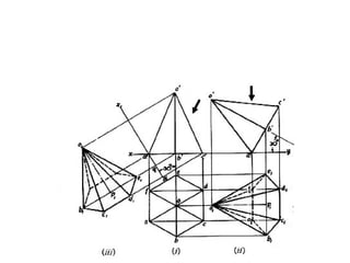
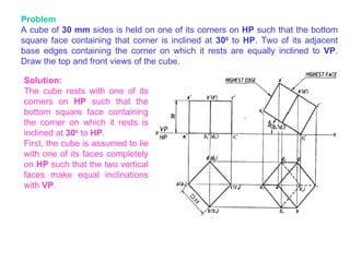
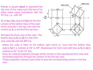
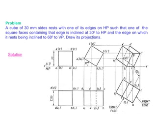
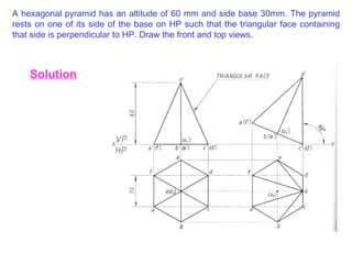
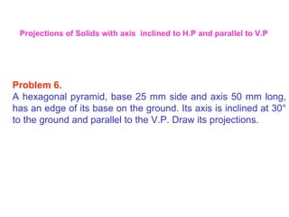
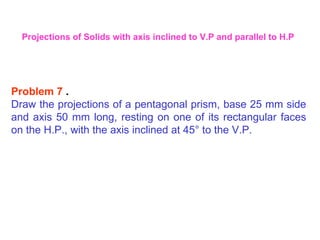
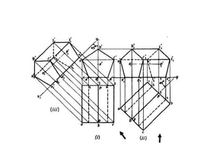
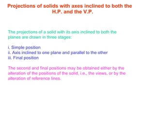
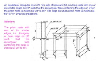
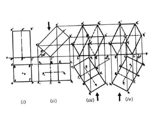
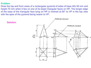
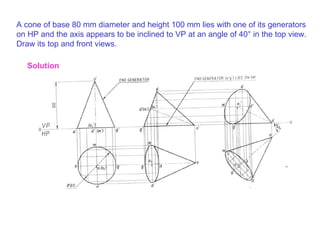
The document discusses the projection of solids and provides examples of how to project solids in different positions. It describes how to project solids when the axis is perpendicular to or parallel to the horizontal and vertical planes. It also explains how to project solids when the axis is inclined to one of the planes. Examples are provided for projecting prisms, pyramids, cylinders and cones in various positions.
introduction of engineering graphics ,projection of points,lines,planes,solids,section of solids,development of surfaces,isometric projection,perspective projection
Scales
THIS SLIDE CONTAINS WHOLE SYLLABUS OF ENGINEERING DRAWING/GRAPHICS. IT IS THE MOST SIMPLE AND INTERACTIVE WAY TO LEARN ENGINEERING DRAWING.SYLLABUS IS RELATED TO rajiv gandhi proudyogiki vishwavidyalaya / rajiv gandhi TECHNICAL UNIVERSITY ,BHOPAL.
introduction of engineering graphics ,projection of points,lines,planes,solids,section of solids,development of surfaces,isometric projection,perspective projection
Download the original presentation for animation and clear understanding. This Presentation describes the concepts of Engineering Drawing of VTU Syllabus. However same can also be used for learning drawing concepts. Please write to me for suggestions and criticisms here: hareeshang@gmail.com or visit this website for more details: www.hareeshang.wikifoundry.com.
Section of solids, Computer Aided Machine Drawing (CAMD) of VTU Syllabus prepared by Hareesha N Gowda, Asst. Prof, Dayananda Sagar College of Engg, Blore. Please write to hareeshang@gmail.com for suggestions and criticisms.
Section of solids - ENGINEERING DRAWING/GRAPHICSAbhishek Kandare
Section of solids
THIS SLIDE CONTAINS WHOLE SYLLABUS OF ENGINEERING DRAWING/GRAPHICS. IT IS THE MOST SIMPLE AND INTERACTIVE WAY TO LEARN ENGINEERING DRAWING.SYLLABUS IS RELATED TO rajiv gandhi proudyogiki vishwavidyalaya / rajiv gandhi TECHNICAL UNIVERSITY ,BHOPAL.
introduction of engineering graphics ,projection of points,lines,planes,solids,section of solids,development of surfaces,isometric projection,perspective projection
Download the original presentation for animation and clear understanding. This Presentation describes the concepts of Engineering Drawing of VTU Syllabus. However same can also be used for learning drawing concepts. Please write to me for suggestions and criticisms here: hareeshang@gmail.com or visit this website for more details: www.hareeshang.wikifoundry.com.
Mechanical Drafting Projection of solidsGaurav Mistry
Introduction and types of solids, Terms of solids and projections, Basics of projections, projection of solids to different planes, projection when different element of solids are resting on HP or VP, Different stages of projections.
Projection of solids - ENGINEERING DRAWING/GRAPHICSAbhishek Kandare
Projection of solids
HIS SLIDE CONTAINS WHOLE SYLLABUS OF ENGINEERING DRAWING/GRAPHICS. IT IS THE MOST SIMPLE AND INTERACTIVE WAY TO LEARN ENGINEERING DRAWING.SYLLABUS IS RELATED TO rajiv gandhi proudyogiki vishwavidyalaya / rajiv gandhi TECHNICAL UNIVERSITY ,BHOPAL.
Types of Planes,Projection of Plane parallel to one plane and perpendicular to other plane, Projection of Plane inclined to one plane and perpendicular to other plane,orthographic projections of planes, first angle projection
Theory of Metal cutting - Principles of Metal cutting, orthogonal and oblique cutting, Merchant circle diagram, cutting forces, power requirements, Economics of machining,problems
Transcript: Selling digital books in 2024: Insights from industry leaders - T...BookNet Canada
The publishing industry has been selling digital audiobooks and ebooks for over a decade and has found its groove. What’s changed? What has stayed the same? Where do we go from here? Join a group of leading sales peers from across the industry for a conversation about the lessons learned since the popularization of digital books, best practices, digital book supply chain management, and more.
Link to video recording: https://bnctechforum.ca/sessions/selling-digital-books-in-2024-insights-from-industry-leaders/
Presented by BookNet Canada on May 28, 2024, with support from the Department of Canadian Heritage.
Accelerate your Kubernetes clusters with Varnish CachingThijs Feryn
A presentation about the usage and availability of Varnish on Kubernetes. This talk explores the capabilities of Varnish caching and shows how to use the Varnish Helm chart to deploy it to Kubernetes.
This presentation was delivered at K8SUG Singapore. See https://feryn.eu/presentations/accelerate-your-kubernetes-clusters-with-varnish-caching-k8sug-singapore-28-2024 for more details.
LF Energy Webinar: Electrical Grid Modelling and Simulation Through PowSyBl -...DanBrown980551
Do you want to learn how to model and simulate an electrical network from scratch in under an hour?
Then welcome to this PowSyBl workshop, hosted by Rte, the French Transmission System Operator (TSO)!
During the webinar, you will discover the PowSyBl ecosystem as well as handle and study an electrical network through an interactive Python notebook.
PowSyBl is an open source project hosted by LF Energy, which offers a comprehensive set of features for electrical grid modelling and simulation. Among other advanced features, PowSyBl provides:
- A fully editable and extendable library for grid component modelling;
- Visualization tools to display your network;
- Grid simulation tools, such as power flows, security analyses (with or without remedial actions) and sensitivity analyses;
The framework is mostly written in Java, with a Python binding so that Python developers can access PowSyBl functionalities as well.
What you will learn during the webinar:
- For beginners: discover PowSyBl's functionalities through a quick general presentation and the notebook, without needing any expert coding skills;
- For advanced developers: master the skills to efficiently apply PowSyBl functionalities to your real-world scenarios.
UiPath Test Automation using UiPath Test Suite series, part 4DianaGray10
Welcome to UiPath Test Automation using UiPath Test Suite series part 4. In this session, we will cover Test Manager overview along with SAP heatmap.
The UiPath Test Manager overview with SAP heatmap webinar offers a concise yet comprehensive exploration of the role of a Test Manager within SAP environments, coupled with the utilization of heatmaps for effective testing strategies.
Participants will gain insights into the responsibilities, challenges, and best practices associated with test management in SAP projects. Additionally, the webinar delves into the significance of heatmaps as a visual aid for identifying testing priorities, areas of risk, and resource allocation within SAP landscapes. Through this session, attendees can expect to enhance their understanding of test management principles while learning practical approaches to optimize testing processes in SAP environments using heatmap visualization techniques
What will you get from this session?
1. Insights into SAP testing best practices
2. Heatmap utilization for testing
3. Optimization of testing processes
4. Demo
Topics covered:
Execution from the test manager
Orchestrator execution result
Defect reporting
SAP heatmap example with demo
Speaker:
Deepak Rai, Automation Practice Lead, Boundaryless Group and UiPath MVP
Let's dive deeper into the world of ODC! Ricardo Alves (OutSystems) will join us to tell all about the new Data Fabric. After that, Sezen de Bruijn (OutSystems) will get into the details on how to best design a sturdy architecture within ODC.
GDG Cloud Southlake #33: Boule & Rebala: Effective AppSec in SDLC using Deplo...James Anderson
Effective Application Security in Software Delivery lifecycle using Deployment Firewall and DBOM
The modern software delivery process (or the CI/CD process) includes many tools, distributed teams, open-source code, and cloud platforms. Constant focus on speed to release software to market, along with the traditional slow and manual security checks has caused gaps in continuous security as an important piece in the software supply chain. Today organizations feel more susceptible to external and internal cyber threats due to the vast attack surface in their applications supply chain and the lack of end-to-end governance and risk management.
The software team must secure its software delivery process to avoid vulnerability and security breaches. This needs to be achieved with existing tool chains and without extensive rework of the delivery processes. This talk will present strategies and techniques for providing visibility into the true risk of the existing vulnerabilities, preventing the introduction of security issues in the software, resolving vulnerabilities in production environments quickly, and capturing the deployment bill of materials (DBOM).
Speakers:
Bob Boule
Robert Boule is a technology enthusiast with PASSION for technology and making things work along with a knack for helping others understand how things work. He comes with around 20 years of solution engineering experience in application security, software continuous delivery, and SaaS platforms. He is known for his dynamic presentations in CI/CD and application security integrated in software delivery lifecycle.
Gopinath Rebala
Gopinath Rebala is the CTO of OpsMx, where he has overall responsibility for the machine learning and data processing architectures for Secure Software Delivery. Gopi also has a strong connection with our customers, leading design and architecture for strategic implementations. Gopi is a frequent speaker and well-known leader in continuous delivery and integrating security into software delivery.
"Impact of front-end architecture on development cost", Viktor TurskyiFwdays
I have heard many times that architecture is not important for the front-end. Also, many times I have seen how developers implement features on the front-end just following the standard rules for a framework and think that this is enough to successfully launch the project, and then the project fails. How to prevent this and what approach to choose? I have launched dozens of complex projects and during the talk we will analyze which approaches have worked for me and which have not.
DevOps and Testing slides at DASA ConnectKari Kakkonen
My and Rik Marselis slides at 30.5.2024 DASA Connect conference. We discuss about what is testing, then what is agile testing and finally what is Testing in DevOps. Finally we had lovely workshop with the participants trying to find out different ways to think about quality and testing in different parts of the DevOps infinity loop.
Software Delivery At the Speed of AI: Inflectra Invests In AI-Powered QualityInflectra
In this insightful webinar, Inflectra explores how artificial intelligence (AI) is transforming software development and testing. Discover how AI-powered tools are revolutionizing every stage of the software development lifecycle (SDLC), from design and prototyping to testing, deployment, and monitoring.
Learn about:
• The Future of Testing: How AI is shifting testing towards verification, analysis, and higher-level skills, while reducing repetitive tasks.
• Test Automation: How AI-powered test case generation, optimization, and self-healing tests are making testing more efficient and effective.
• Visual Testing: Explore the emerging capabilities of AI in visual testing and how it's set to revolutionize UI verification.
• Inflectra's AI Solutions: See demonstrations of Inflectra's cutting-edge AI tools like the ChatGPT plugin and Azure Open AI platform, designed to streamline your testing process.
Whether you're a developer, tester, or QA professional, this webinar will give you valuable insights into how AI is shaping the future of software delivery.
Neuro-symbolic is not enough, we need neuro-*semantic*Frank van Harmelen
Neuro-symbolic (NeSy) AI is on the rise. However, simply machine learning on just any symbolic structure is not sufficient to really harvest the gains of NeSy. These will only be gained when the symbolic structures have an actual semantics. I give an operational definition of semantics as “predictable inference”.
All of this illustrated with link prediction over knowledge graphs, but the argument is general.
2. INTRODUCTION A solid has three dimensions, viz. length, breadth and thickness. To represent a solid on a flat surface having only length and breadth, at least two orthographic views are necessary.
5. Overview 1. Types of solids. 2. Projections of solids in simple positions. a. Axis perpendicular to the H.P. b. Axis perpendicular to the V.P. c. Axis parallel to both the H.P. and the V.P 3. Projections of solids with axes inclined to one of the reference planes and parallel to the other. a. Axis inclined to the V.P. and parallel to the H.P. b. Axis inclined to the H.P. and parallel to the V.P. 4. Projections of solids with axes inclined to both the H.P. and the V.P. 5. Projections of spheres.
6.
7. b. Cube or Hexahedron : It has six faces, all equal squares. c. Octahedron : It has eight equal equilateral triangles as faces. d. Dodecahedron : It has twelve equal and regular pentagons as faces.
8. Prism : This is a polyhedron having two equal and similar faces called its ends or bases, parallel to each other and joined by other faces, which are parallelograms. The imaginary line joining the centers of the bases is called the axis. A right and regular prism has its axis perpendicular to the bases. All its faces are equal rectangles.
9. Pyramid: This is a polyhedron having a plane figure as a base and a number of triangular faces meeting at a point called the vertex or apex. The imaginary line joining the apex with the centre of the base is its axis. A right and regular pyramid has its axis perpendicular to the base, which is a regular plane figure. Its faces are all equal isosceles triangles.
10. Solids of Revolution Definition: Solids which are generated by rotating a plane surface about one of its sides Three Types Cylinder Cone Sphere
11. a) Cylinder A right circular cylinder is a solid generated by the revolution of a rectangle about one of its sides, which remains fixed. It has two equal circular bases. The line joining the centers of the bases is the axis. It is perpendicular to the bases.
12. b. Cone : A right circular cone is a solid generated by the revolution of right-angled triangles about one of its perpendicular sides, which is fixed.
13. It has one circular base. Its axis joins the apex with the centre of the base to which it is perpendicular. Straight lines drawn from the apex to the circumference of the base-circle are all equal and are called generators of the cone.
14. c. Sphere : A sphere is a solid generated by the revolution of a semi-circle about its diameter as the axis. The mid-point of the diameter is the centre of the sphere. All points on the surface of the sphere are equidistant from its centre.
15. d. Frustum: When a pyramid or a cone is cut by a plane parallel to its base, thus removing the top portion, the remaining portion is called its frustum. e. Truncated: When a solid is cut by a plane inclined to base it is said to be truncated. Unless and otherwise stated, the given solid should be understood as right and regular .
16.
17. Therefore, the projection of a solid on the plane to which its axis is perpendicular will show the true shape and size of its base. Hence, when the axis is perpendicular to the ground, i.e. to the H.P., the top view should be drawn first and the front view projected from it. When the axis is perpendicular to the V.P., beginning should be made with the front view. The top view should then be projected from it. When the axis is parallel to both the H.P. and the V.P., neither the top view nor the front view will show the actual shape of the base. In this case, the projection of the solid on an auxiliary plane perpendicular to both the planes, viz. the side view must be both the planes, viz. the side view must be drawn first. The front view and the top view are then projected from the side view. The projections in such cases may also be drawn in two stages.
18.
19.
20. Problem 2. : Draw the projections of a pentagonal pyramid, base 30 mm edge and axis 50 mm long, having its base on the H.P. and an edge of the base parallel to the V.P. Also draw its side view.
21.
22. Problem 3. Draw the projections of (i) a cylinder, base 40 mm diameter and axis 50 mm long, and (ii) a cone, base 40 mm diameter and axis 50 mm long, resting on the H.P. on their respective bases.
23.
24. Problem 4. A cube of 50 mm long edges is resting on the H.P. with its vertical faces equally inclined to the V.P. Draw its projections.
25.
26. Problem 5. A square pyramid, base 40 mm side and axis 65 mm long, has its base in the V.P. One edge of the base is inclined at 30 degrees to the H.P. and a corner contained by that edge is on the H.P. Draw its projections .
27.
28. When a solid is placed on the HP with axis inclined to horizontal plane of projection , the elemental portion of the solid that lies on H.P depends upon the type of solid. When a prism is placed on H.P with its axis inclined to it, then it will lie either on one of its base edges or one of its corners on H.P When a pyramid is placed on H.P with its axis inclined to H.P then we will have one of its base edges on H.P (or) one of its base corners on H.P (or) one of its slant edges on H.P (or) one of its triangular faces on H.P (or) an apex on H.P . PRISM PYRAMID Projections of Solids with axes inclined to one of the reference planes and parallel to the other plane
29. When a solid lies with an edge of the base on the H.P If the solid is required to be placed with an edge of the base on the H.P then initially the solid has to be placed with its base on H.P such that an edge of the base is perpendicular to V.P i.e to XY line in the top view preferably on the right side. When a pentagonal prism has to be placed with an edge of base on H.P such that the base or axis is inclined to H.P then initially the prism is placed with its base on H.P with an edge of its base perpendicular to V.P and lying to the right side. In this position the first set of top views and front views are drawn with the base edges (c 1 )(d 1 ) perpendicular to XY line in the top view. In the front view this edge c 1 ’(d 1 ’ ) appears as a point.
30. Since the prism has to lie with an edge of the base on the H.P the front view of the prism is tilted on the edge c 1 ’(d 1 ’) such that the axis is inclined at θ to H.P. Redraw the first front view in the tilted position. Whenever the inclination of axis θ with H.P is given first the base is drawn at (90- θ ) in the front view, otherwise improper selection of the position of the axis may result in the base edge c 1 ’(d 1 ’) lying above or below the XY line. The second top view is projected by drawing the vertical projectors from the corners of the second front view and the horizontal projectors from the first top view.
31. Method of obtaining the top and the front views of the pyramid when it lies on HP on one of its base edges with its axis or the base inclined to HP.
32.
33.
34. Methods for obtaining top and front views of the pyramid when it rests on HP on one of its base corners such that the two base edges containing the corner on which it rests make equal inclinations with HP.
35. When a pyramid lies on one of its triangular faces on HP If a pyramid has to be placed on one of its triangular faces on HP, then initially let the pyramid be placed with its base on HP. In the first front view, the right side inclined line, i.e., o’c’(d’) represents a triangular face. Redraw the front view such that the triangular face o’c’(d’) lies on HP.
36. When a pyramid lies on one of its slant edges on HP When a pyramid lies with one of its slant edges on HP, then two triangular faces containing the slant edge on which it rests make either equal inclinations or different inclinations with HP.
37. Projections of solids with axes inclined to one of the reference planes and parallel to the other When a solid has its axis inclined to one plane and parallel to the other, it projections are drawn in two stages. a. In the initial stage, the solid is assumed to be in simple position, i.e. its axis perpendicular to one of the planes. If the axis is to be inclined to the ground, i.e. the H.P., it is assumed to be perpendicular to the H.P. in the initial stage. Similarly, if the axis is to be inclined to the V.P., it is kept perpendicular to the V.P. in the initial stage. Moreover i. If the solid has an edge of its base parallel to the H.P. or in the H.P. or on the ground, that edge should be kept perpendicular to the V.P.; if the edge of the base is parallel to the V.P. or in the V.P., it should be kept perpendicular to the H.P. ii. If the solid has a corner of its base in the H.P. or on the ground, the sides of the base containing that corner should be kept equally inclined to the V.P.; if the corner is in the V.P., they should be kept equally inclined to the H.P.
38. Methods of drawing the projections of solids Two methods Change of position method – The solids are placed first in the simple position and then tilted successively in two or three stages to obtain the final position. Auxiliary plane method (Change of reference-line method) – The solids are placed initially in the simple position and then one or two auxiliary planes are setup to obtain the views in the required position.
39.
40. Problem A cube of 30 mm sides is held on one of its corners on HP such that the bottom square face containing that corner is inclined at 30 0 to HP . Two of its adjacent base edges containing the corner on which it rests are equally inclined to VP . Draw the top and front views of the cube. Solution: The cube rests with one of its corners on HP such that the bottom square face containing the corner on which it rests is inclined at 30 0 to HP . First, the cube is assumed to lie with one of its faces completely on HP such that the two vertical faces make equal inclinations with VP .
41.
42. Problem A cube of 30 mm sides rests with one of its edges on HP such that one of the square faces containing that edge is inclined at 30 0 to HP and the edge on which it rests being inclined to 60 0 to VP. Draw its projections. Solution
43. A hexagonal pyramid has an altitude of 60 mm and side base 30mm. The pyramid rests on one of its side of the base on HP such that the triangular face containing that side is perpendicular to HP. Draw the front and top views. Solution
44. Projections of solids with axes inclined to one of the reference planes and parallel to the other When a solid has its axis inclined to one plane and parallel to the other, it projections are drawn in two stages. a. In the initial stage, the solid is assumed to be in simple position, i.e. its axis perpendicular to one of the planes. If the axis is to be inclined to the ground, i.e. the H.P., it is assumed to be perpendicular to the H.P. in the initial stage. Similarly, if the axis is to be inclined to the V.P., it is kept perpendicular to the V.P. in the initial stage. Moreover i. If the solid has an edge of its base parallel to the H.P. or in the H.P. or on the ground, that edge should be kept perpendicular to the V.P.; if the edge of the base is parallel to the V.P. or in the V.P., it should be kept perpendicular to the H.P. ii. If the solid has a corner of its base in the H.P. or on the ground, the sides of the base containing that corner should be kept equally inclined to the V.P.; if the corner is in the V.P., they should be kept equally inclined to the H.P.
45. Problem 6. A hexagonal pyramid, base 25 mm side and axis 50 mm long, has an edge of its base on the ground. Its axis is inclined at 30 ° to the ground and parallel to the V.P. Draw its projections. Projections of Solids with axis inclined to H.P and parallel to V.P
46.
47. Problem 7 . Draw the projections of a pentagonal prism, base 25 mm side and axis 50 mm long, resting on one of its rectangular faces on the H.P., with the axis inclined at 45 ° to the V.P. Projections of Solids with axis inclined to V.P and parallel to H.P
48.
49. Problem 8 Draw the projections of a cylinder 75 mm diameter and 100 mm long, lying on the ground with its axis inclined at 30 ° to the V.P. and parallel to the ground.
50.
51. Projections of solids with axes inclined to both the H.P. and the V.P. The projections of a solid with its axis inclined to both the planes are drawn in three stages: i. Simple position ii. Axis inclined to one plane and parallel to the other iii. Final position The second and final positions may be obtained either by the alteration of the positions of the solid, i.e., the views, or by the alteration of reference lines.
52. An equilateral triangular prism 20 mm side of base and 50 mm long rests with one of its shorter edges on HP such that the rectangular face containing the edge on which the prism rests is inclined at 30 ° to HP. The edge on which prism rests is inclined at 60 ° to VP. Draw its projections . Solution: The prism rests with one of its shorter edges, i.e., triangular or base edge on HP such that the rectangular face containing that edge is inclined at 30 ° to HP.
53. Problem 9 A square prism, base 40 mm side and height 65 mm, has its axis inclined at 45 degrees to the H.P. and has an edge of its base, on the H.P. and inclined at 30 degrees to the V.P. Draw its projections.
54.
55. Problem Draw the top and front views of a rectangular pyramid of sides of base 40x 50 mm and height 70 mm when it lies on one of its larger triangular faces on HP. The longer edge of the base of the triangular face lying on HP is inclined at 60 ° to VP in the top view with the apex of the pyramid being nearer to VP. Solution
56. A cone of base 80 mm diameter and height 100 mm lies with one of its generators on HP and the axis appears to be inclined to VP at an angle of 40 ° in the top view. Draw its top and front views. Solution
57. Draw the top and the front views of a right circular cylinder of base 45 mm diameter and 60 mm long when it lies on HP such that its axis is inclined at 35 ° to HP and the axis appears to be perpendicular to VP in the top view. Solution