Download to read offline
![By: Inst. Dawit W.
ASSOSA UNIVERSITY, DEPARTMENT OFMECHANICAL ENGINEERING [ Assosa,Ethiopia]
AUXILIARY VIEW](https://image.slidesharecdn.com/auxiliaryviews-210527122628/85/Auxiliary-views-1-320.jpg)
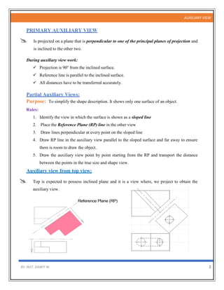
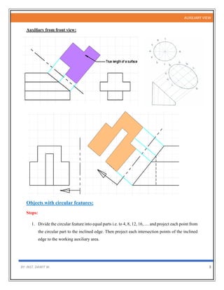
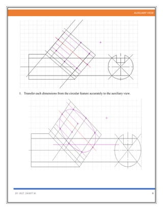

1. Auxiliary views are used to illustrate the true size and shape of inclined surfaces that cannot be shown in standard top, front, and side views. 2. There are two types of auxiliary views: primary auxiliary views which are perpendicular to one principal plane and inclined to the other two, and secondary auxiliary views which are projected from a primary auxiliary view. 3. Auxiliary views serve to show the true size of a surface, true shape including all true angles, and are used to project and complete other views.


![8. Auxilary Projections with example [Repaired].pptx](https://cdn.slidesharecdn.com/ss_thumbnails/8-240304062220-18bbd917-thumbnail.jpg?width=640&height=640&fit=bounds)


