Here are the key steps to sketching an object:
1. Look at the object from different angles to understand its overall shape and details.
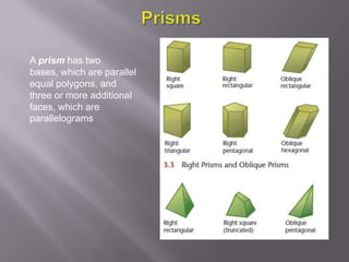
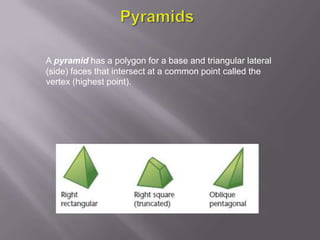
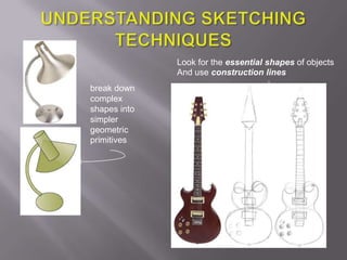
2. Break down the object into simple geometric shapes like cubes, spheres, cones, cylinders etc. These are called primitives.
3. Use construction lines to lay out the positions and proportions of the primitives. Construction lines help ensure accuracy and proper perspective.
4. Sketch the outlines of each primitive using construction lines as guides. Keep lines light so they can be erased.
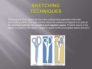
5. Add details like holes, edges, surface textures once the overall form is established.
6. Erase construction lines and clean up lines using precise, dark strokes