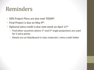
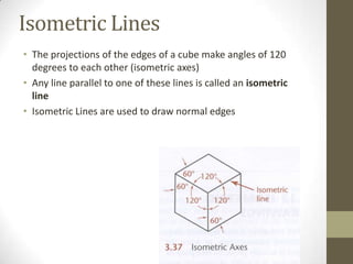
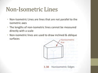
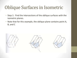
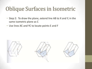
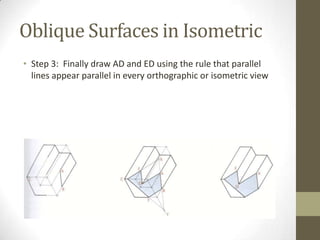
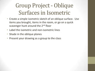
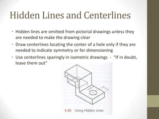
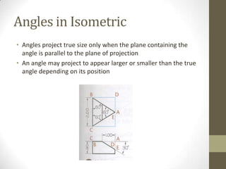
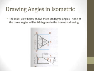
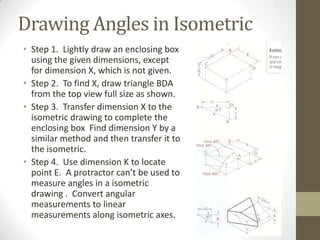
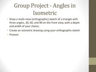
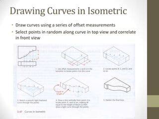
2D Essentials


Instructor: Laura Gerold, PE
Catalog #10614113
Class # 22784, 24113, 24136, & 24138
Class Start: January 18, 2012
Class End: May 16, 2012
Reminders
• 50% Project Plans are due next TODAY!
• Final Project is due on May 9th.
• Optional extra credit is due next week on April 11th
  • Find other countries where 1st and 3rd angle projections are used
    for 5 extra points
  • Details are on blackboard in class materials / extra credit folder
Chapter 3 – Isometric
      Drawing
Group Project
• Individually Create an object using your blocks.
• Draw an isometric drawing of your creations.
• Trade your drawing with someone in a different row.
• With a new drawing in hand from someone else, create the
  object on the plan using your blocks.
• Questions
    • Can you create the object with an isometric drawing only?
    • Was it easier or harder than creating an object using the
      orthographic plans?
    • Which method would you prefer, or would you like both for
      creating a part in the “real-world?”
Axonometric Drawings
• Axonometric projection is a type of
  parallel projection, more specifically a
  type of orthographic projection, used to
  create a pictorial drawing of an object,
  where the object is rotated along one or
  more of its axes relative to the plane of
  projection.
• Different from orthographic because of
  the angle the object is “tipped”
• "Axonometric" means "to measure
  along axes". There are three axes.
• There are three main types of
  axonometric projection: isometric,
  dimetric, and trimetric projection.
Axonometric Drawings
• Foreshortening – reducing the length of a line to create an
  illusion of an object being in 3D
• Isometric Projection – equal foreshortening along each of the
  three axis
• Isometric is the most common form of axonometric projection
  used.
Axonometric Drawings
 • Dimetric Projection – equal foreshortening along two axis, and
   a different along the third axis. Not “tipped” evenly on all
   planes of projection.


Source: http://draftingmanuals.tpub.com/14276/css/14276_326.htm
Axonometric Drawings
• Trimetric projection – different foreshortening along all three
  axis directions


 Source: http://draftingmanuals.tpub.com/14276/css/14276_327.htm
Isometric Lines
• The projections of the edges of a cube make angles of 120
  degrees to each other (isometric axes)
• Any line parallel to one of these lines is called an isometric
  line
• Isometric Lines are used to draw normal edges
Non-Isometric Lines
• Non-Isometric Lines are lines that are not parallel to the
  isometric axes
• The lengths of non-isometric lines cannot be measured
  directly with a scale
• Non-isometric lines are used to draw inclined & oblique
  surfaces
Oblique Surfaces in Isometric
• Step 1: Find the intersections of the oblique surfaces with the
  isometric planes.
• Note that for this example, the oblique plane contains point A,
  B, and C
Oblique Surfaces in Isometric
• Step 2: To draw the plane, extend line AB to X and Y, in the
  same isometric plane as C
• Use lines XC and YC to locate points E and F
Oblique Surfaces in Isometric
• Step 3: Finally draw AD and ED using the rule that parallel
  lines appear parallel in every orthographic or isometric view
Group Project - Oblique
        Surfaces in Isometric
• Create a simple isometric sketch of an oblique surface. Use
  items you brought, items in the room, or go on a quick
  scavenger hunt around the 2nd floor
• Label the isometric and non-isometric lines
• Shade in the oblique planes
• Present your drawing as a group to the class
Hidden Lines and Centerlines
• Hidden lines are omitted from pictorial drawings unless they
  are needed to make the drawing clear
• Draw centerlines locating the center of a hole only if they are
  needed to indicate symmetry or for dimensioning
• Use centerlines sparingly in isometric drawings - “If in doubt,
  leave them out”
Angles in Isometric
• Angles project true size only when the plane containing the
  angle is parallel to the plane of projection
• An angle may project to appear larger or smaller than the true
  angle depending on its position
Drawing Angles in Isometric
• The multi-view below shows three 60 degree angles. None of
  the three angles will be 60 degrees in the isometric drawing.
Drawing Angles in Isometric
• Step 1. Lightly draw an enclosing box
  using the given dimensions, except
  for dimension X, which is not given.
• Step 2. To find X, draw triangle BDA
  from the top view full size as shown.
• Step 3. Transfer dimension X to the
  isometric drawing to complete the
  enclosing box Find dimension Y by a
  similar method and then transfer it to
  the isometric.
• Step 4. Use dimension K to locate
  point E. A protractor can’t be used to
  measure angles in a isometric
  drawing . Convert angular
  measurements to linear
  measurements along isometric axes.
Group Project - Angles in
            Isometric
• Draw a multi-view (orthographic) sketch of a triangle with
  three angles, 30, 60, and 90 on the front view, with a depth
  and width of your choice.
• Create an isometric drawing using your orthographic sketch
• Present
Drawing Curves in Isometric
• Draw curves using a series of offset measurements
• Select points in random along curve in top view and correlate
  in front view
Drawing Holes in Isometric
• When a circle lies in a plane that is not parallel to the plane of
  projection, the circle projects as an ellipse.
• The ellipse can be constructed using offset measurements.
• There are several different methods that can be used to draw
  an isometric ellipse . . . We’ll cover a couple in class.
Isometric Ellipse – Random
         Line Method
• Step 1: Draw parallel lines
  spaced at random across
  the circle
• Step 2: Transfer these lines
  to the isometric drawing
Isometric Ellipse in a non-
        isometric plane
• If the curve lies on a non-isometric plane (it is inclined or
  oblique), can not directly apply offset measurements
• Step 1. Draw lines in the orthographic view to locate points
Isometric Ellipse in a non-
        isometric plane
• Step 2 Enclose the cylinder in a construction box and draw
  the box in the isometric drawing
• Draw the base using offset measurements
• Construct the inclined ellipse by locating points and drawing
  the final curve through them
Isometric Ellipse in a non-
        isometric plane
• Step 3: Darken the final lines
Orienting Ellipses in Isometric
• All diagonals on an isometric cube are horizontal or are at 60
  degrees to the horizontal
• Approximate ellipses drawn using the four center method are
  accurate enough for most isometric drawings
Drawing a 4-Center Ellipse
• Step 1. Draw or
  imagine a square
  enclosing the circle in
  the multi-view
  drawing
• Draw the isometric
  view of the square
  (with sides equal to
  the diameter of the
  circle).
Drawing a 4-Center Ellipse
• Step 2. Mark the
  midpoint of each line
• Step 3. Draw two
  large arcs with radius
  R, from the
  intersections of the
  perpendiculars in the
  closest corners
• Step 4. Draw the two
  small arcs with radius,
  r
• Demonstration
Group Project - Isometric
             Ellipses
• Use your blocks to build a simple object
• Draw the object in isometric complete with holes show as
  isometric ellipse
• If you brought an item with holes , you can draw that item
  instead
• Present drawings
Isometric Cylinders
• To create an isometric cylinder, connect two ellipses with
  parallel lines tangent to the appropriate axis
Group Project – Isometric
            Cylinders
• Use an object you brought, that I have, or that you find in a
  room and draw an isometric cylinder
• Present results
Screw Threads in Isometric
• Use parallel partial ellipses equally spaced at the symbolic
  thread pitch to represent the crests of a screw thread in
  isometric
Visualization Exercise
• http://www.wisc-
  online.com/objects/ViewObject.aspx?ID=ENG20004
Chapter 7 – Section
      Views
Why do we need Section
             Views?
• To see what is “hidden” within a item to be able to build it
• To show the material that the item is built out of
• How-To Architect
UNDERSTANDING SECTIONS
Section views are used for three main purposes:
• To document the design and manufacture of single parts that are manufactured as one
  piece.
• To document how multiple parts are to be assembled or built.
• To aid in visualizing the internal workings of a design.


                                                                 When the part is cut fully
                                                                 in half, the resulting view
                                                                 is called a full section.
The Cutting Plane
The cutting plane appears edgewise as a thick
dashed line called the cutting-plane line. The arrows
at the ends of the cutting-plane line indicate the
direction of sight for the sectional view.


              The Cutting Plane
Visible Edges on Cutting Planes


Newly visible edges cut by cutting plane are
crosshatched with section lining.
LABELING CUTTING PLANES


          Note that each section (A-A and B-B)
          is completely independent.
RULES FOR LINES IN SECTION
          VIEWS

  • Show edges and
   contours that are
 now visible behind the
    cutting plane.

 • Omit hidden lines in
    section views.
RULES FOR LINES IN SECTION
              VIEWS
• Show edges and contours
that are now visible behind the
cutting plane.

• Omit hidden lines in section
views.

• A sectioned area is always
completely bounded by a
visible outline—never by a
hidden line.

• A visible line can never
cross a sectioned area in a
view of a single part.
CUTTING-PLANE LINE STYLE
It is made up of equal dashes, each about 6 mm (1/4“) long ending in arrowheads. This form
works especially well for drawings. The alternative style, uses alternating long dashes and pairs
of short dashes and ends with arrowheads. This style has been in general use for a long time, so
you may still see it on drawings. Both lines are drawn the same thickness as visible lines. The
arrowheads at the ends of the cutting plane line indicate the direction in which the cutaway object
is viewed.


  Alternative Methods for
  Showing a Cutting Plane
  A and B.
Visualizing Cutting-Plane
        Direction


  Correct and Incorrect Cutting-Plane Line Placement
SECTION-LINING TECHNIQUE
• Uniformly spaced by an interval of about 2.5 mm
• Not too close together
• Uniformly thin, not varying in thickness
• Distinctly thinner than visible lines
• Neither running beyond nor stopping short of visible
  outlines
SECTION-LINING TECHNIQUE
       continued….
Group Project - Section Views
• Draw a section view of a simple object (blocks?) in the room
Section Views Visualization
           Exercise
• http://www.wisc-
  online.com/objects/ViewObject.aspx?ID=ENG19804
What’s Next?
• Finish Chapter 7 – Section Views
Questions?
• On one of your sketches, answer the following two questions:
  • What was the most useful thing that you learned today?
  • What do you still have questions about?
Homework
Chapter 3 Exercises: 3.1 (h, i – isometric sketch only)
Chapter 7 Review Questions: 1

Class 10 presentation

  • 1.
    2D Essentials Instructor: LauraGerold, PE Catalog #10614113 Class # 22784, 24113, 24136, & 24138 Class Start: January 18, 2012 Class End: May 16, 2012
  • 2.
    Reminders • 50% ProjectPlans are due next TODAY! • Final Project is due on May 9th. • Optional extra credit is due next week on April 11th • Find other countries where 1st and 3rd angle projections are used for 5 extra points • Details are on blackboard in class materials / extra credit folder
  • 3.
    Chapter 3 –Isometric Drawing
  • 4.
    Group Project • IndividuallyCreate an object using your blocks. • Draw an isometric drawing of your creations. • Trade your drawing with someone in a different row. • With a new drawing in hand from someone else, create the object on the plan using your blocks. • Questions • Can you create the object with an isometric drawing only? • Was it easier or harder than creating an object using the orthographic plans? • Which method would you prefer, or would you like both for creating a part in the “real-world?”
  • 5.
    Axonometric Drawings • Axonometricprojection is a type of parallel projection, more specifically a type of orthographic projection, used to create a pictorial drawing of an object, where the object is rotated along one or more of its axes relative to the plane of projection. • Different from orthographic because of the angle the object is “tipped” • "Axonometric" means "to measure along axes". There are three axes. • There are three main types of axonometric projection: isometric, dimetric, and trimetric projection.
  • 6.
    Axonometric Drawings • Foreshortening– reducing the length of a line to create an illusion of an object being in 3D • Isometric Projection – equal foreshortening along each of the three axis • Isometric is the most common form of axonometric projection used.
  • 7.
    Axonometric Drawings •Dimetric Projection – equal foreshortening along two axis, and a different along the third axis. Not “tipped” evenly on all planes of projection. Source: http://draftingmanuals.tpub.com/14276/css/14276_326.htm
  • 8.
    Axonometric Drawings • Trimetricprojection – different foreshortening along all three axis directions Source: http://draftingmanuals.tpub.com/14276/css/14276_327.htm
  • 9.
    Isometric Lines • Theprojections of the edges of a cube make angles of 120 degrees to each other (isometric axes) • Any line parallel to one of these lines is called an isometric line • Isometric Lines are used to draw normal edges
  • 10.
    Non-Isometric Lines • Non-IsometricLines are lines that are not parallel to the isometric axes • The lengths of non-isometric lines cannot be measured directly with a scale • Non-isometric lines are used to draw inclined & oblique surfaces
  • 11.
    Oblique Surfaces inIsometric • Step 1: Find the intersections of the oblique surfaces with the isometric planes. • Note that for this example, the oblique plane contains point A, B, and C
  • 12.
    Oblique Surfaces inIsometric • Step 2: To draw the plane, extend line AB to X and Y, in the same isometric plane as C • Use lines XC and YC to locate points E and F
  • 13.
    Oblique Surfaces inIsometric • Step 3: Finally draw AD and ED using the rule that parallel lines appear parallel in every orthographic or isometric view
  • 14.
    Group Project -Oblique Surfaces in Isometric • Create a simple isometric sketch of an oblique surface. Use items you brought, items in the room, or go on a quick scavenger hunt around the 2nd floor • Label the isometric and non-isometric lines • Shade in the oblique planes • Present your drawing as a group to the class
  • 15.
    Hidden Lines andCenterlines • Hidden lines are omitted from pictorial drawings unless they are needed to make the drawing clear • Draw centerlines locating the center of a hole only if they are needed to indicate symmetry or for dimensioning • Use centerlines sparingly in isometric drawings - “If in doubt, leave them out”
  • 16.
    Angles in Isometric •Angles project true size only when the plane containing the angle is parallel to the plane of projection • An angle may project to appear larger or smaller than the true angle depending on its position
  • 17.
    Drawing Angles inIsometric • The multi-view below shows three 60 degree angles. None of the three angles will be 60 degrees in the isometric drawing.
  • 18.
    Drawing Angles inIsometric • Step 1. Lightly draw an enclosing box using the given dimensions, except for dimension X, which is not given. • Step 2. To find X, draw triangle BDA from the top view full size as shown. • Step 3. Transfer dimension X to the isometric drawing to complete the enclosing box Find dimension Y by a similar method and then transfer it to the isometric. • Step 4. Use dimension K to locate point E. A protractor can’t be used to measure angles in a isometric drawing . Convert angular measurements to linear measurements along isometric axes.
  • 19.
    Group Project -Angles in Isometric • Draw a multi-view (orthographic) sketch of a triangle with three angles, 30, 60, and 90 on the front view, with a depth and width of your choice. • Create an isometric drawing using your orthographic sketch • Present
  • 20.
    Drawing Curves inIsometric • Draw curves using a series of offset measurements • Select points in random along curve in top view and correlate in front view
  • 21.
    Drawing Holes inIsometric • When a circle lies in a plane that is not parallel to the plane of projection, the circle projects as an ellipse. • The ellipse can be constructed using offset measurements. • There are several different methods that can be used to draw an isometric ellipse . . . We’ll cover a couple in class.
  • 22.
    Isometric Ellipse –Random Line Method • Step 1: Draw parallel lines spaced at random across the circle • Step 2: Transfer these lines to the isometric drawing
  • 23.
    Isometric Ellipse ina non- isometric plane • If the curve lies on a non-isometric plane (it is inclined or oblique), can not directly apply offset measurements • Step 1. Draw lines in the orthographic view to locate points
  • 24.
    Isometric Ellipse ina non- isometric plane • Step 2 Enclose the cylinder in a construction box and draw the box in the isometric drawing • Draw the base using offset measurements • Construct the inclined ellipse by locating points and drawing the final curve through them
  • 25.
    Isometric Ellipse ina non- isometric plane • Step 3: Darken the final lines
  • 26.
    Orienting Ellipses inIsometric • All diagonals on an isometric cube are horizontal or are at 60 degrees to the horizontal • Approximate ellipses drawn using the four center method are accurate enough for most isometric drawings
  • 27.
    Drawing a 4-CenterEllipse • Step 1. Draw or imagine a square enclosing the circle in the multi-view drawing • Draw the isometric view of the square (with sides equal to the diameter of the circle).
  • 28.
    Drawing a 4-CenterEllipse • Step 2. Mark the midpoint of each line • Step 3. Draw two large arcs with radius R, from the intersections of the perpendiculars in the closest corners • Step 4. Draw the two small arcs with radius, r • Demonstration
  • 29.
    Group Project -Isometric Ellipses • Use your blocks to build a simple object • Draw the object in isometric complete with holes show as isometric ellipse • If you brought an item with holes , you can draw that item instead • Present drawings
  • 30.
    Isometric Cylinders • Tocreate an isometric cylinder, connect two ellipses with parallel lines tangent to the appropriate axis
  • 31.
    Group Project –Isometric Cylinders • Use an object you brought, that I have, or that you find in a room and draw an isometric cylinder • Present results
  • 32.
    Screw Threads inIsometric • Use parallel partial ellipses equally spaced at the symbolic thread pitch to represent the crests of a screw thread in isometric
  • 33.
    Visualization Exercise • http://www.wisc- online.com/objects/ViewObject.aspx?ID=ENG20004
  • 34.
    Chapter 7 –Section Views
  • 35.
    Why do weneed Section Views? • To see what is “hidden” within a item to be able to build it • To show the material that the item is built out of • How-To Architect
  • 36.
    UNDERSTANDING SECTIONS Section viewsare used for three main purposes: • To document the design and manufacture of single parts that are manufactured as one piece. • To document how multiple parts are to be assembled or built. • To aid in visualizing the internal workings of a design. When the part is cut fully in half, the resulting view is called a full section.
  • 37.
    The Cutting Plane Thecutting plane appears edgewise as a thick dashed line called the cutting-plane line. The arrows at the ends of the cutting-plane line indicate the direction of sight for the sectional view. The Cutting Plane
  • 38.
    Visible Edges onCutting Planes Newly visible edges cut by cutting plane are crosshatched with section lining.
  • 39.
    LABELING CUTTING PLANES Note that each section (A-A and B-B) is completely independent.
  • 40.
    RULES FOR LINESIN SECTION VIEWS • Show edges and contours that are now visible behind the cutting plane. • Omit hidden lines in section views.
  • 41.
    RULES FOR LINESIN SECTION VIEWS • Show edges and contours that are now visible behind the cutting plane. • Omit hidden lines in section views. • A sectioned area is always completely bounded by a visible outline—never by a hidden line. • A visible line can never cross a sectioned area in a view of a single part.
  • 42.
    CUTTING-PLANE LINE STYLE Itis made up of equal dashes, each about 6 mm (1/4“) long ending in arrowheads. This form works especially well for drawings. The alternative style, uses alternating long dashes and pairs of short dashes and ends with arrowheads. This style has been in general use for a long time, so you may still see it on drawings. Both lines are drawn the same thickness as visible lines. The arrowheads at the ends of the cutting plane line indicate the direction in which the cutaway object is viewed. Alternative Methods for Showing a Cutting Plane A and B.
  • 43.
    Visualizing Cutting-Plane Direction Correct and Incorrect Cutting-Plane Line Placement
  • 44.
    SECTION-LINING TECHNIQUE • Uniformlyspaced by an interval of about 2.5 mm • Not too close together • Uniformly thin, not varying in thickness • Distinctly thinner than visible lines • Neither running beyond nor stopping short of visible outlines
  • 45.
  • 46.
    Group Project -Section Views • Draw a section view of a simple object (blocks?) in the room
  • 47.
    Section Views Visualization Exercise • http://www.wisc- online.com/objects/ViewObject.aspx?ID=ENG19804
  • 48.
    What’s Next? • FinishChapter 7 – Section Views
  • 49.
    Questions? • On oneof your sketches, answer the following two questions: • What was the most useful thing that you learned today? • What do you still have questions about?
  • 50.
    Homework Chapter 3 Exercises:3.1 (h, i – isometric sketch only) Chapter 7 Review Questions: 1