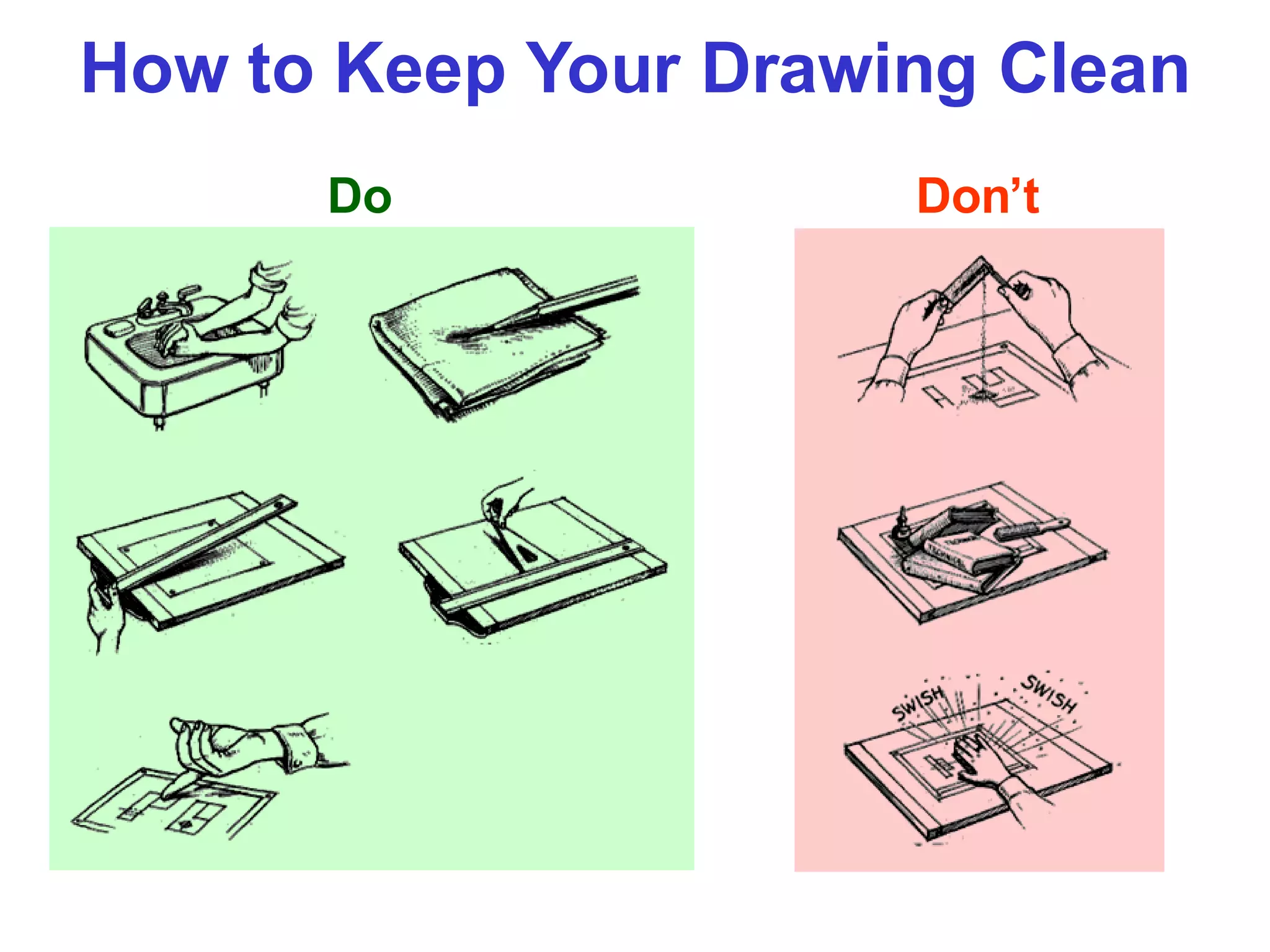
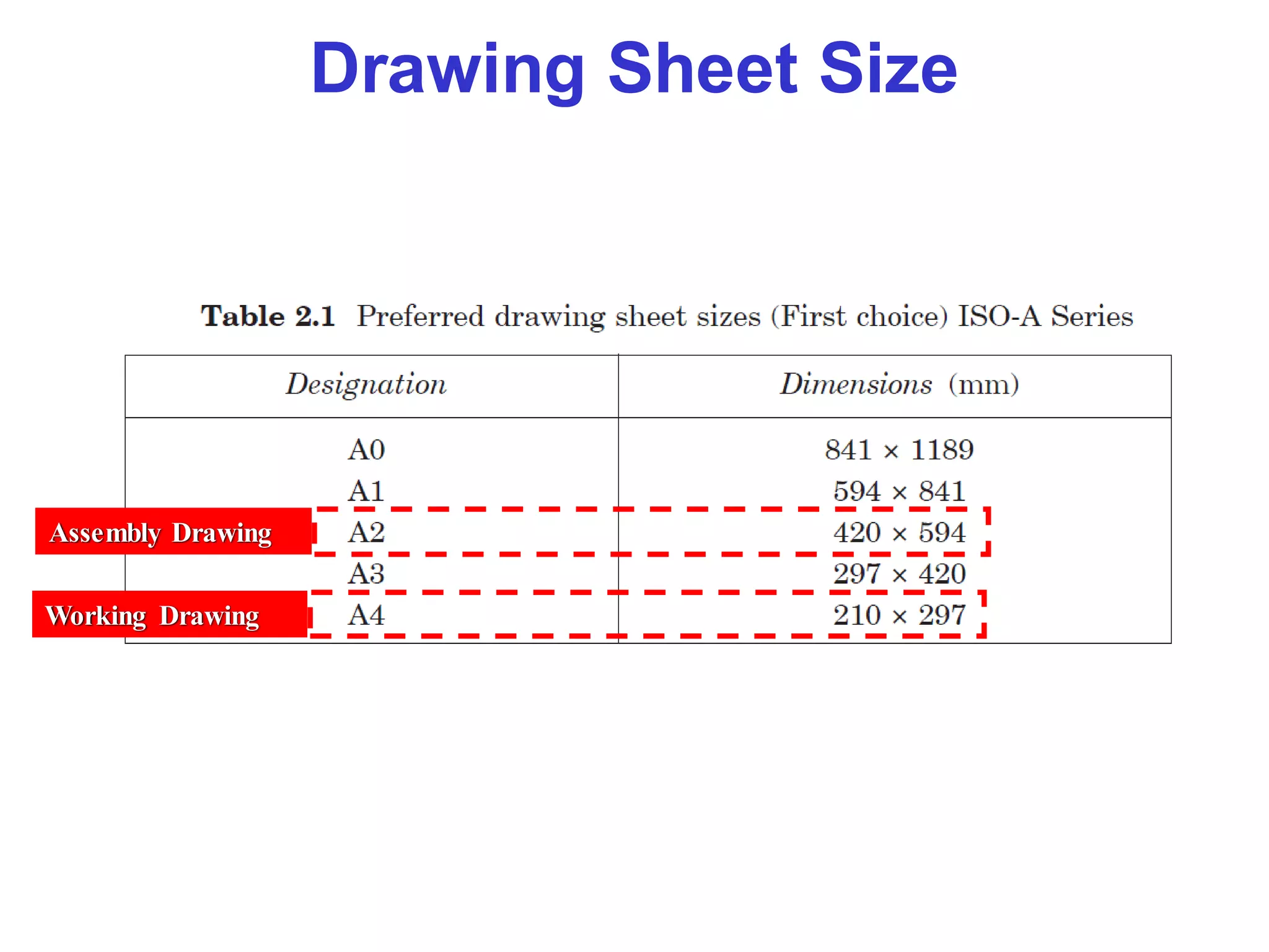
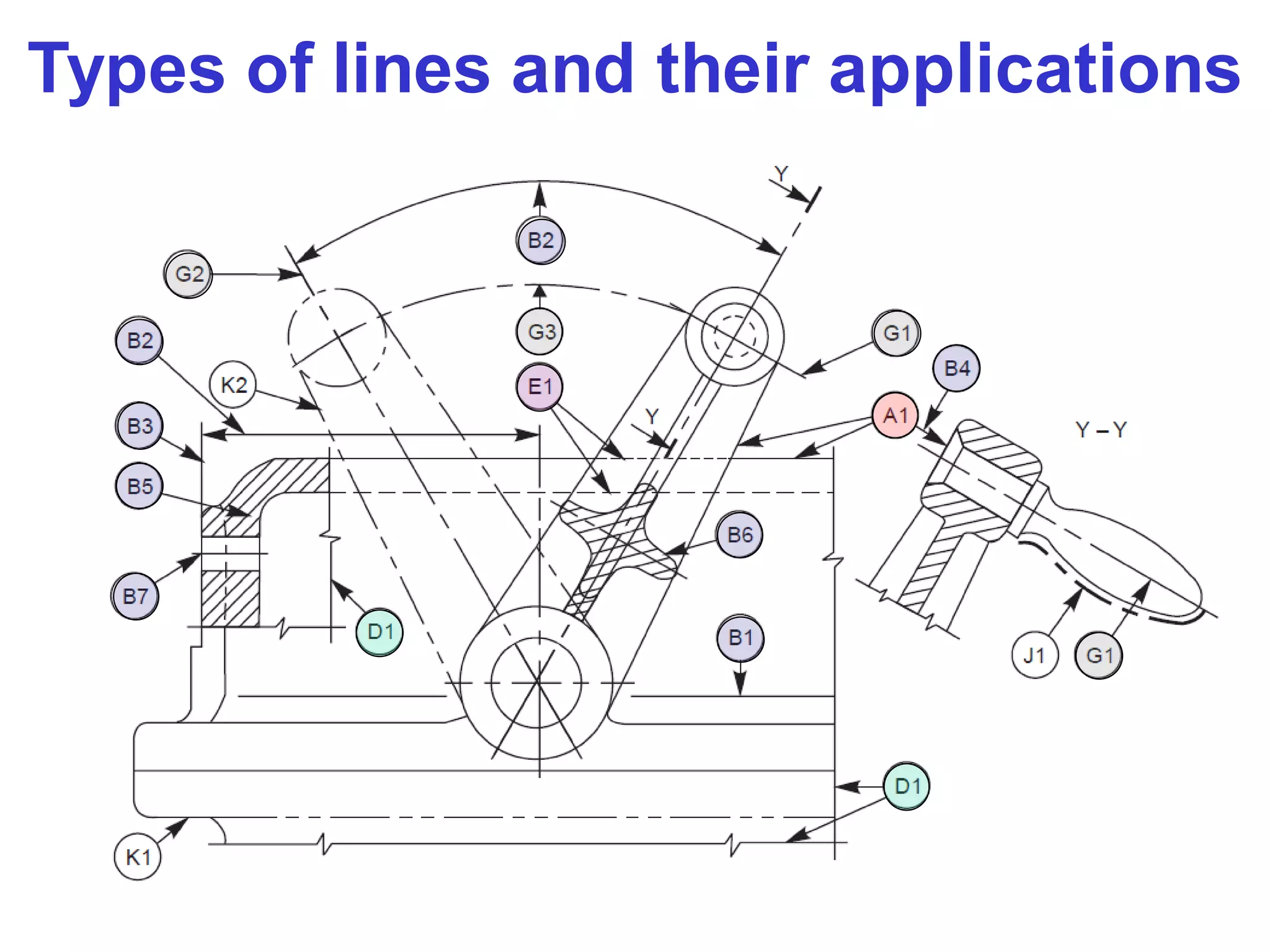
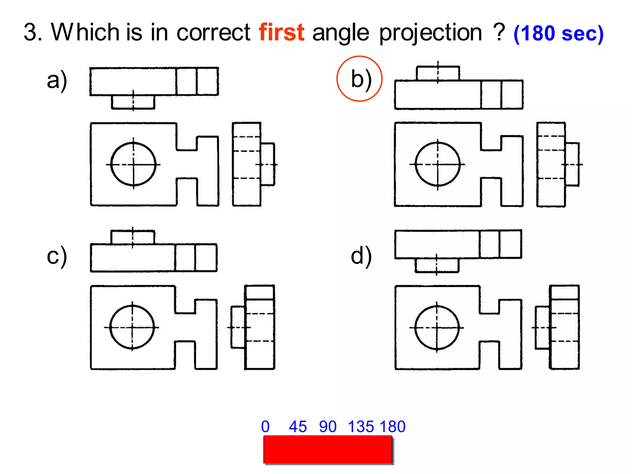
The document provides information on how to keep technical drawings clean and organized. It discusses proper drawing sheet size, types of projection systems including first angle and third angle, different types of projection views, and guidelines for selecting relevant views for technical drawings. Key topics include using appropriate line types for different elements, selecting front and side views that show the most important features with few hidden lines, and choosing the minimum number of views needed to fully represent the object being drawn. Following standardized technical drawing practices helps create clear, informative drawings.
7. PROJECTION SYSTEMS
1. First angle system
2. Third angle system
First Quadrant
Third
Quadrant
- European country
- ISO standard
- Canada, USA,
Japan, Thailand
13. 3. Which is in correct first angle projection ? (180 sec)
a) b)
c) d)
45 90 135 180
0
14. 4. Which is in correct third angle projection ? (180 sec)
a) b)
c) d)
45 90 135 180
0
15. 5. Which is a wrong 3rd angle orthographic views ?
(180 sec)
45 90 135 180
0
a) b)
c) d)
16. VIEW SELECTION STEPS
1. Orient the object to the best position
relative to a glass box.
2. Select the front view.
3. Select adjacent views.
17. STEP 1 : Orient the Object
The object should be placed in its natural position.
NO !
The object should presents its features in actual
size and shape in orthographic views.
GOOD
18. STEP 2 : Select a Front View
The object’s longest dimension should be
presented as a width.
Inappropriate
First choice
GOOD
Second choice
Waste more space
19. Inappropriate
The adjacent views that are projected from the
selected front view should appear in its natural
position.
STEP 2 : Select a Front View
20. STEP 2 : Select a Front View
Choose the view that have the fewest number of
hidden lines.
GOOD Inappropriate
21. STEP 3 : Select an Adjacent View
GOOD
Inappropriate
Inappropriate
GOOD
Choose the view that have the fewest number of
hidden lines.
22. Choose the minimum number of views that can
represent the major features of the object.
STEP 3 : Select an Adjacent View
Necessary
Necessary
Hole’s location can be
specified on the same view.
Difficult to interprete.
Easy to understand
23. Choose the views that are suitable to a drawing
space.
STEP 3 : Select an Adjacent View
POOR
Not enough space
for dimensioning.
24. Choose the views that are suitable to a drawing
space.
STEP 3 : Select an Adjacent View
GOOD
25. Example : View selection
Shape description
Size description
F.V.
W D
✓
W
H
D
mislead to…
✓
✓
✓
✓
F.V. & T.V. Three views F.V. & R.S.V.
H
26. ONE-VIEW DRAWING
Flat part having a uniform thickness.
Unnecessary These 2 views provide only information
about the part thickness !
1 Thick
40. Drawing Reading
Rear tool post is generally used on capstan lathes, mainly for parting-off operations. It is fixed
on the cross-slide in the slots, provided at the rear side of the lathe