Downloaded 104 times


This document discusses isometric sketching and projection. It begins by explaining that orthographic views only show two dimensions, making them difficult for non-technical people to understand the object's shape. Pictorial projections show all three dimensions in one view, but do not show true sizes or hidden portions. Isometric projection positions the object so that the planes are equally inclined to the three principal planes, allowing dimensions to be measured. An isometric sketch of a cube is used to demonstrate the isometric axes, lines, and planes used to construct isometric views, which can then be dimensioned.
Introduction to pictorial sketching, showcasing the importance of understanding 3D views.
Comparison of orthographic views which are 2D and harder to interpret versus pictorial projections which are 3D and easier to understand.
Pictorial views do not accurately depict true shape, size and hidden aspects; used commonly in sales.
Definition of projection by drawing straight lines from an object to a plane, termed projectors.
Classification of projections into orthographic and pictorial, with emphasis on pictorial showing all dimensions.
Detailed explanation of isometric sketching, which is a type of pictorial drawing based on actual dimensions.
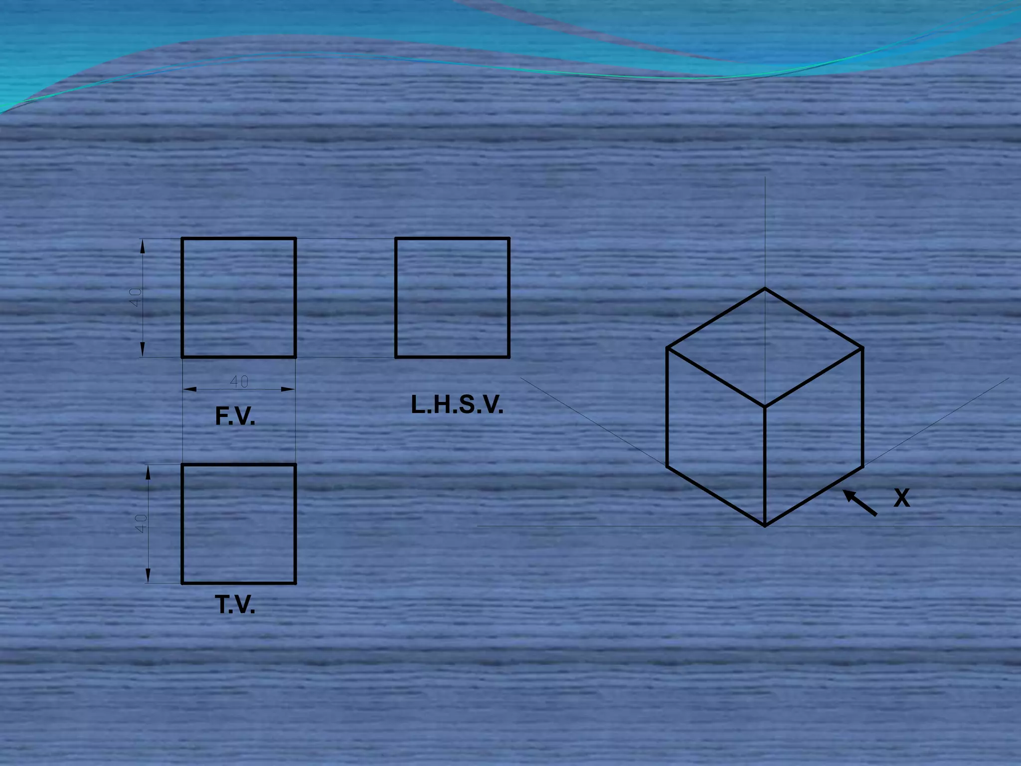
Illustration of isometric axes and how they relate to the orientation of a cube in isometric drawing.
Definition and explanation of isometric axes, lines, and planes used in isometric sketching.
Distinction between isometric drawing which uses true scale and isometric projection which uses isometric scale.
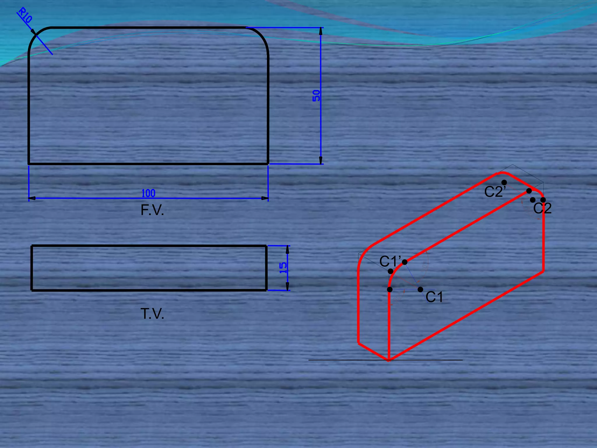
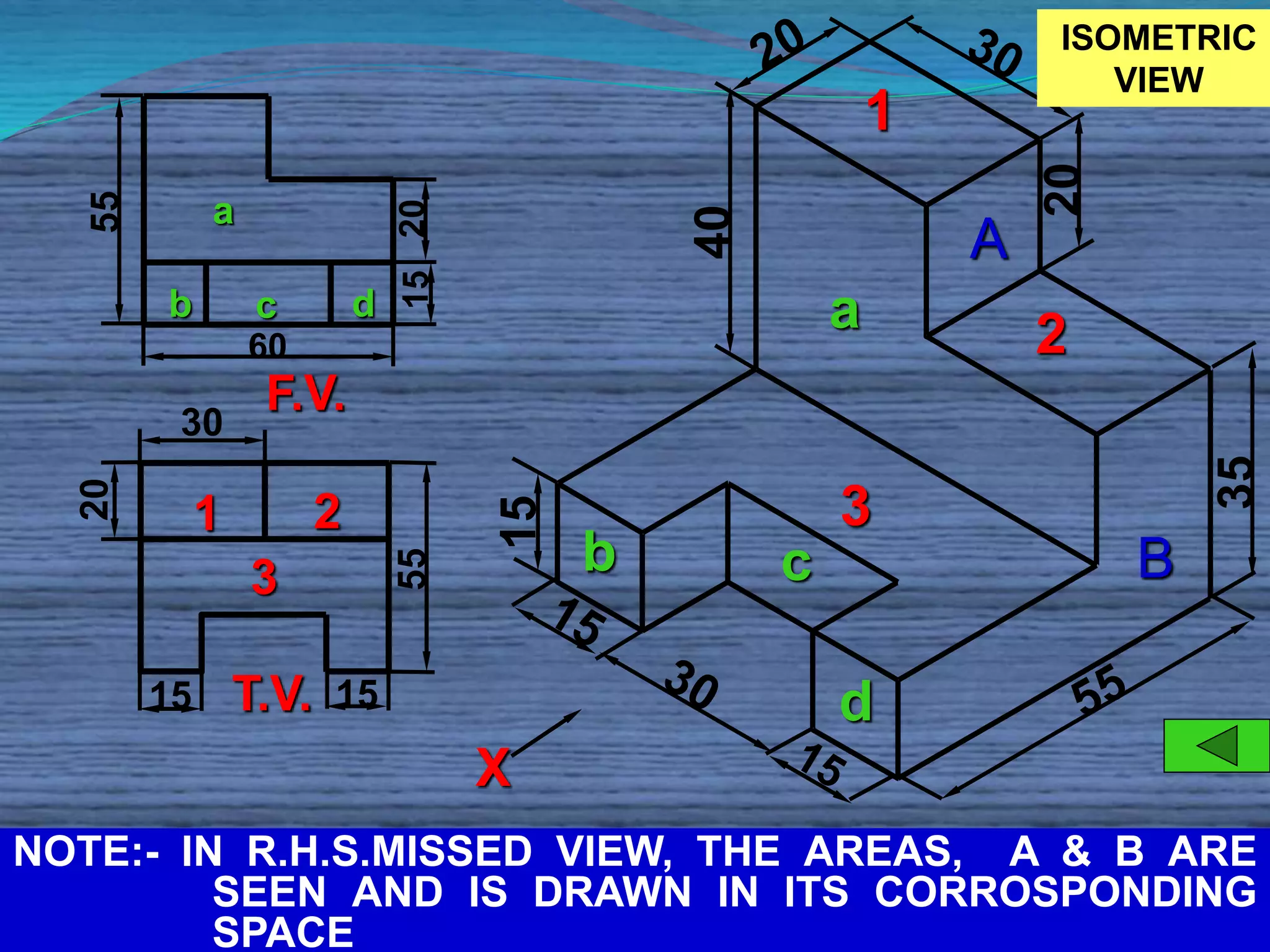
Representation of views in isometric drawing regarding front and top views (F.V., T.V.).
Continuation of view representation in isometric drawing, showcasing front and top views.
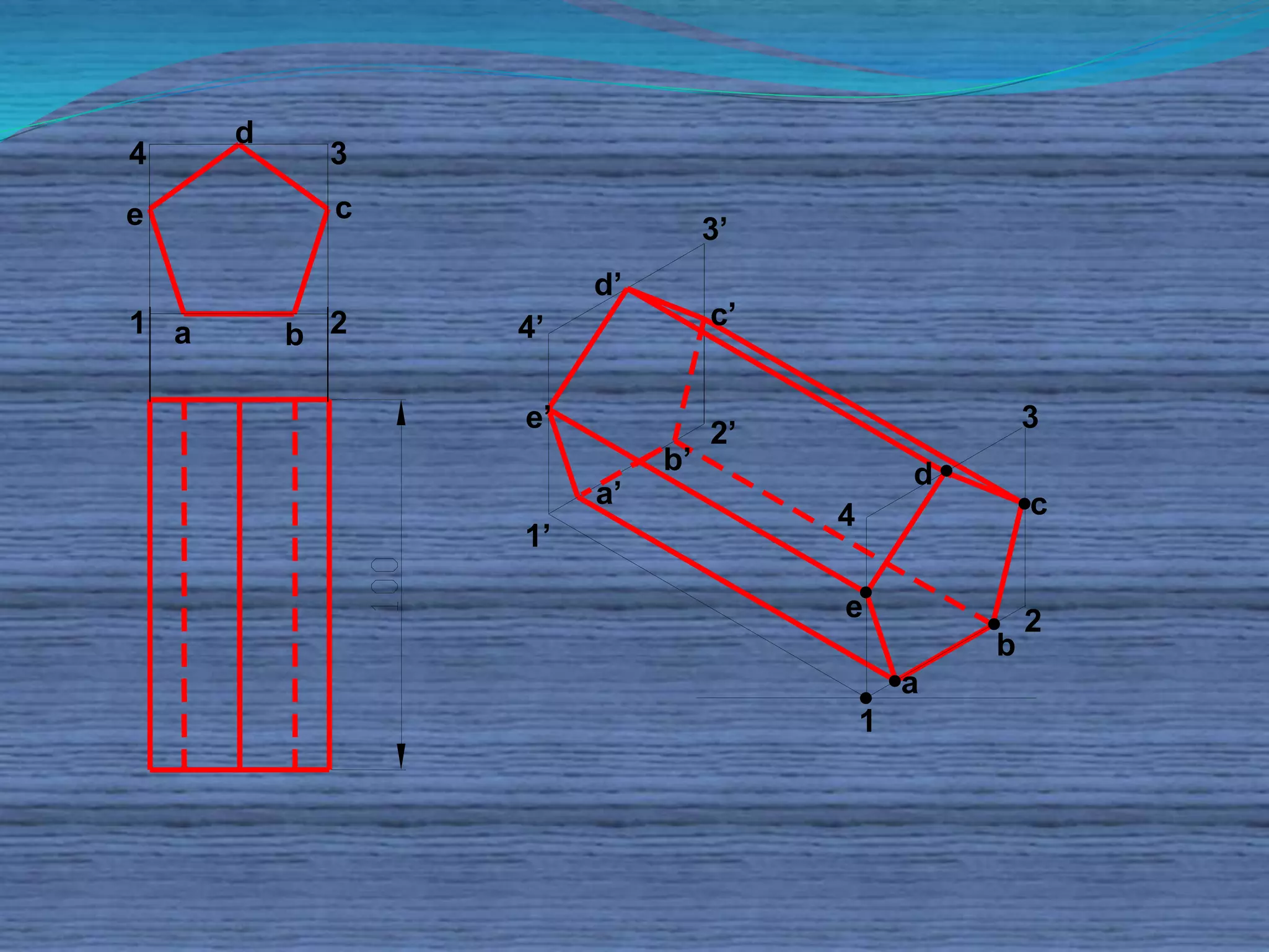
Additional representation of views with specific references to various elements and views in isometric.
Integration of front, top, and side views in isometric notation with labeled elements.
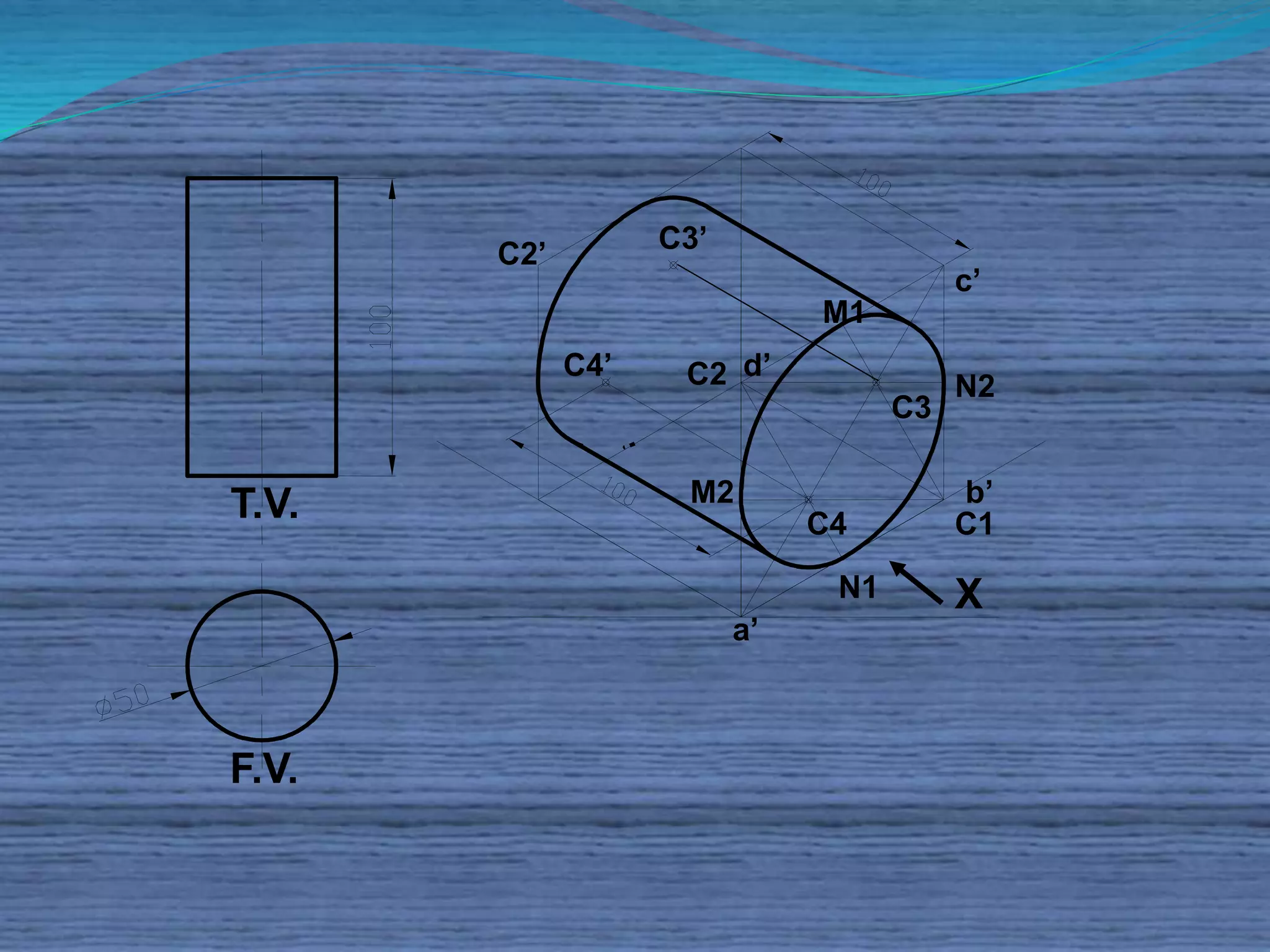
Analysis of final isometric views, noting key dimensions and corresponding spaces in the drawing.


