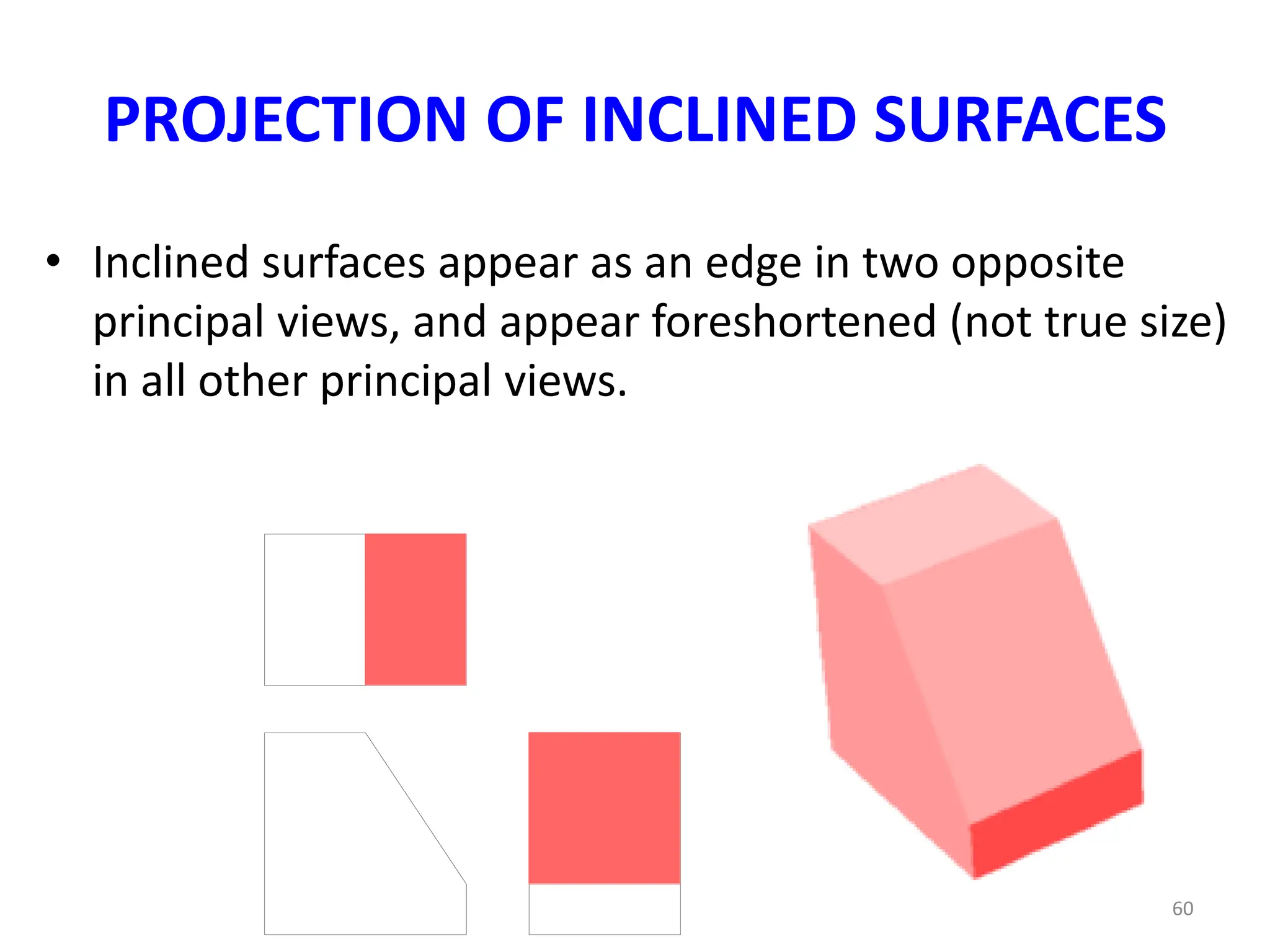
This document provides an overview of multi-view drawing concepts including:
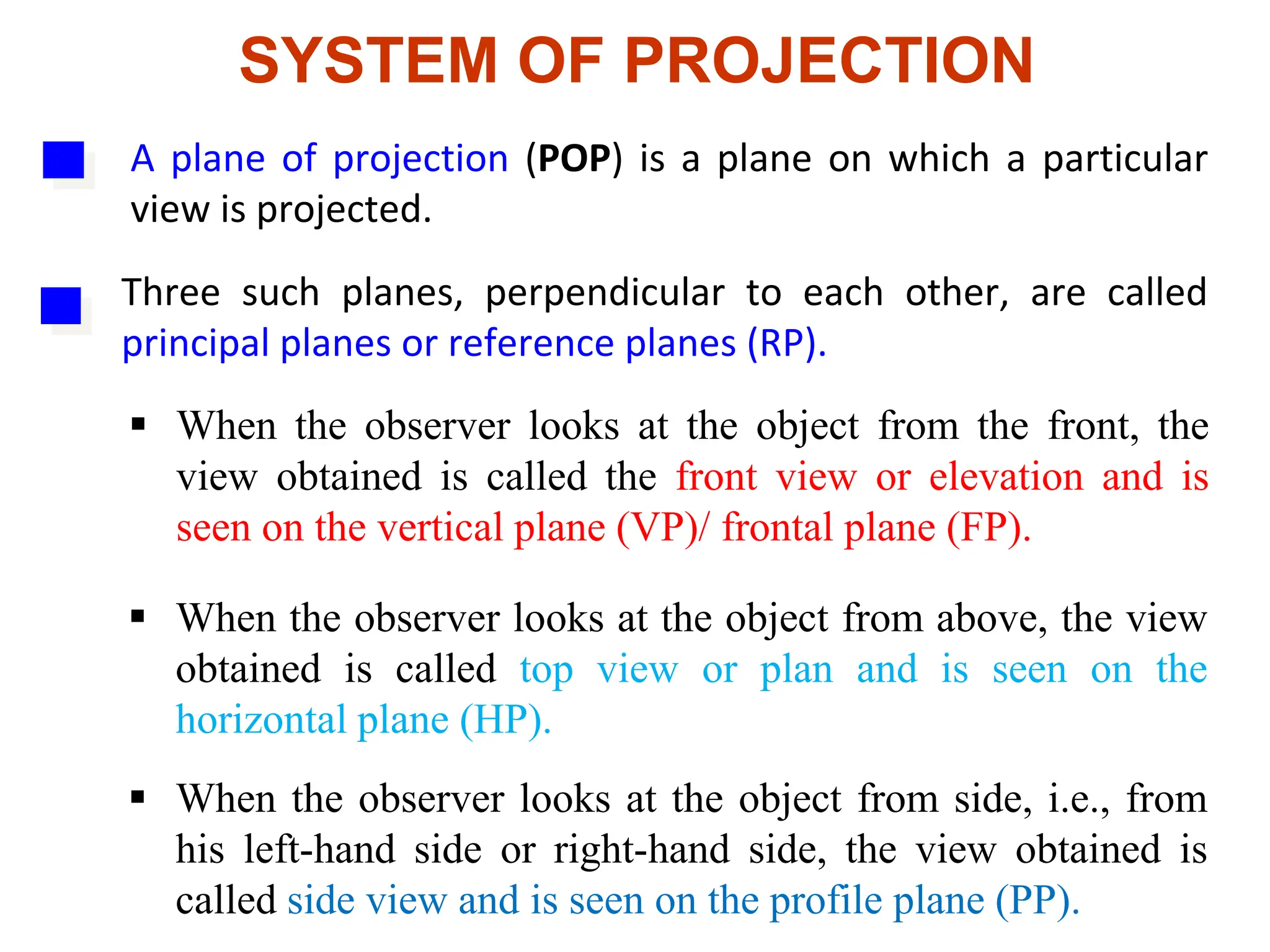
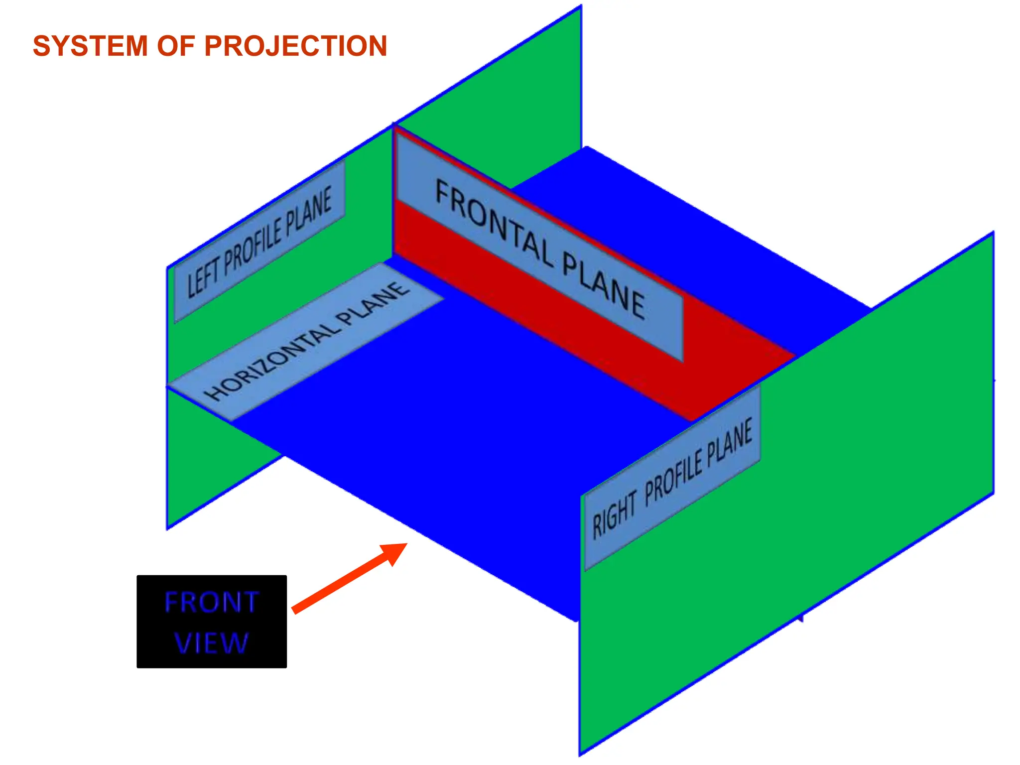
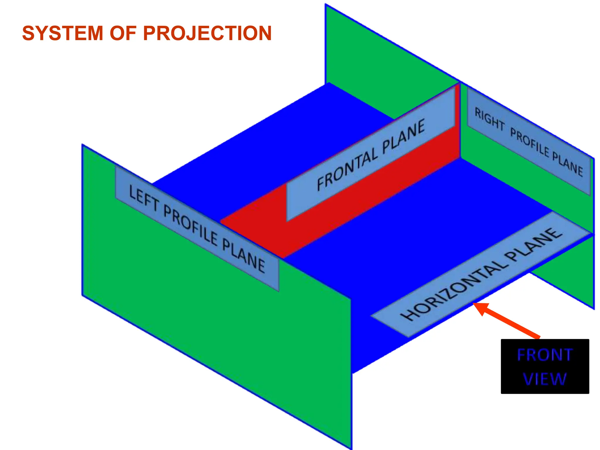
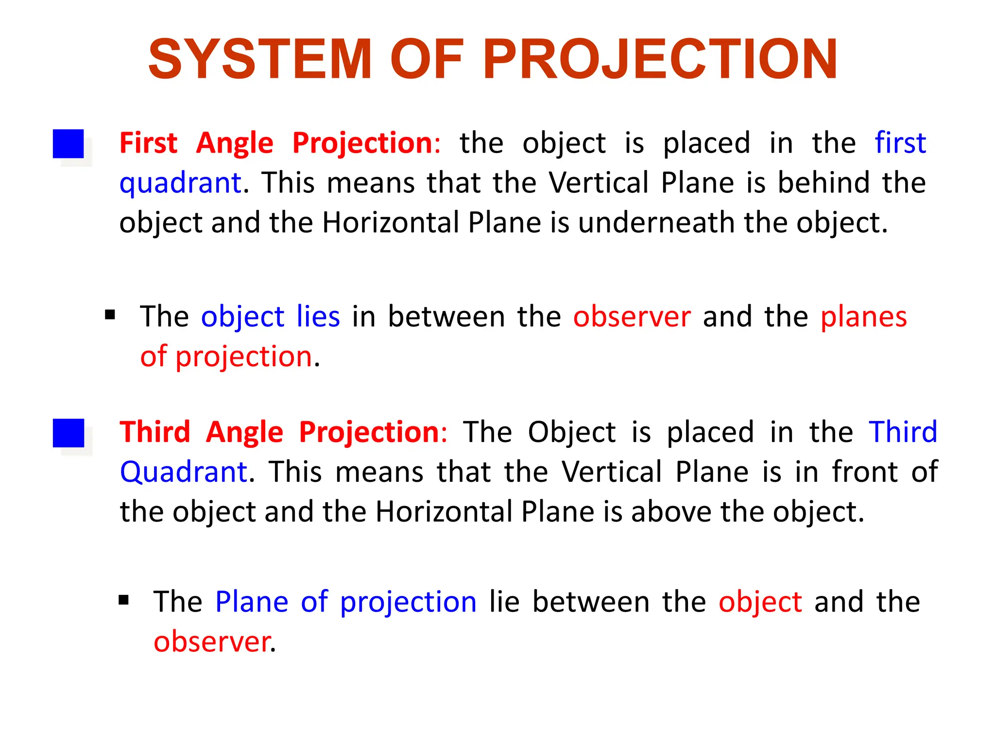
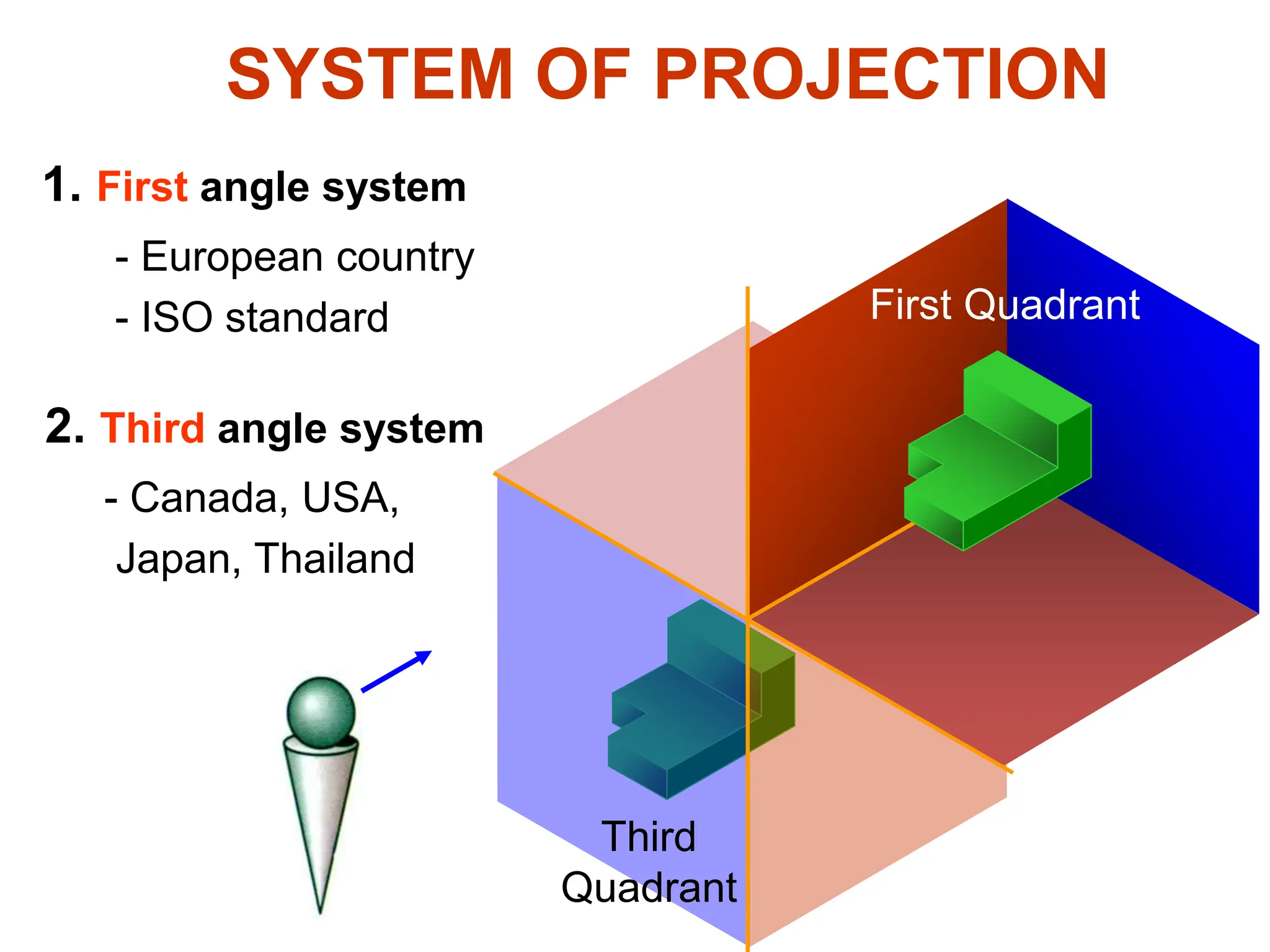
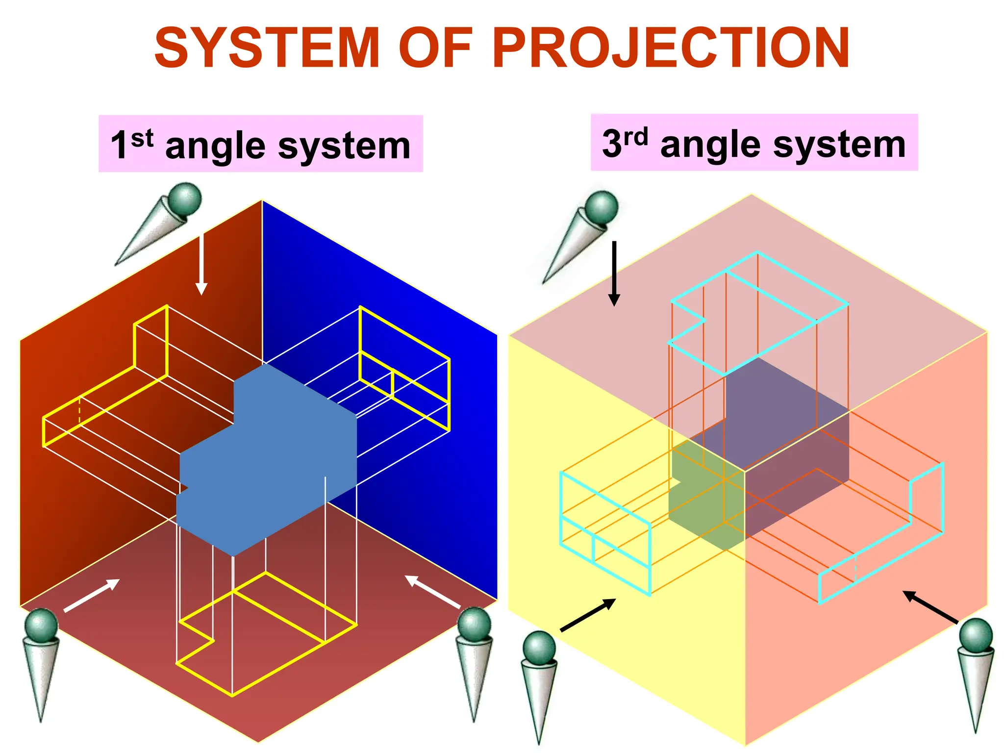
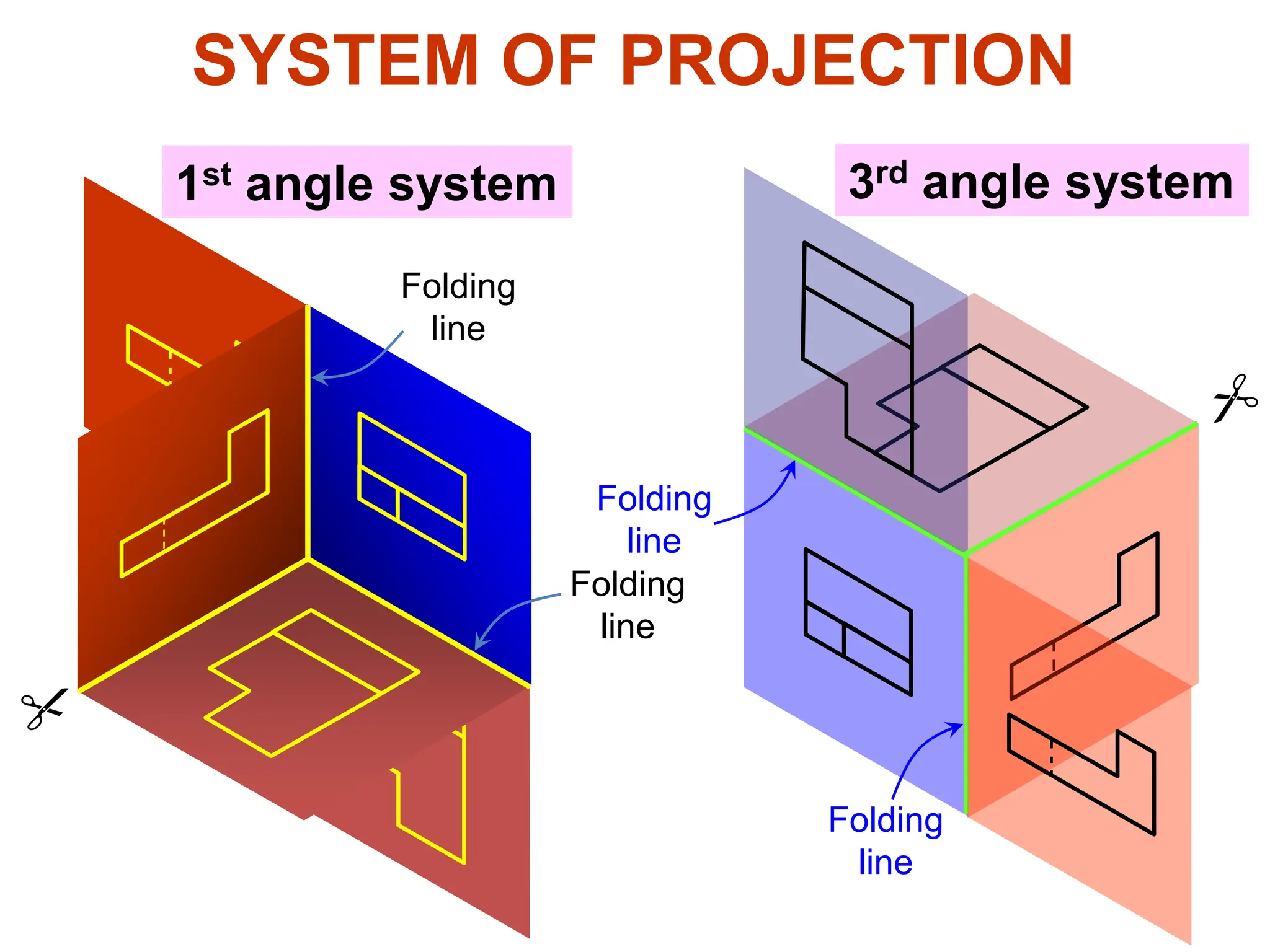
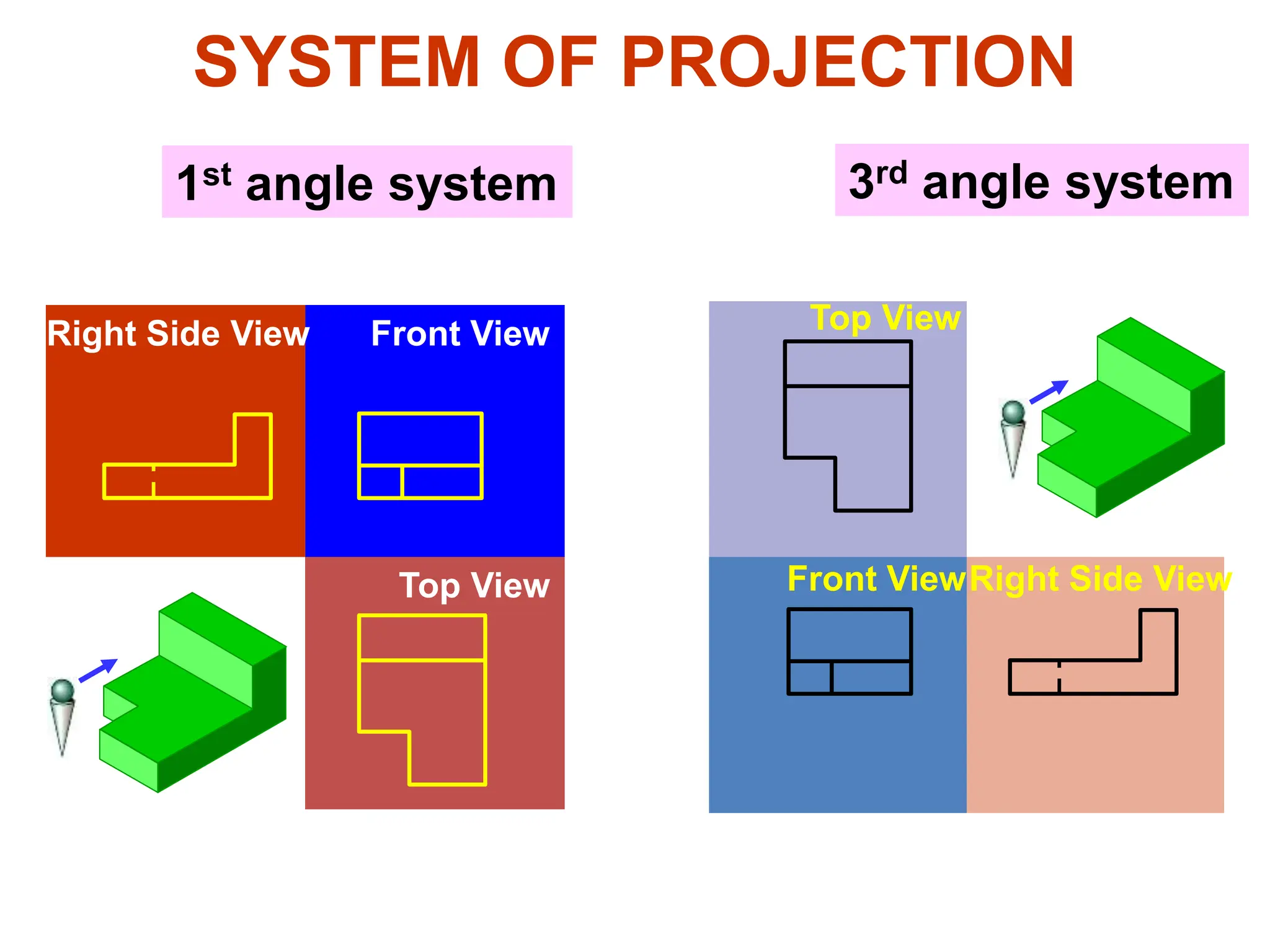
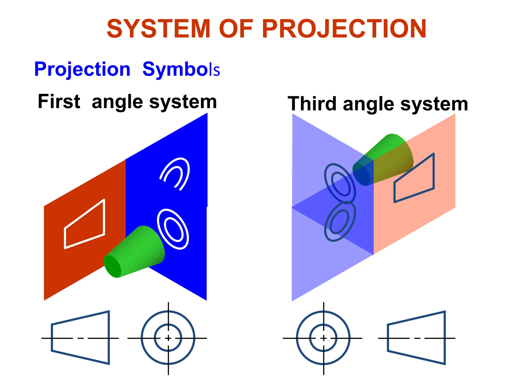
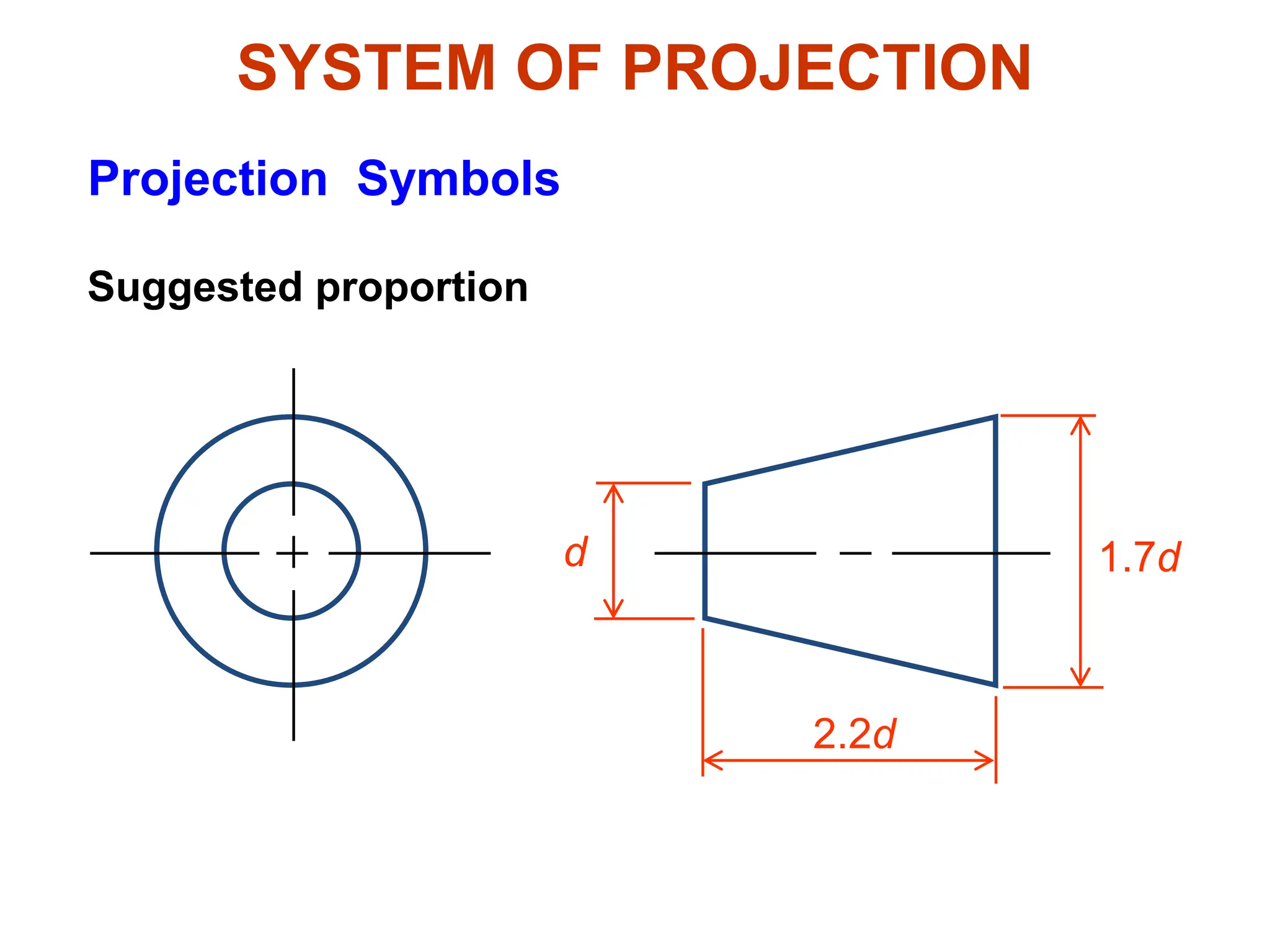
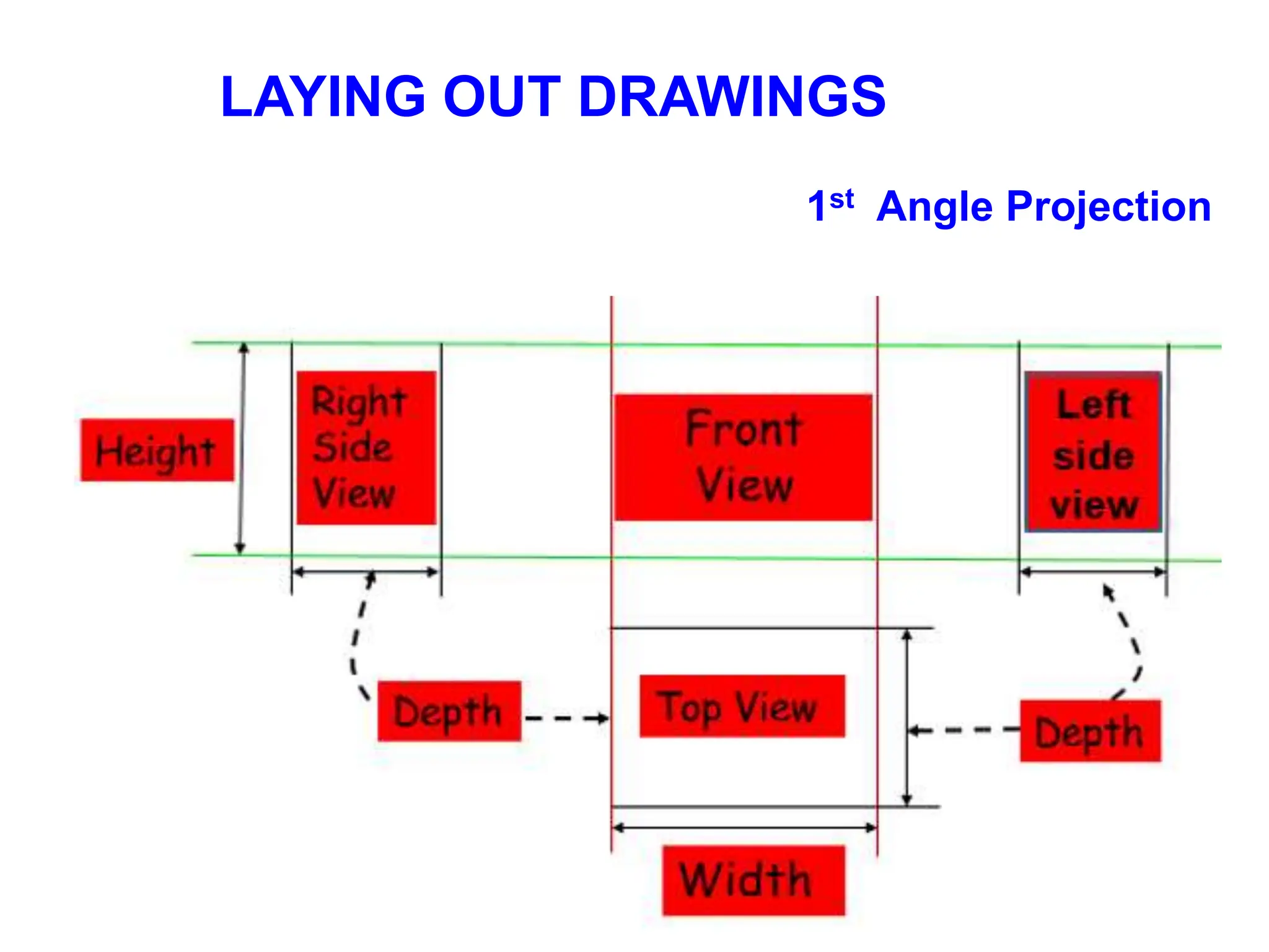
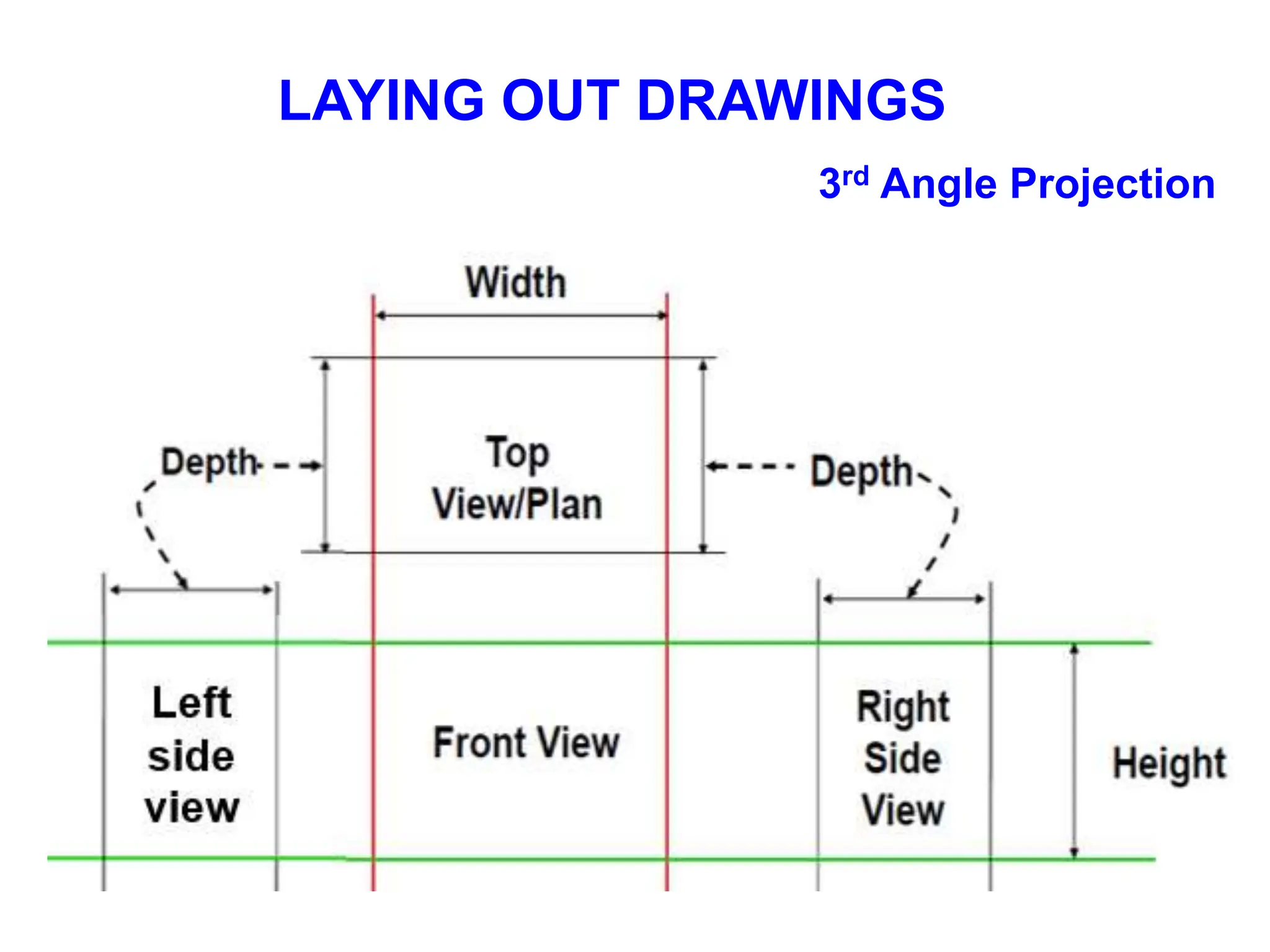
1. It describes the first angle and third angle projection systems used to project views onto principal planes.
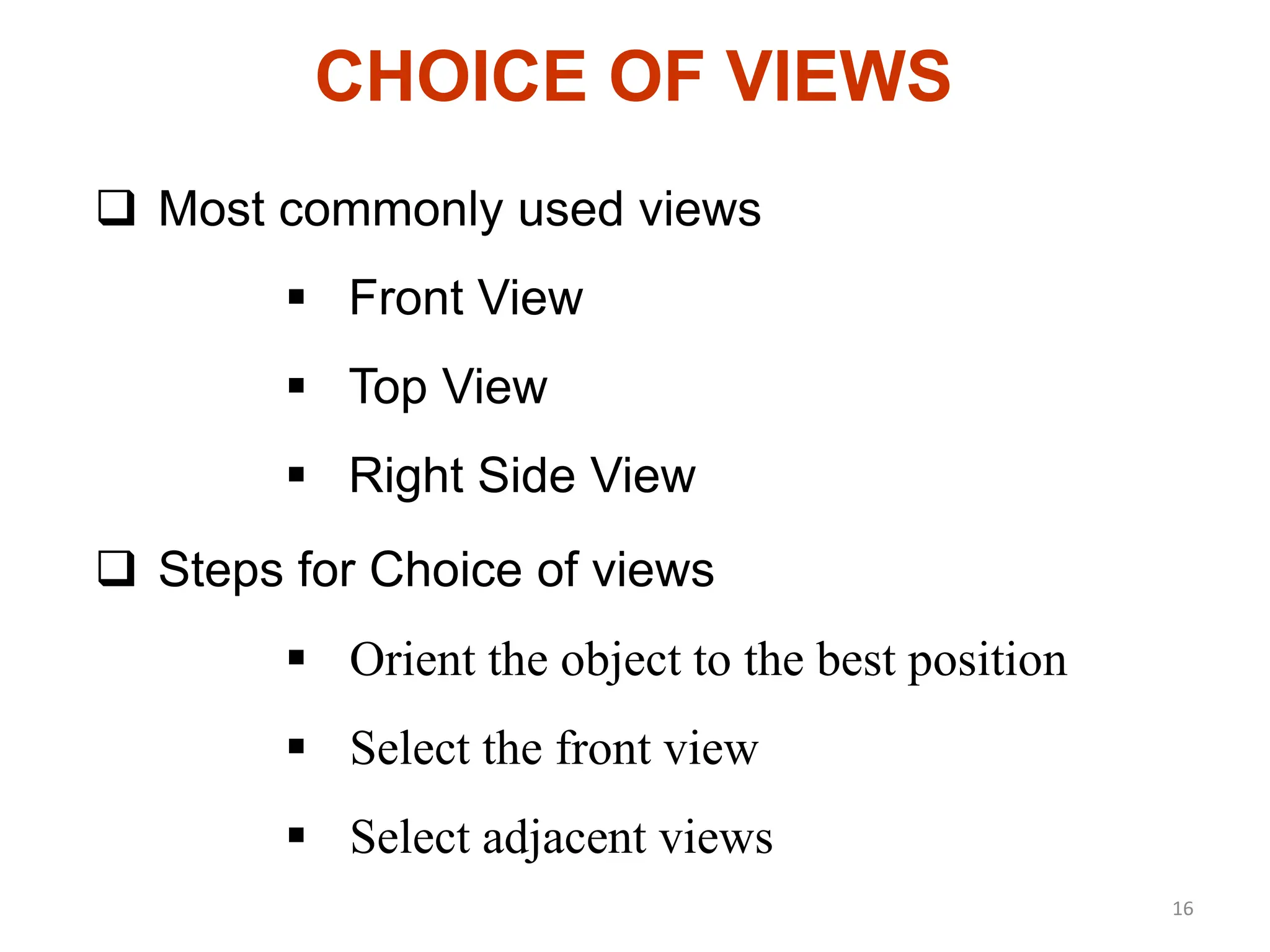
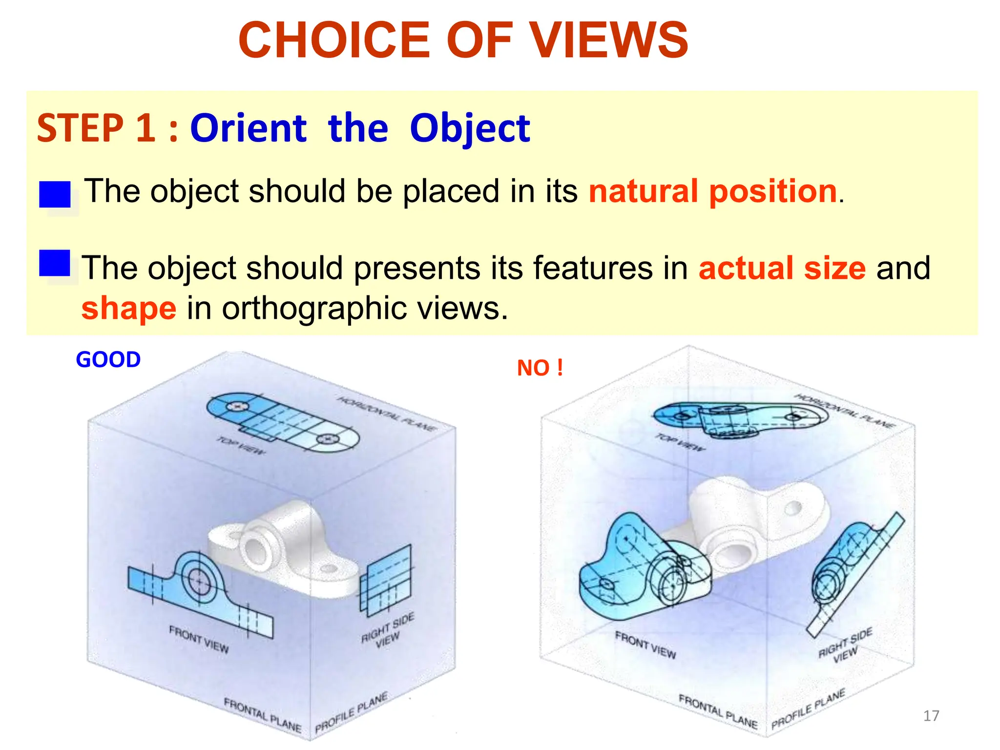
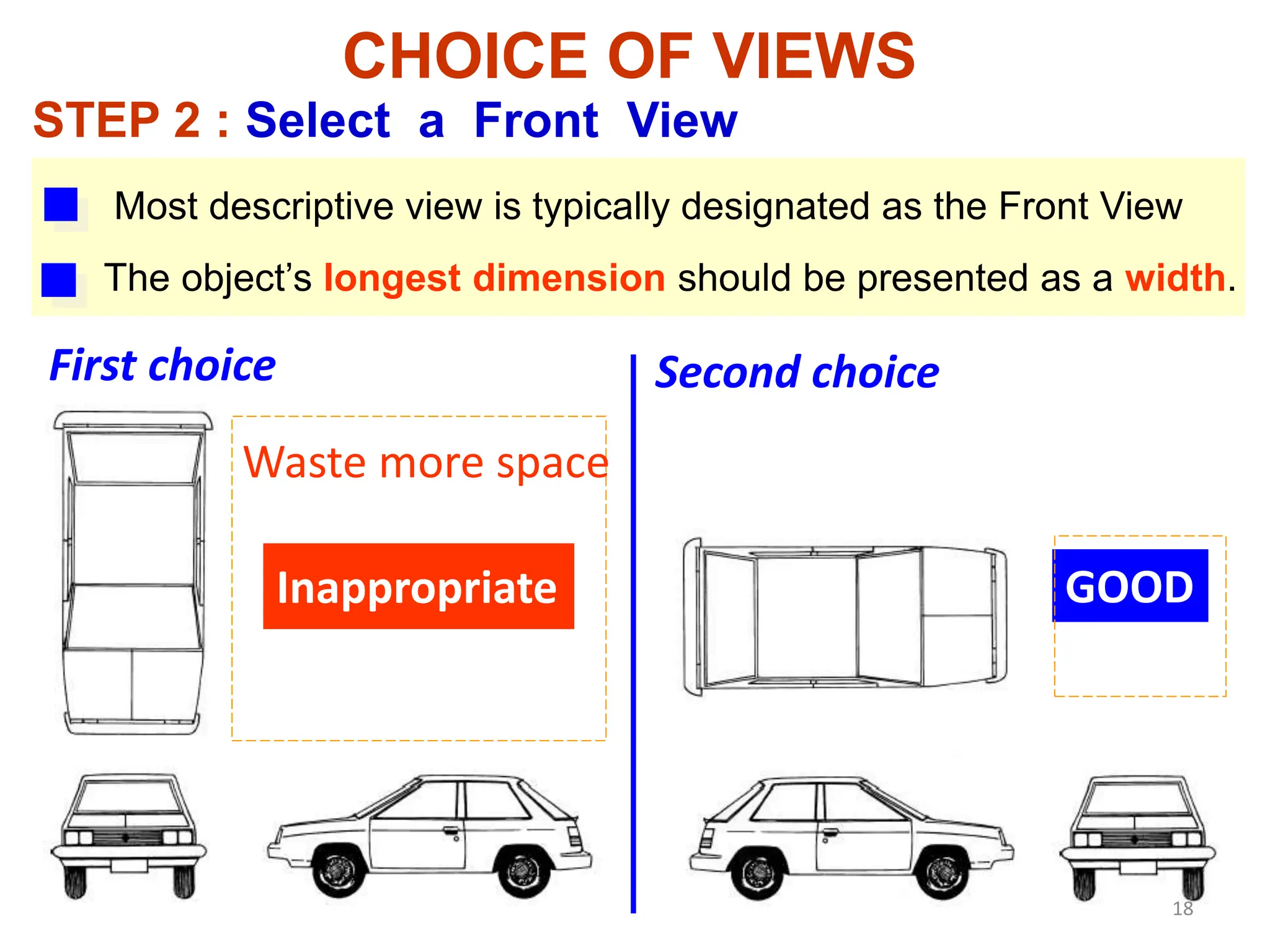
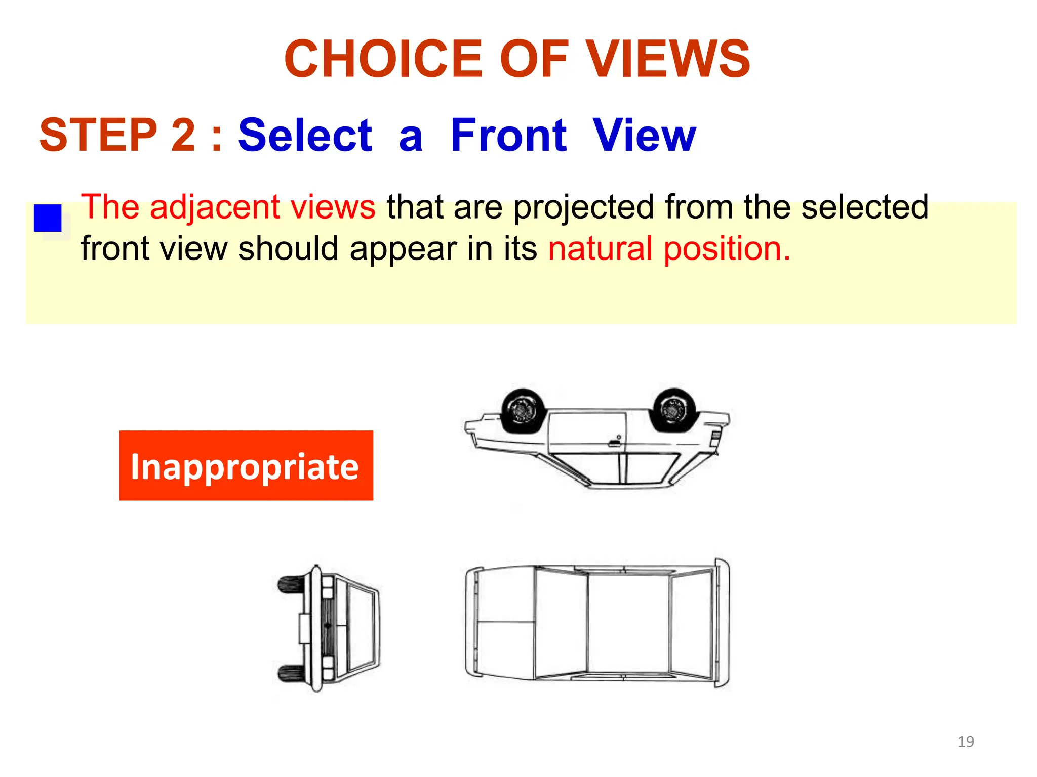
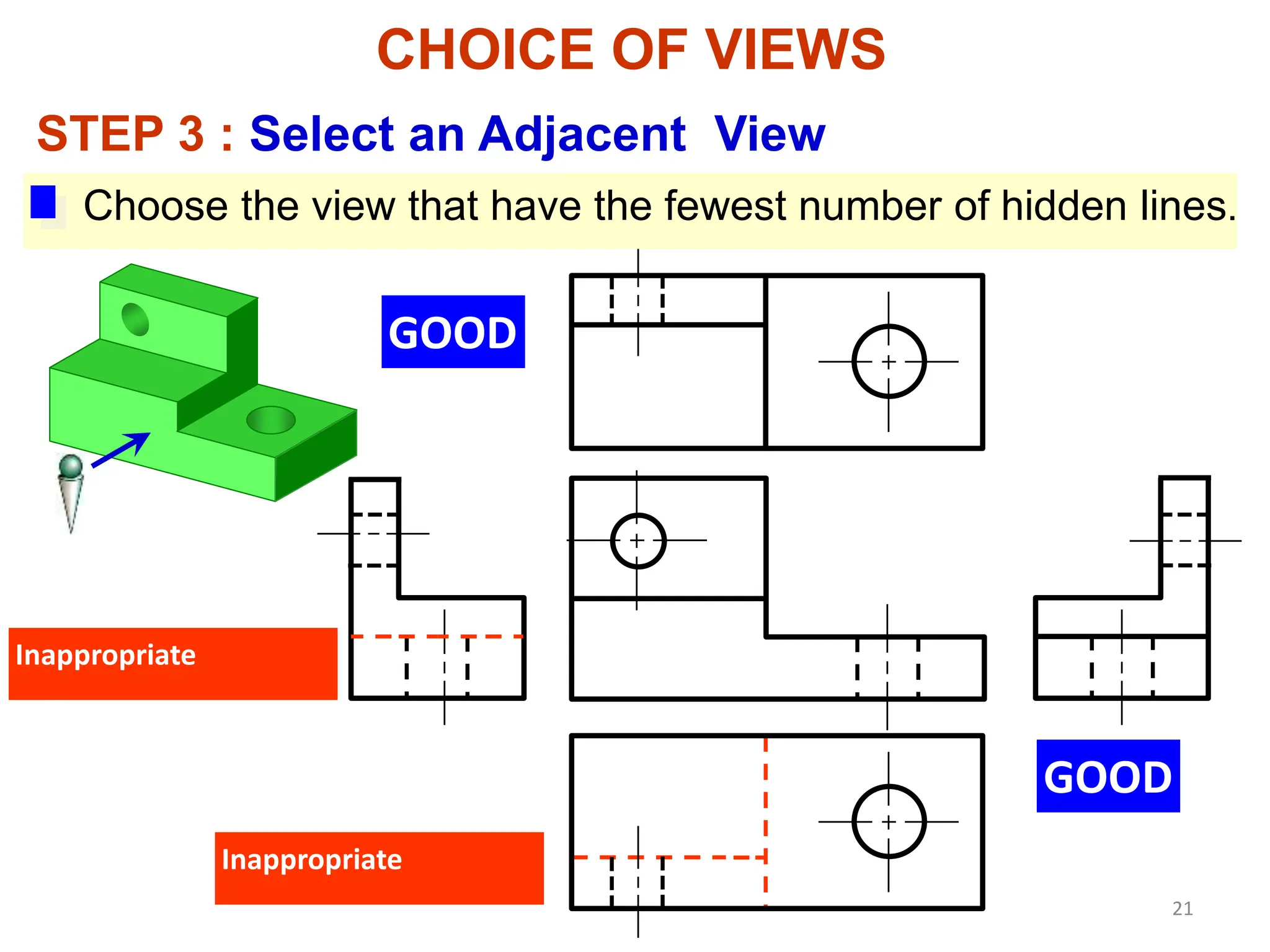
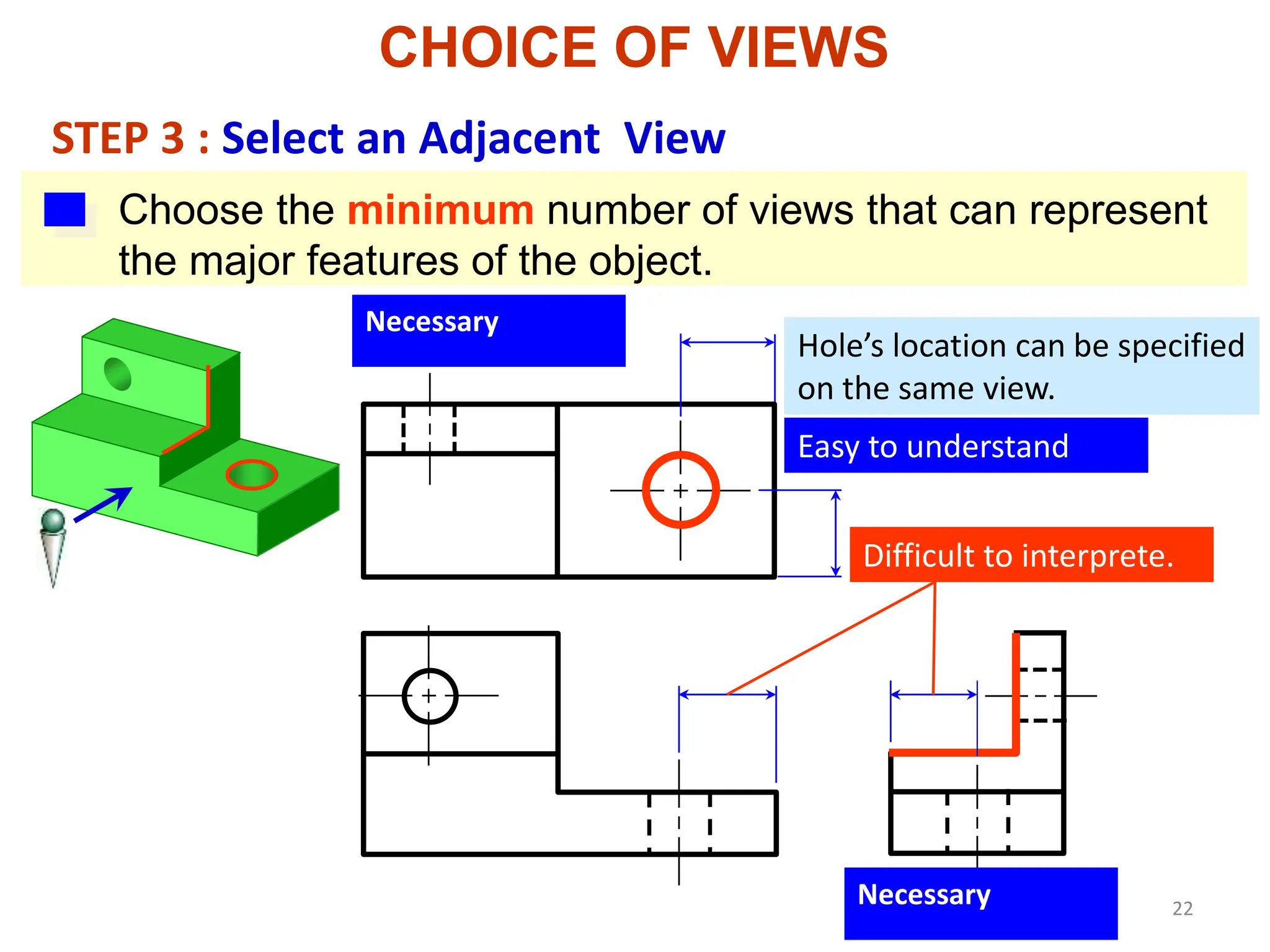
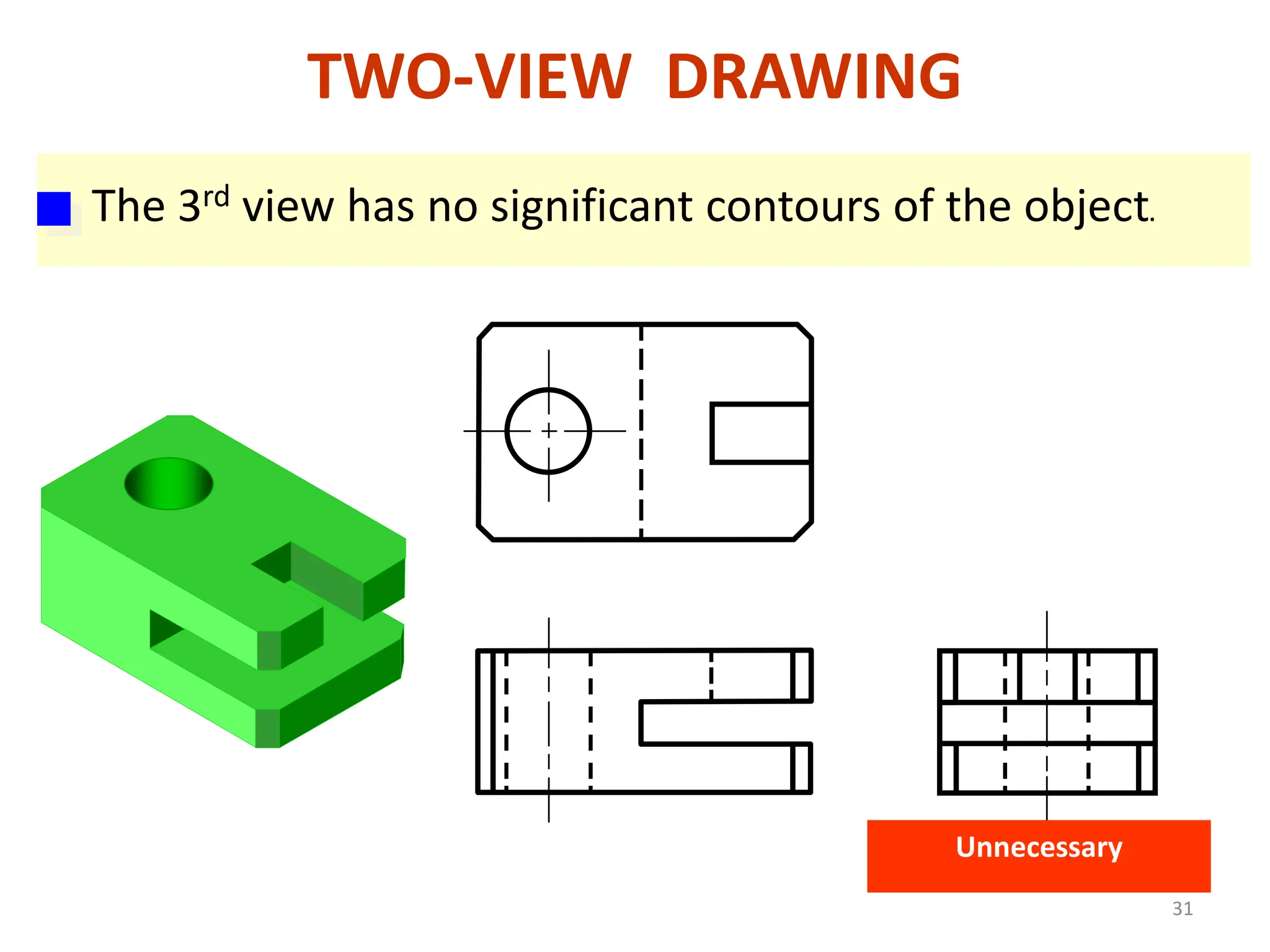
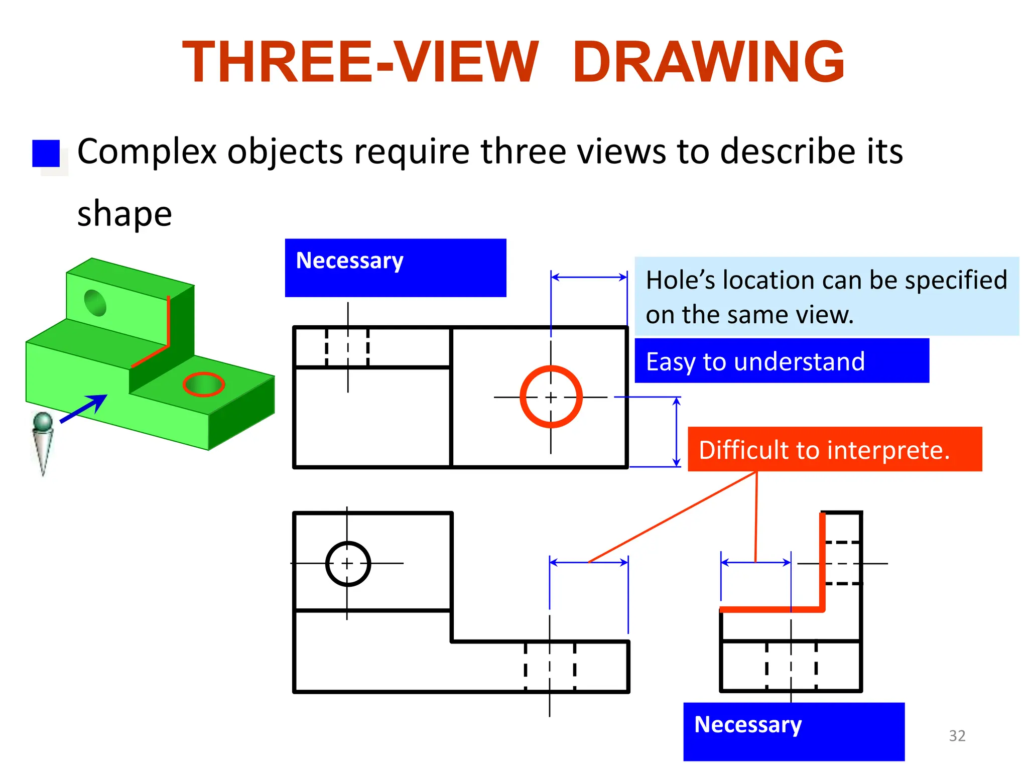
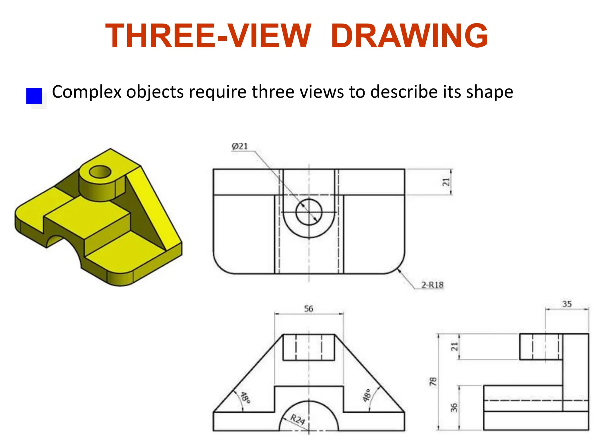
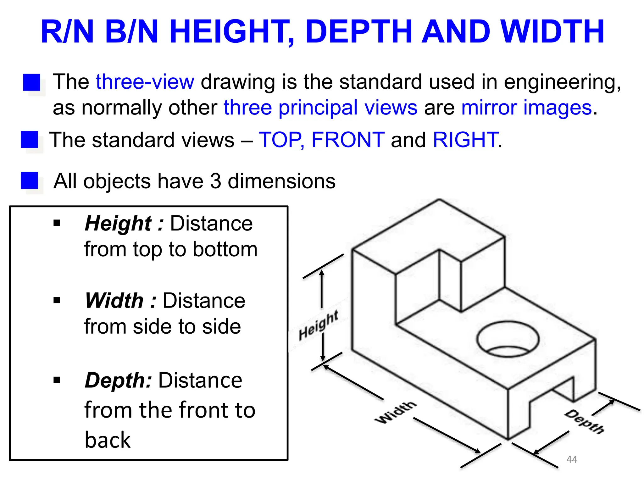
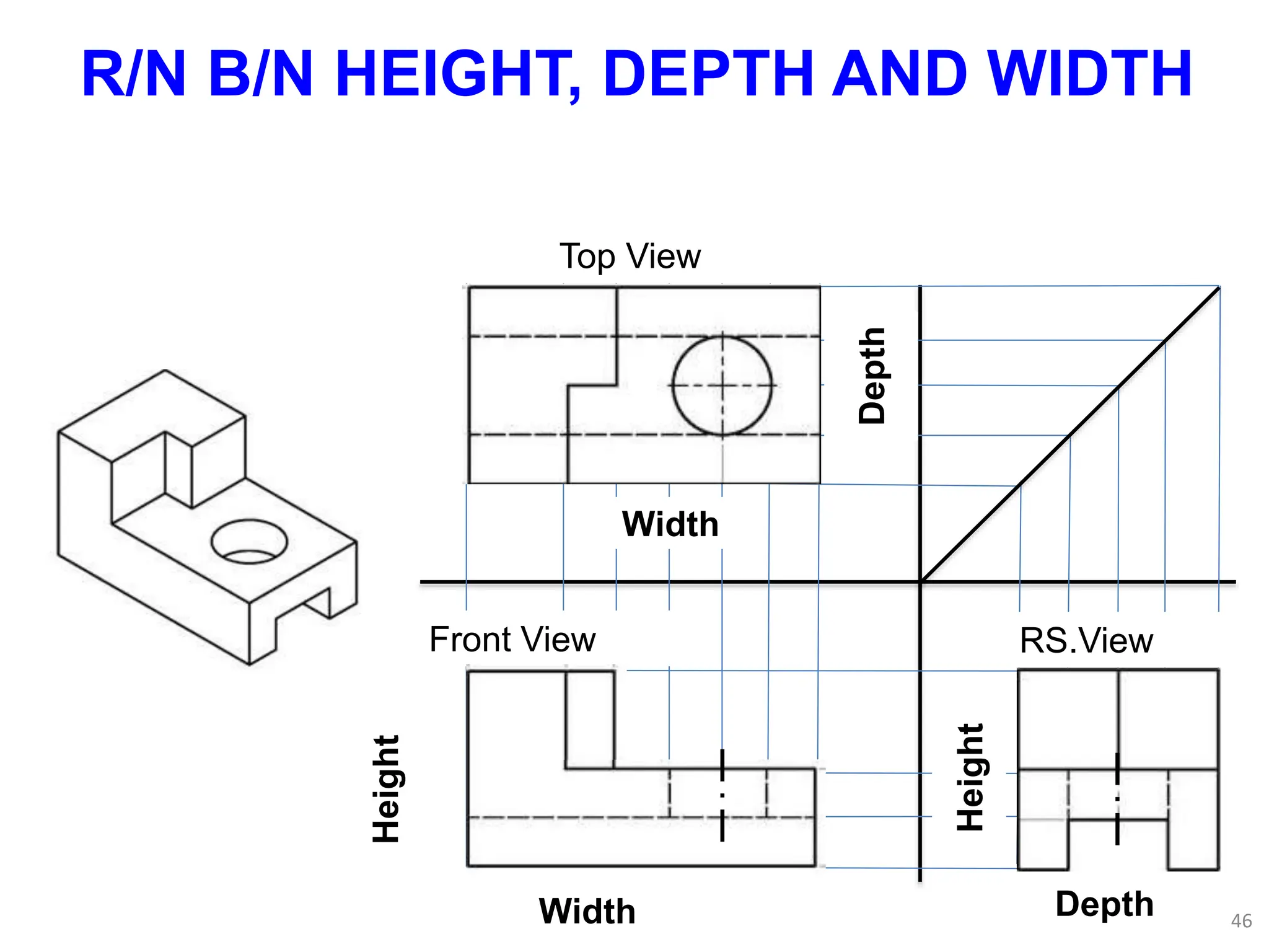
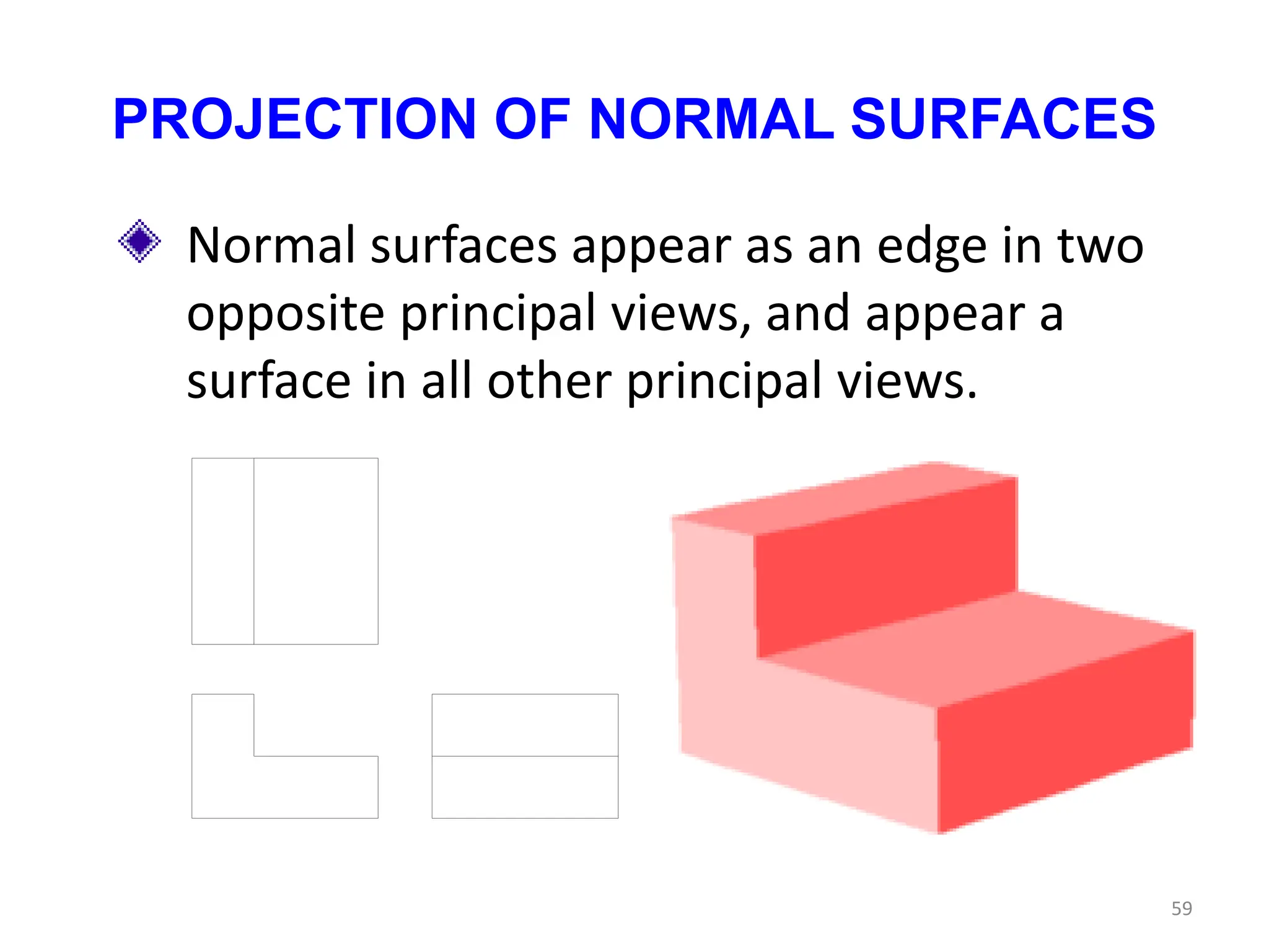
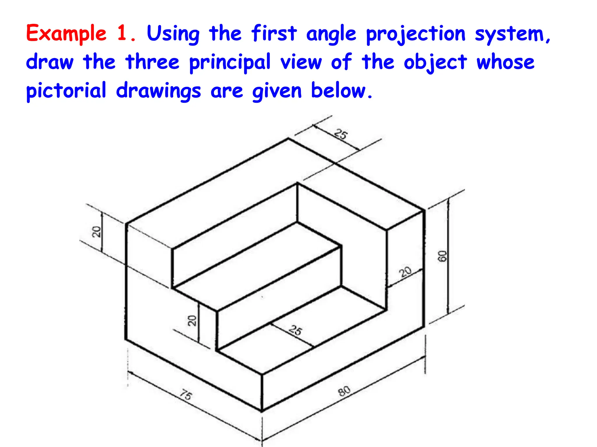
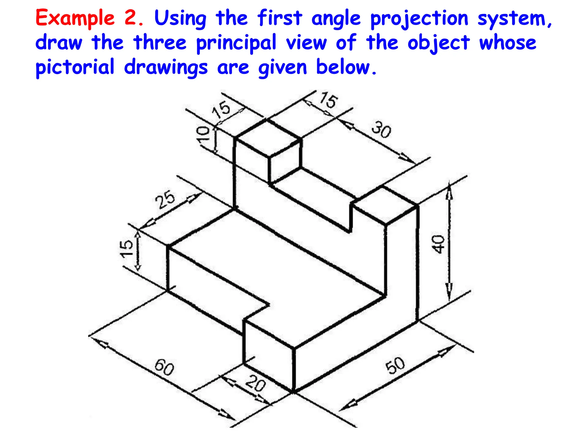
2. Guidelines are given for selecting appropriate views such as the front, top, and side views to fully represent an object.
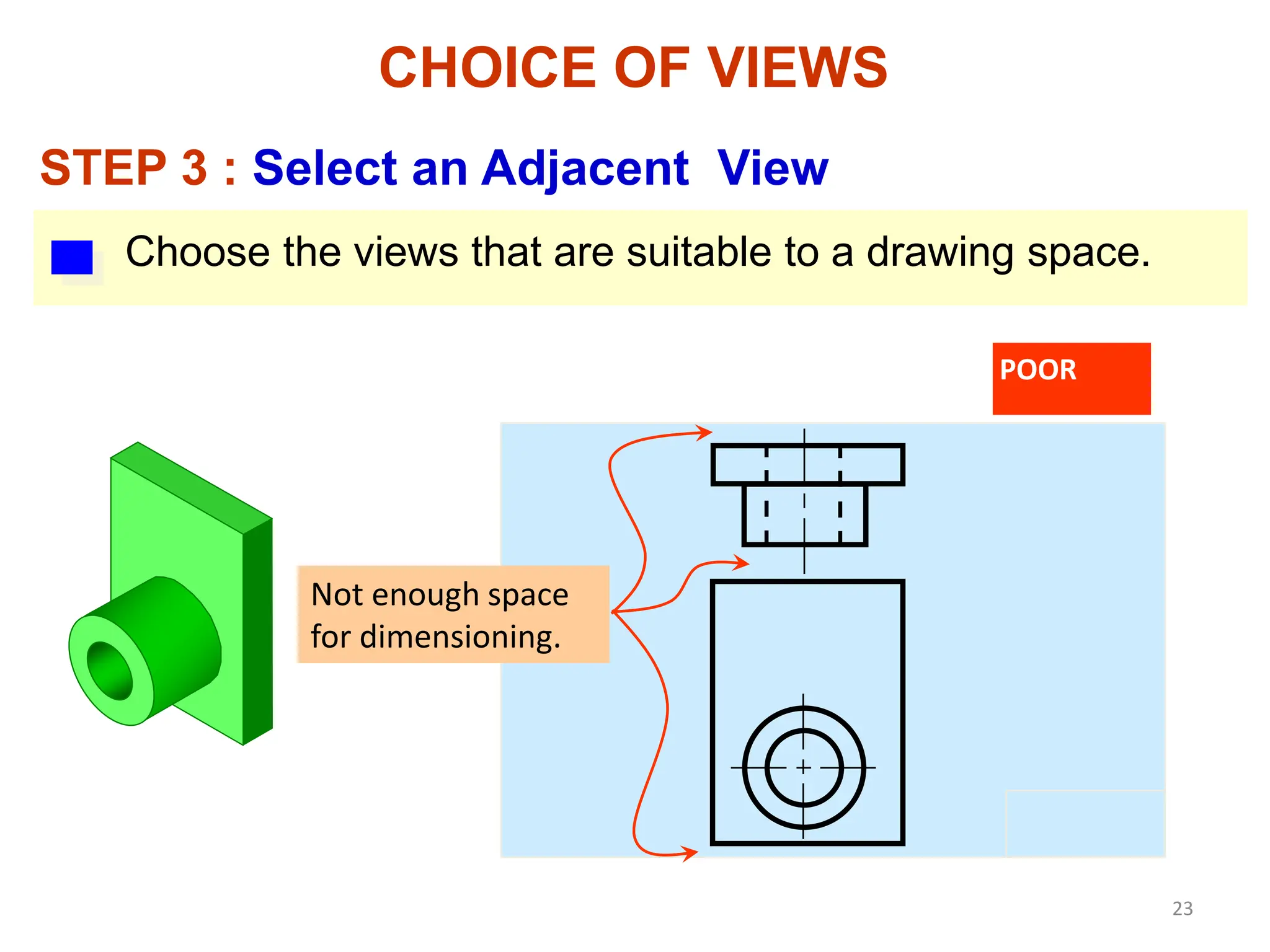
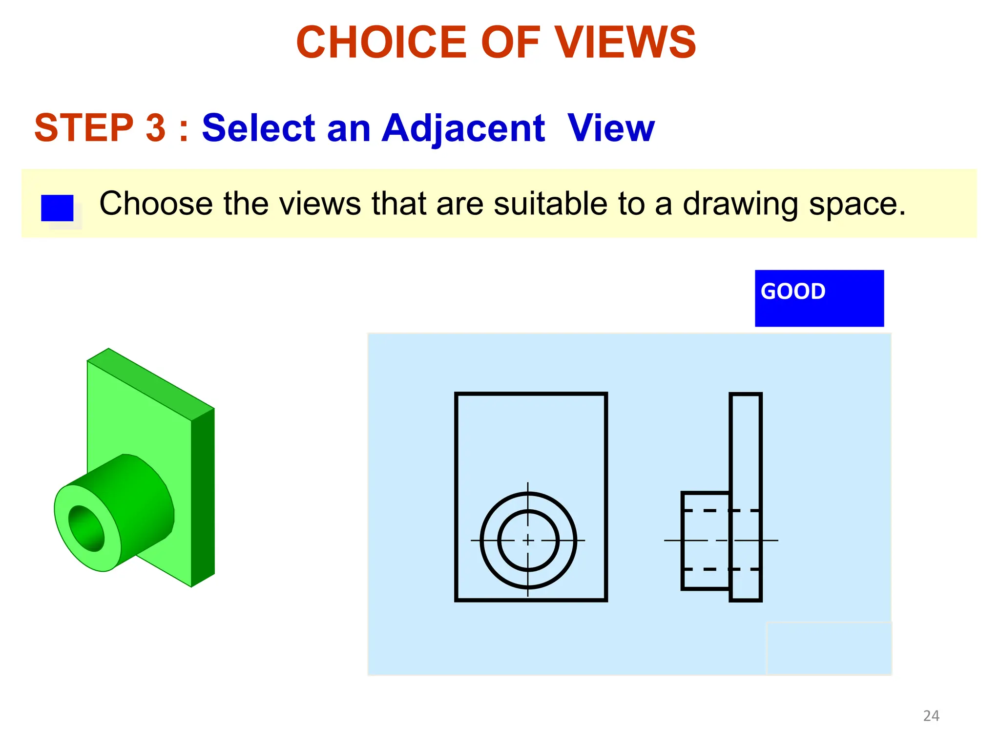
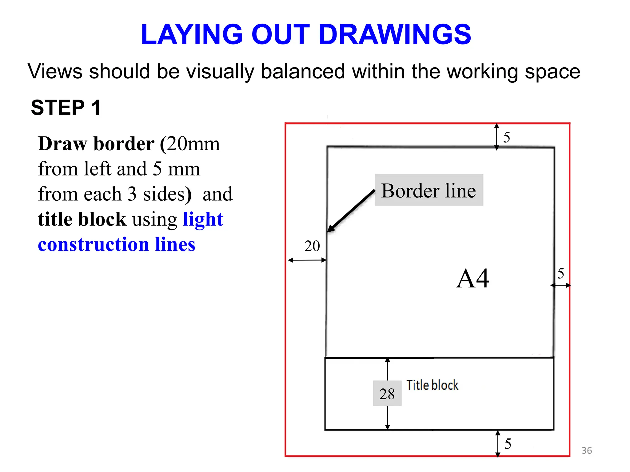
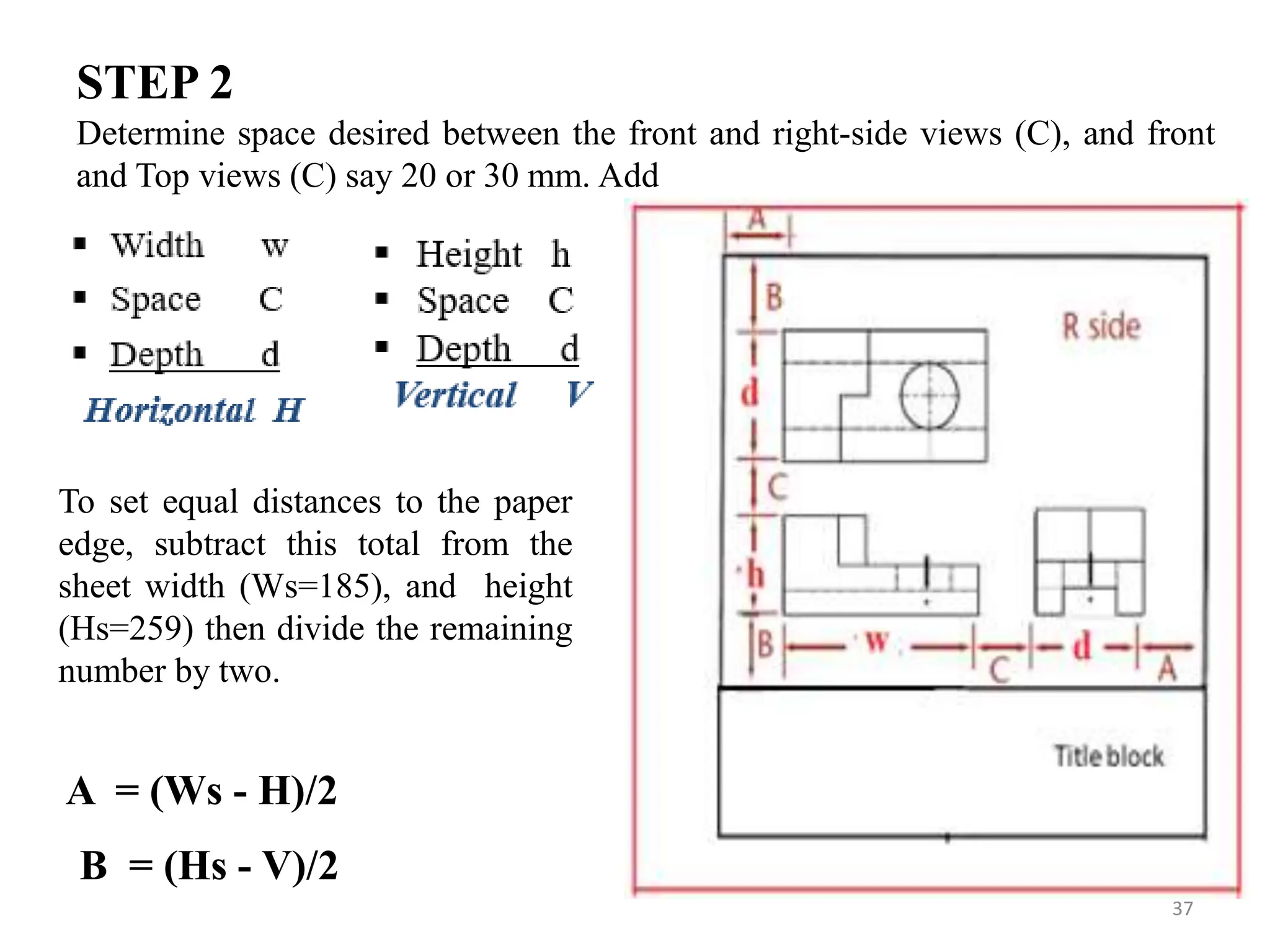
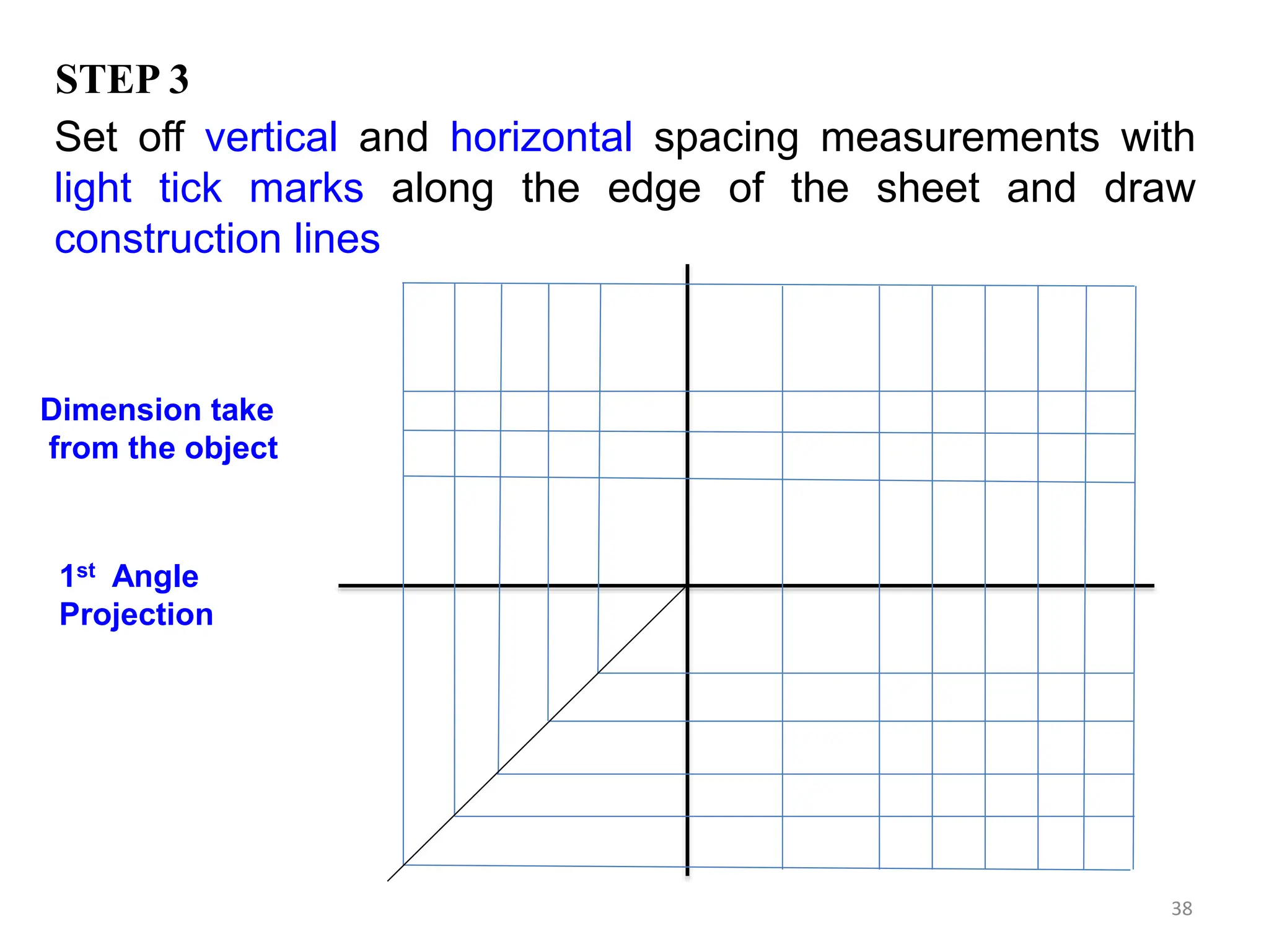
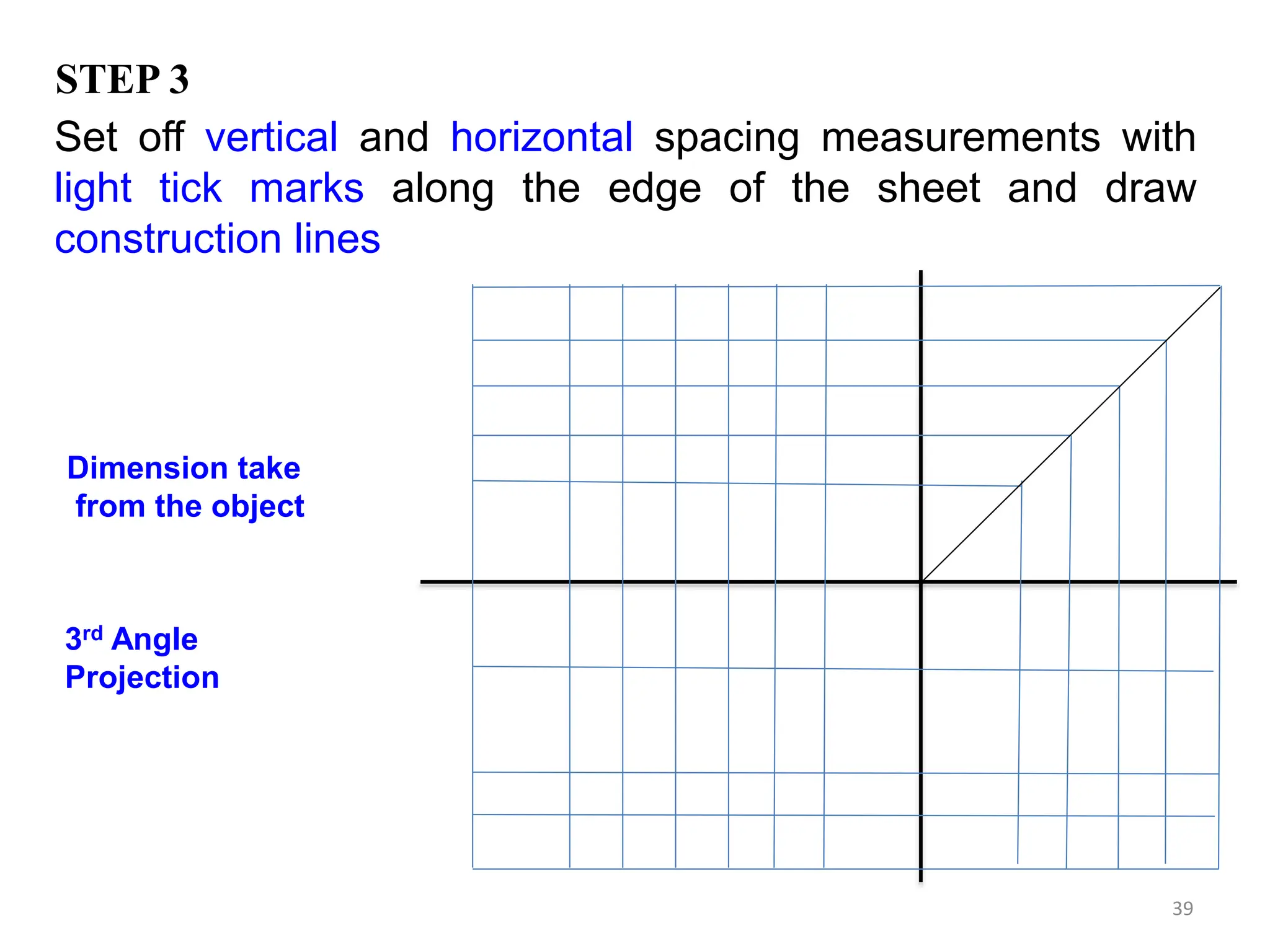
3. Advice is provided on laying out multi-view drawings on a sheet, including spacing of views and orientation of projection lines.
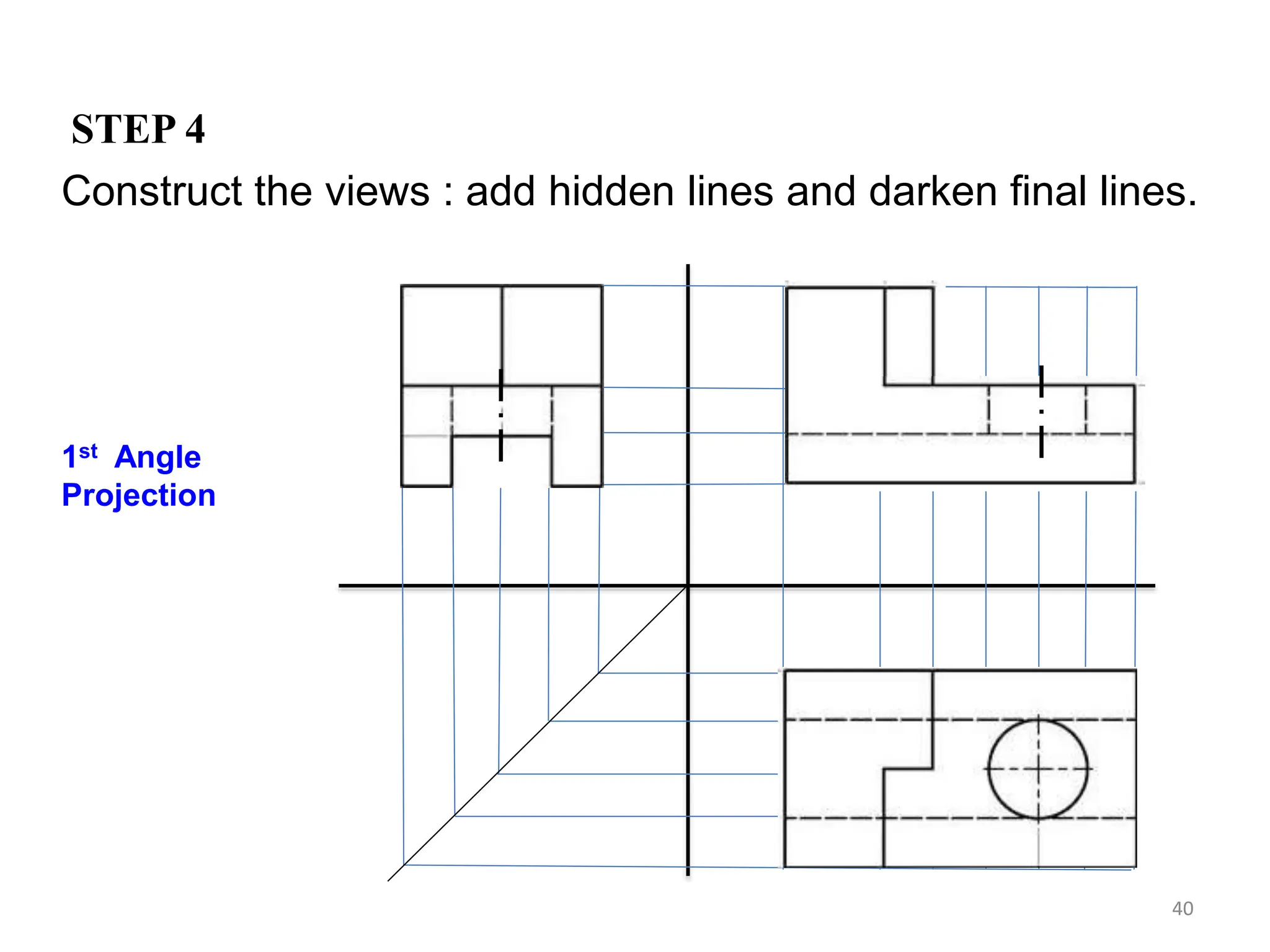
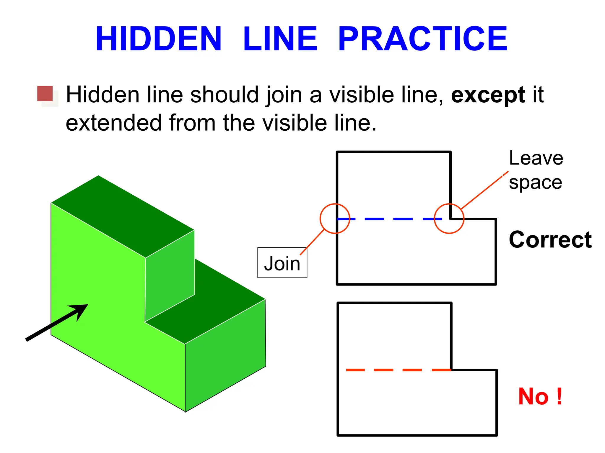
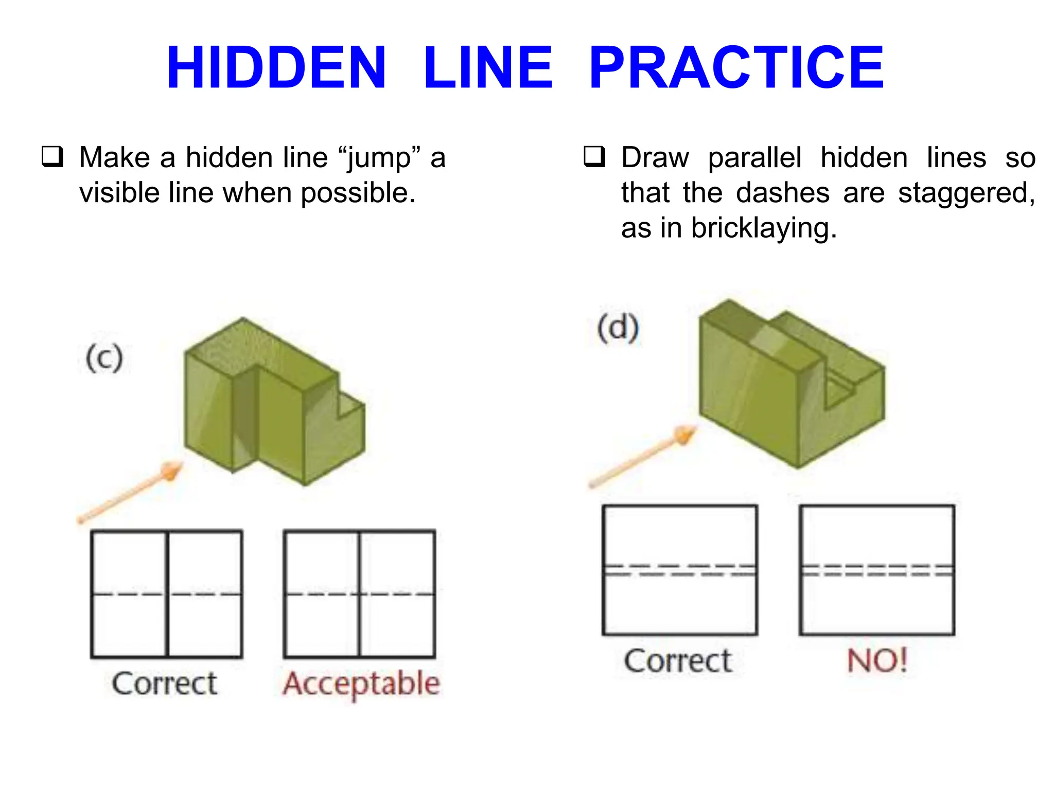
4. Key aspects of multi-view drawings like hidden lines, center lines, and projecting curved surfaces are covered. Examples of applying these concepts are also included.
![ADDIS ABABA SCIENCE AND
TECHNOLOGY
UNIVERSITY
Collage of Electrical and Mechanical
Engineering
Department of Mechanical Engineering
COURSE :ENGINEERING DRAWING [Meng1011]](https://image.slidesharecdn.com/chapter3-240208074754-84f608cc/75/CHAPTER-3-MULTI-VIEW-DRAWING-2-pptx-1-2048.jpg)