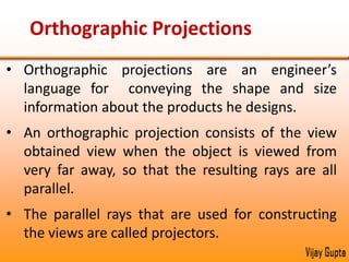
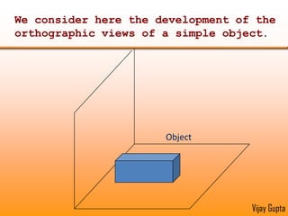
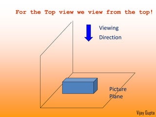
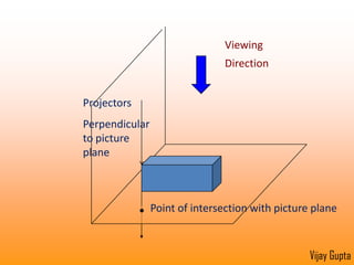
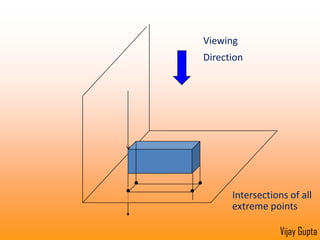
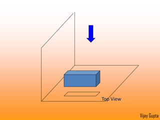
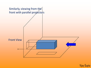
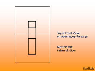
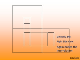
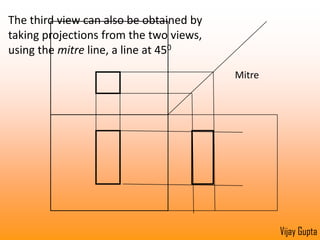
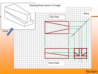
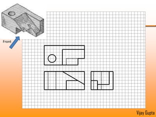
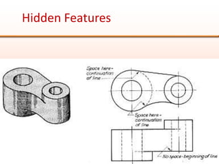
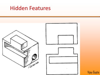
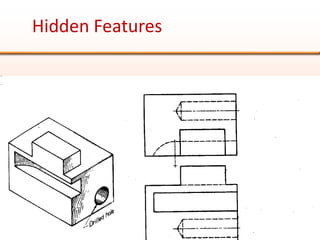
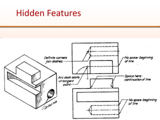
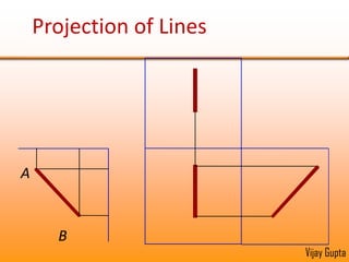
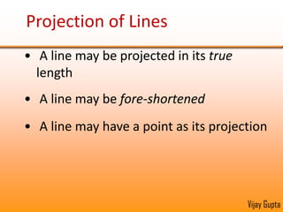
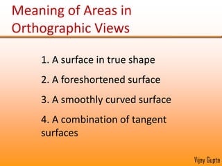
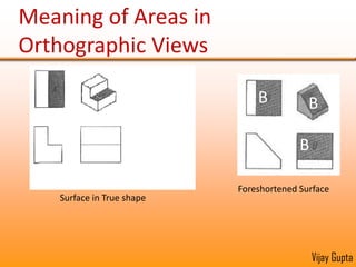
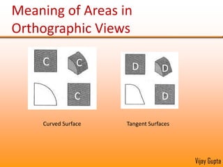
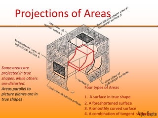
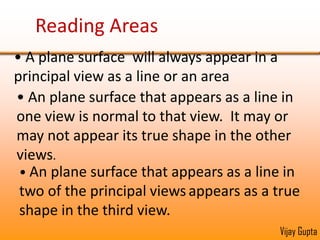
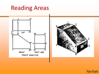
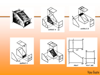
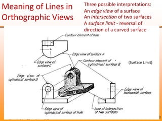
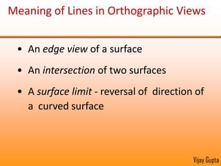
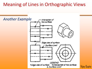
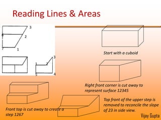
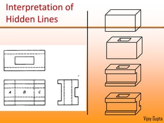
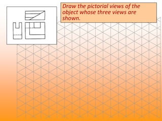
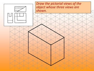
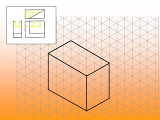
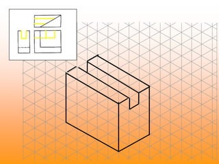
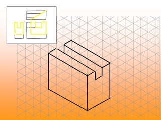
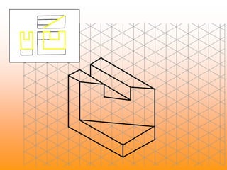
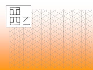
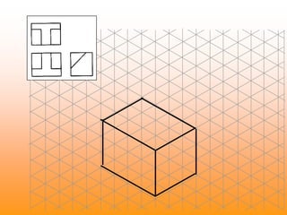
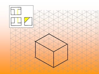
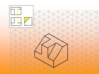
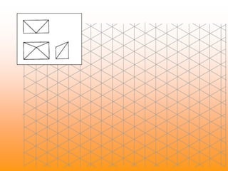
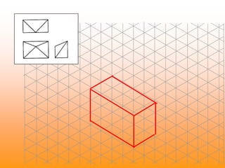
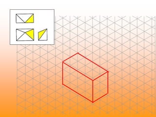
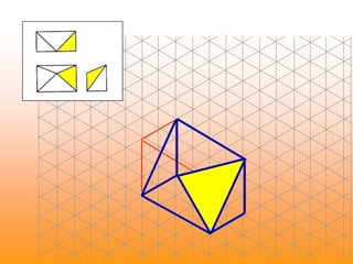
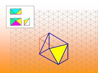
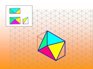
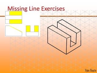
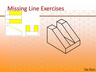
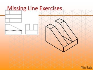
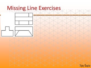
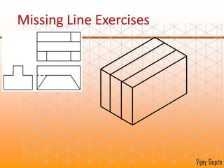
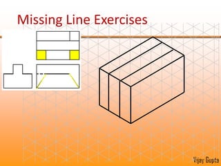
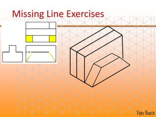
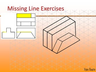
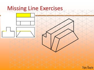
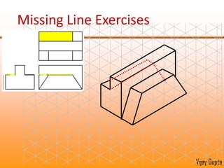
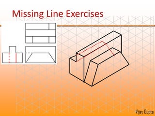
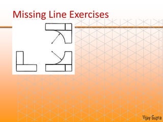
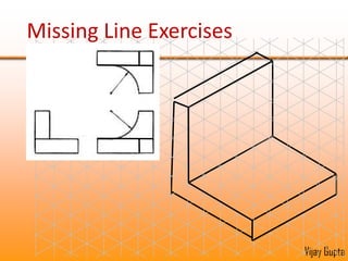
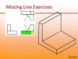
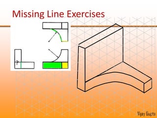
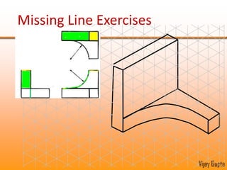
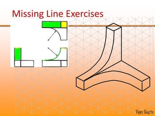
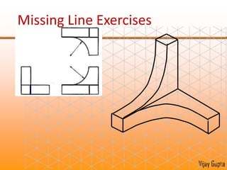
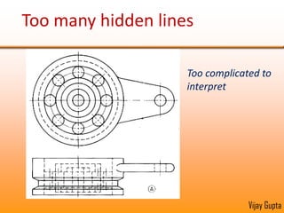
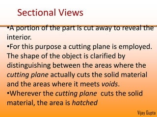
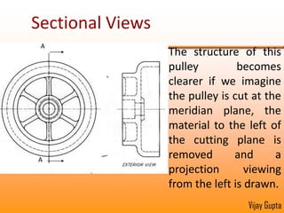
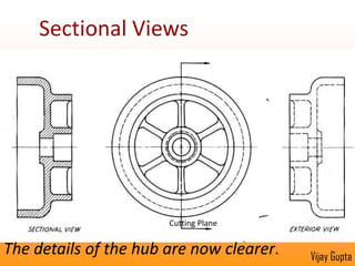
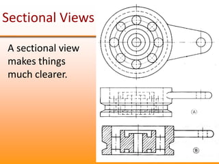
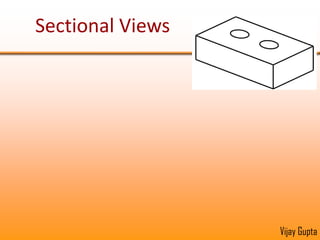
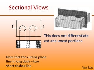
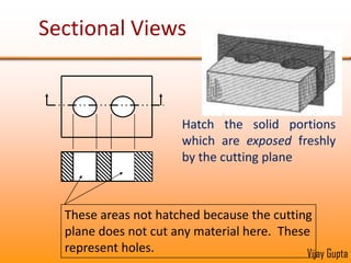
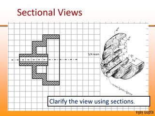
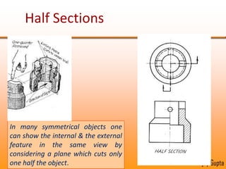
Orthographic projections are a method for conveying the shape and size of engineered objects using 2D drawings. They involve taking views of an object from the front, top, and side with parallel projecting rays. Lines and areas in the views represent edges, surfaces, and intersections between surfaces of the 3D object. Sectional views use a cutting plane to reveal internal features that would otherwise be hidden. They distinguish cut areas, which are hatched, from open areas cut through by the sectioning plane. Orthographic projections and sections effectively communicate 3D geometric information through 2D drawings.
This lecture contains the detail of isometric projections of an object. This will improve your skills to draw isometric views which is the major part of engineering drawings.
This is a guide on how to maximise your performance when answering Multiple Choice Questions (MCQ)
It has been created by a Business lecturer at College SA.
Tips For Constructing Objective Written Exam QuestionsSoha Rashed
Tips for constructing objective written exams (MCQs, Short answer questions, Modified essay questions, True/False and Matching questions) for assessing medical students.
It contains notes, examples, and exercises on multi-view drawing so fresh students can simply understand from this document. this document also briefly identifies the difference between first angle projection and third angle projection including examples.
Compare the differences and uniqueness between Isometric, Oblique, an.pdfFootageetoffe16
Compare the differences and uniqueness between Isometric, Oblique, and Perspective views.
Please explain why CAD becomes the most important and fundamental tool in modern design
and Manufacturing as well as in product development.
Solution
Isometric views
Oblique views
Perspective views
An isometric view represents an object in three dimensions with exact dimensional
representation.
Here the 3 sides of the object are drawn with all the vertical lines being vertically but all
horizontal lines at 30 degree to the base line (x-axis line)
All the three coordinate axes appear equally foreshortened and the angle between any two of
them is 120 degrees
In Isometric drawings, object are drawn with all its 3 planes parallel to projection planes and all
the lines/edges are parallel to its respective foreshortened axes (30 degree axis) and can also be
measured.
All the lines/edges are drawn to the full length scale rather than reducing them to the true
projection length.
Oblique view also represents an object in the 3D format.
But here the objects are drawn with the most distinguishing features facing directly towards the
observer, showing the true shape of these features. E.g. Circular features like round holes are
drawn on this front face as true circles.
Oblique view will always show the object as being perfectly flat with respect to the picture plane
(i.e., that particular face of the object will have only two dimensions from the viewer\'s point of
view).
Oblique view shows one face with distinguishing feature of the object in true shape, but the other
faces with foreshorten depth.
It is quite a simple technique compared to isometric or even perspective drawing as the only the
face with distinguishing feature has to be drawn to the scale.
Perspective views also represent an object in the 3D format with approximate representation.
The lines/edges of an object seem to meet at a point over a distance. This point is called the
vanishing point.
Here the vertical lines remain vertical, horizontal lines remain horizontal but the line that
represents the depth of the object (3rd Dimension lines) are drawn converging on to this
vanishing point.
The depth lines are to be drawn from the vanishing point to the sides of the drawing paper as
guide lines.
Objects in a perspective drawing all the lines/edges are subject to foreshortening. The size of the
object is drawn smaller as their distance from the observer increases. As their distance from the
observer decreases they are drawn larger.
Isometric views
Oblique views
Perspective views
An isometric view represents an object in three dimensions with exact dimensional
representation.
Here the 3 sides of the object are drawn with all the vertical lines being vertically but all
horizontal lines at 30 degree to the base line (x-axis line)
All the three coordinate axes appear equally foreshortened and the angle between any two of
them is 120 degrees
In Isometric drawings, object are drawn with all its 3 planes parallel.
Hadj Ounis's most notable work is his sculpture titled "Metamorphosis." This piece showcases Ounis's mastery of form and texture, as he seamlessly combines metal and wood to create a dynamic and visually striking composition. The juxtaposition of the two materials creates a sense of tension and harmony, inviting viewers to contemplate the relationship between nature and industry.
Fashionista Chic Couture Maze & Coloring Adventures is a coloring and activity book filled with many maze games and coloring activities designed to delight and engage young fashion enthusiasts. Each page offers a unique blend of fashion-themed mazes and stylish illustrations to color, inspiring creativity and problem-solving skills in children.
Explore the multifaceted world of Muntadher Saleh, an Iraqi polymath renowned for his expertise in visual art, writing, design, and pharmacy. This SlideShare delves into his innovative contributions across various disciplines, showcasing his unique ability to blend traditional themes with modern aesthetics. Learn about his impactful artworks, thought-provoking literary pieces, and his vision as a Neo-Pop artist dedicated to raising awareness about Iraq's cultural heritage. Discover why Muntadher Saleh is celebrated as "The Last Polymath" and how his multidisciplinary talents continue to inspire and influence.
This tutorial offers a step-by-step guide on how to effectively use Pinterest. It covers the basics such as account creation and navigation, as well as advanced techniques including creating eye-catching pins and optimizing your profile. The tutorial also explores collaboration and networking on the platform. With visual illustrations and clear instructions, this tutorial will equip you with the skills to navigate Pinterest confidently and achieve your goals.
2. Introduction to Orthographic Projections Introducing Orthographic Projections as the language of engineering designers
3.
4. An orthographic projection consists of the view obtained view when the object is viewed from very far away, so that the resulting rays are all parallel.
5. The parallel rays that are used for constructing the views are called projectors.Vijay Gupta
6.
7. The intersections of the projectors with the picture plane are the projections of the points from which the projectors emanate.
17. Mitre The third view can also be obtained by taking projections from the two views, using the mitre line, a line at 450 Vijay Gupta
18. Two types of projections commonly used: I & III angle I-Angle In third angle, picture planes in between the viewer & object In first angle, picture plane behind the object III-Angle Vijay Gupta
19. Opening up of the box with the various views in III angle Vijay Gupta
20. The relationship on plane paper of the various views in III angle III Angle Top View Front View Right View Left View Vijay Gupta
43. Meaning of Areas in Orthographic Views B B B Foreshortened Surface Surface in True shape
44. Meaning of Areas in Orthographic Views C C D D C D Curved Surface Tangent Surfaces
45. Projections of Areas Some areas are projected in true shapes, while others are distorted. Areas parallel to picture planes are in true shapes Four types of Areas 1.A surface in true shape 2. A foreshortened surface 3. A smoothly curved surface 4. A combination of tangent surfaces
46.
47. An plane surface that appears as a line in one view is normal to that view. It may or may not appear its true shape in the other views.
54. Meaning of Lines in Orthographic Views Three possible interpretations: An edge view of a surface An intersection of two surfaces A surface limit - reversal of direction of a curved surface (Surface Limit)
58. We next illustrate how to read the orthographic drawings. This is done by interpreting the three view to ‘draw’ the represented by those view.
59. Reading Lines & Areas Start with a cuboid 3 6 2 7 1 Right front corner is cut away to represent surface 12345 3 1 2 Top front of the upper step is removed to reconcile the slope of 23 in side view. 4 5 Front top is cut away to create a step 1267
77. Missing Line Exercises In the examples that follow, one or more lines may be missing in (only) one view. Try constructing a pictorial view to determine what line(s) are missing.
78. Missing Line Exercises One or more lines may be missing in (only) one view. Try constructing a pictorial view to determine what line(s) are missing.
100. Sectional Views Whenever a representation becomes confused due to too many essential hidden details that it is difficult to interpret, sectional views are employed
103. For this purpose a cutting plane is employed. The shape of the object is clarified by distinguishing between the areas where the cutting plane actually cuts the solid material and the areas where it meets voids.
108. Sectional Views This does not differentiate cut and uncut portions Note that the cutting plane line is long dash – two short dashes line
109. Sectional Views Hatch the solid portions which are exposed freshly by the cutting plane These areas not hatched because the cutting plane does not cut any material here. These represent holes.
114. Half Sections In many symmetrical objects one can show the internal & the external feature in the same view by considering a plane which cuts only one half the object.