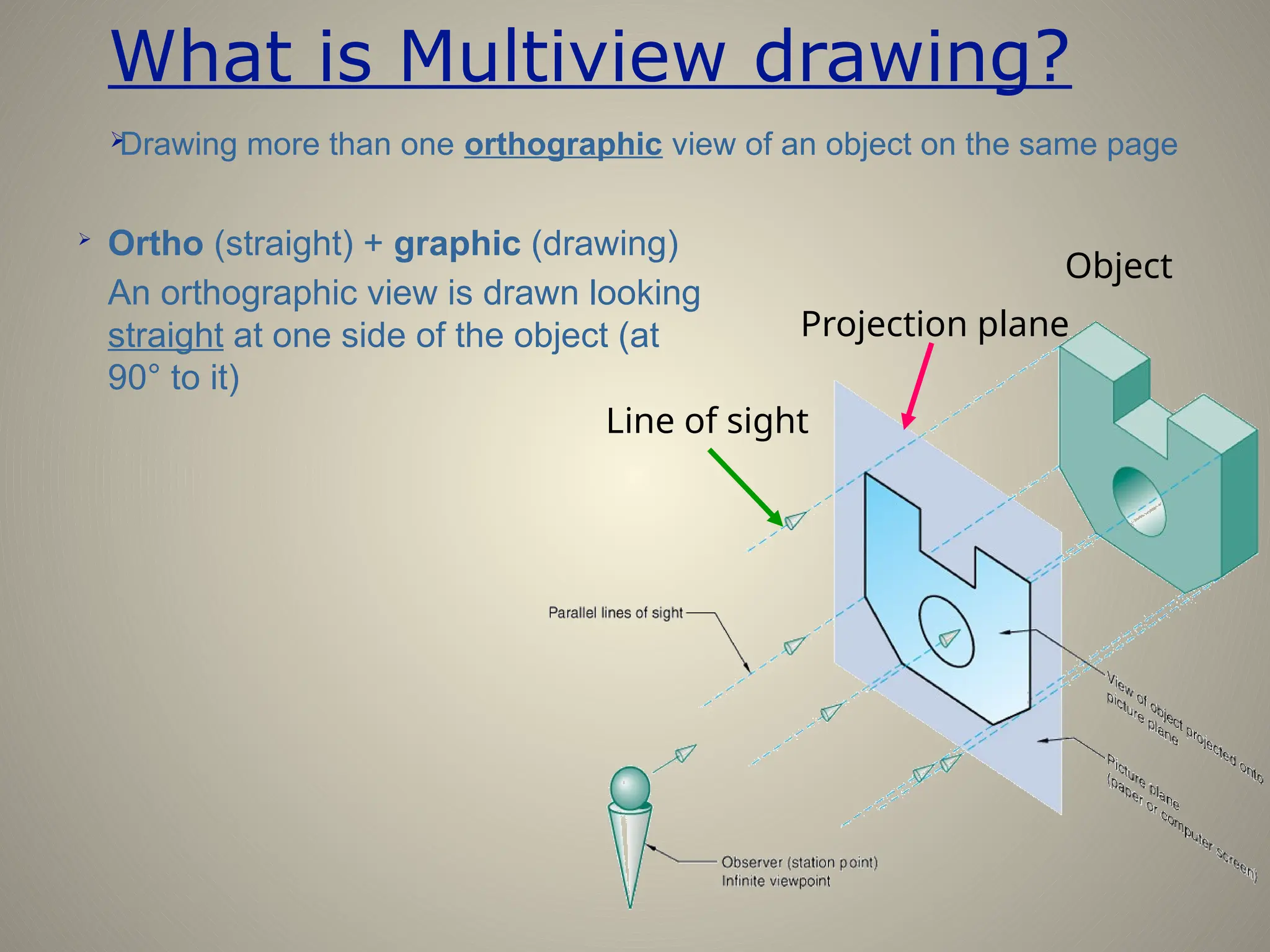
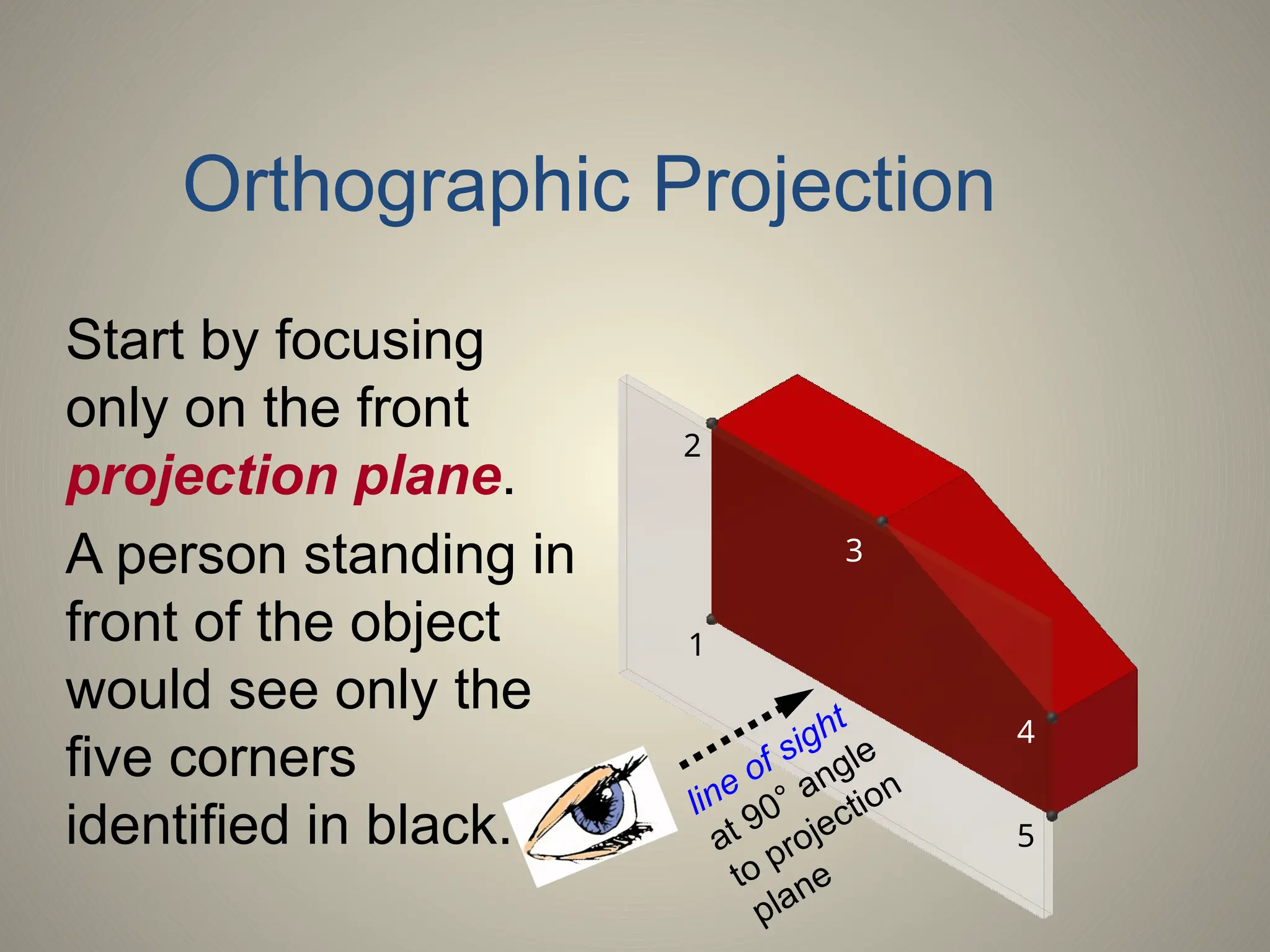
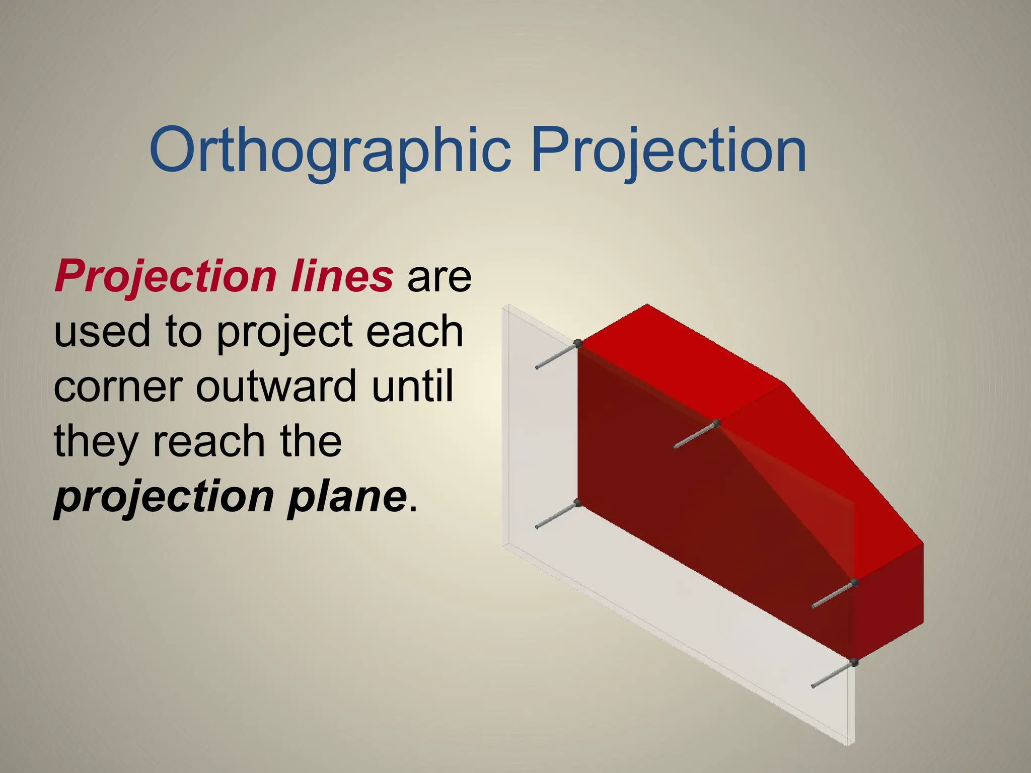
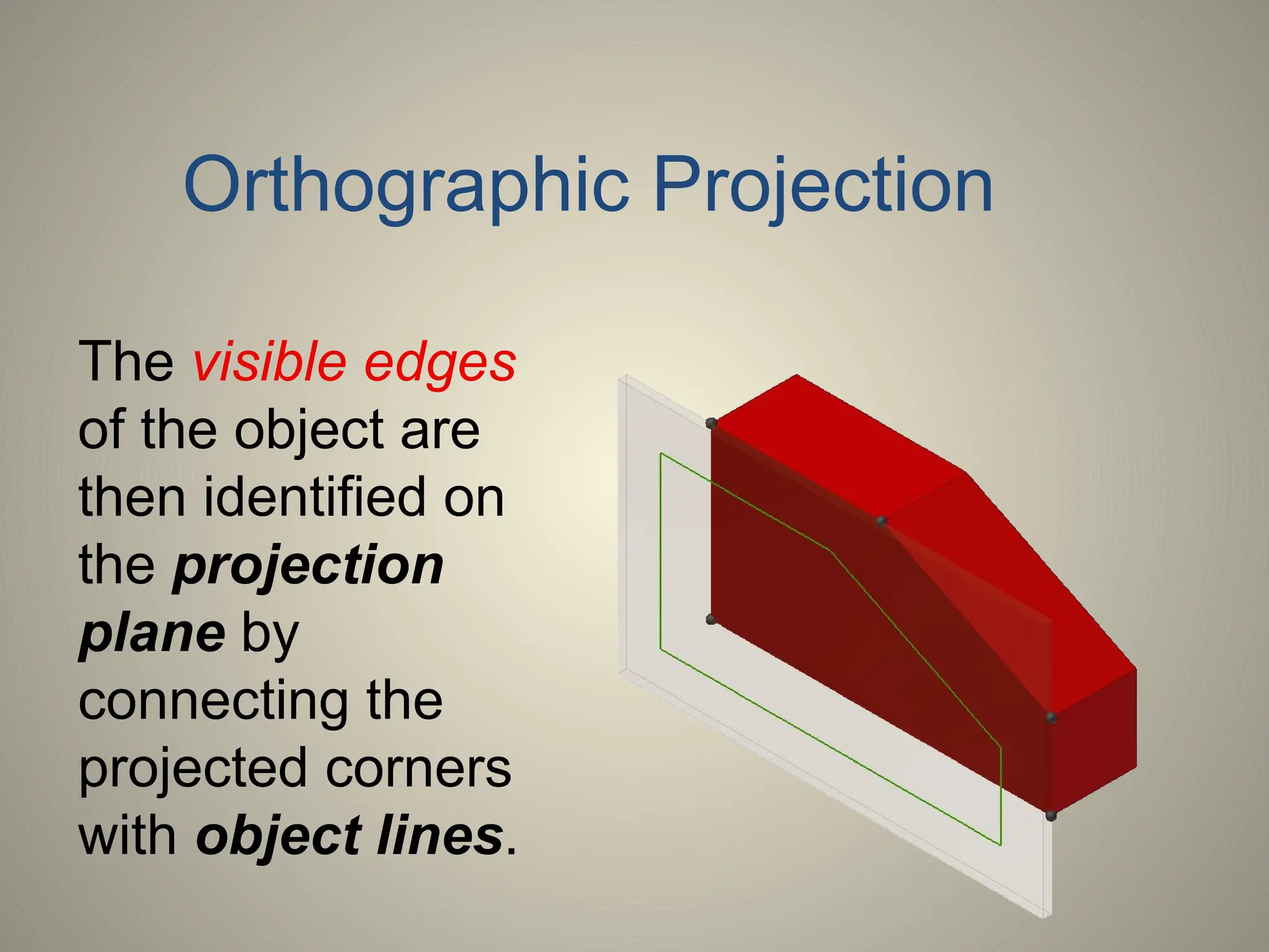
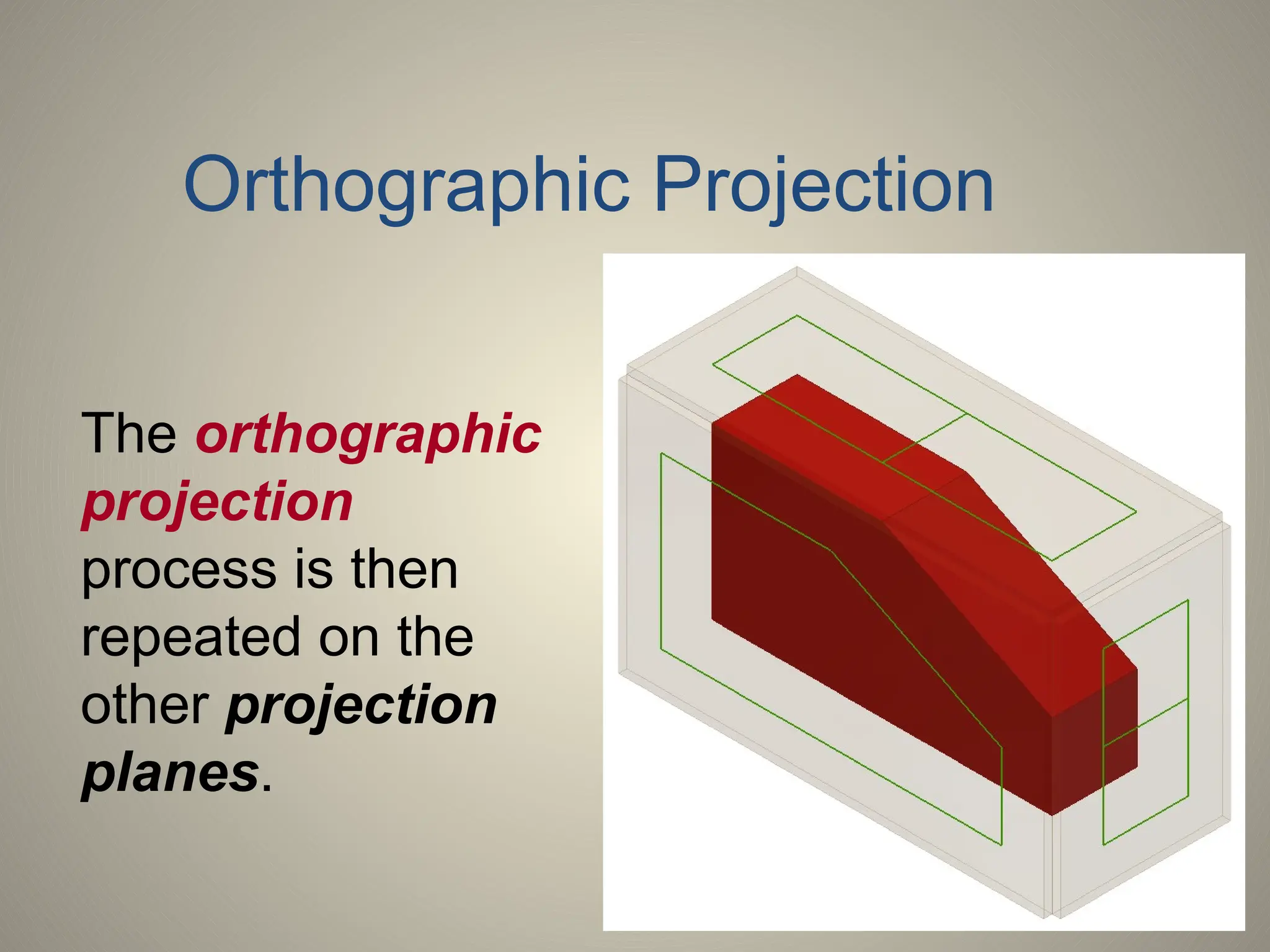
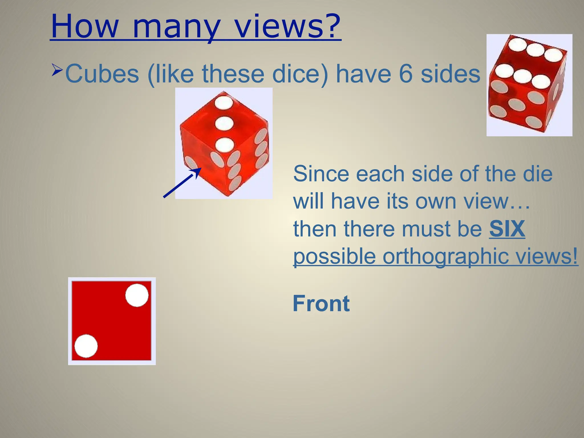
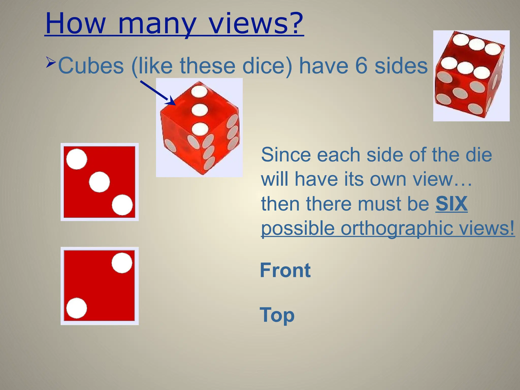
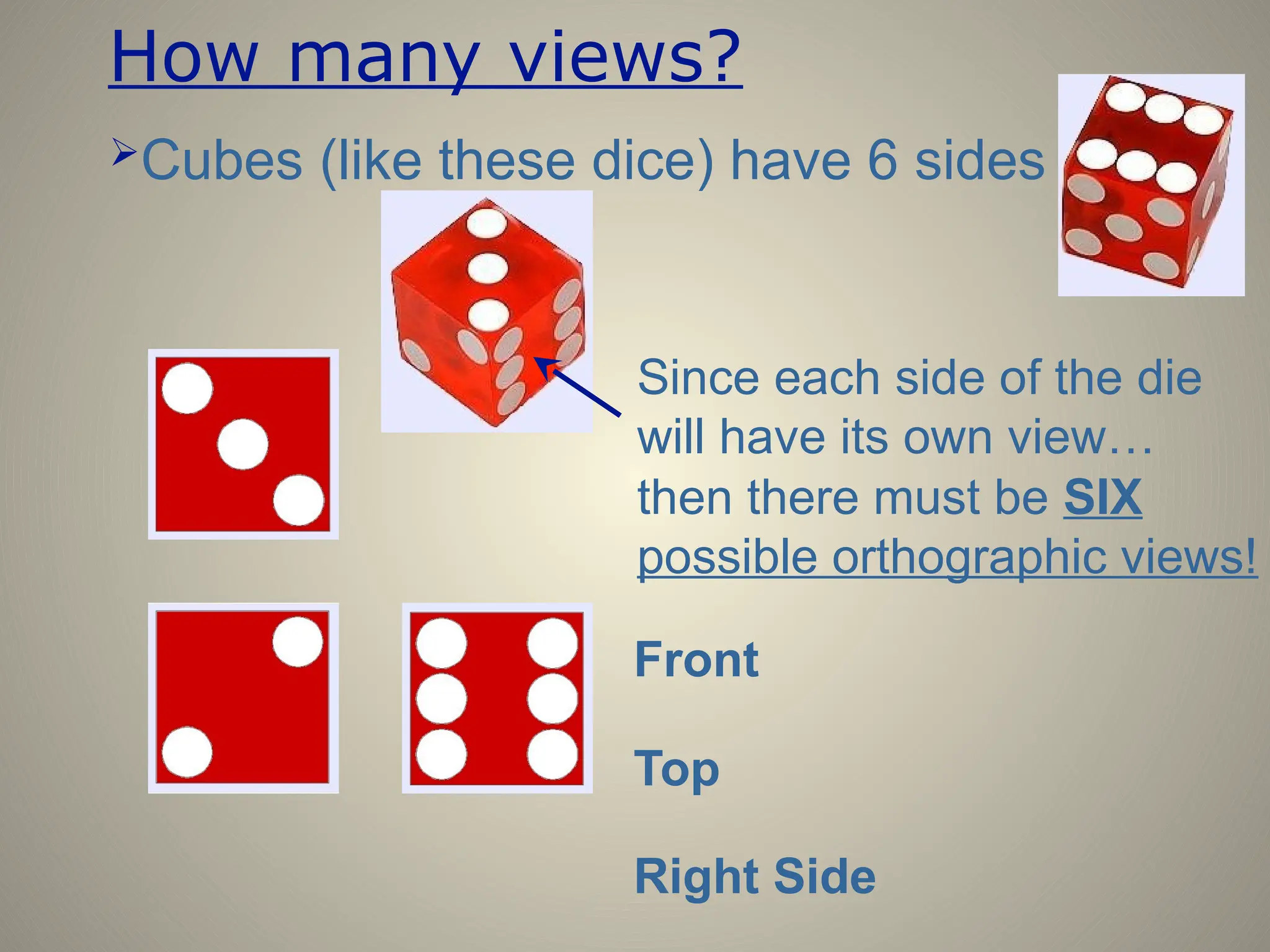
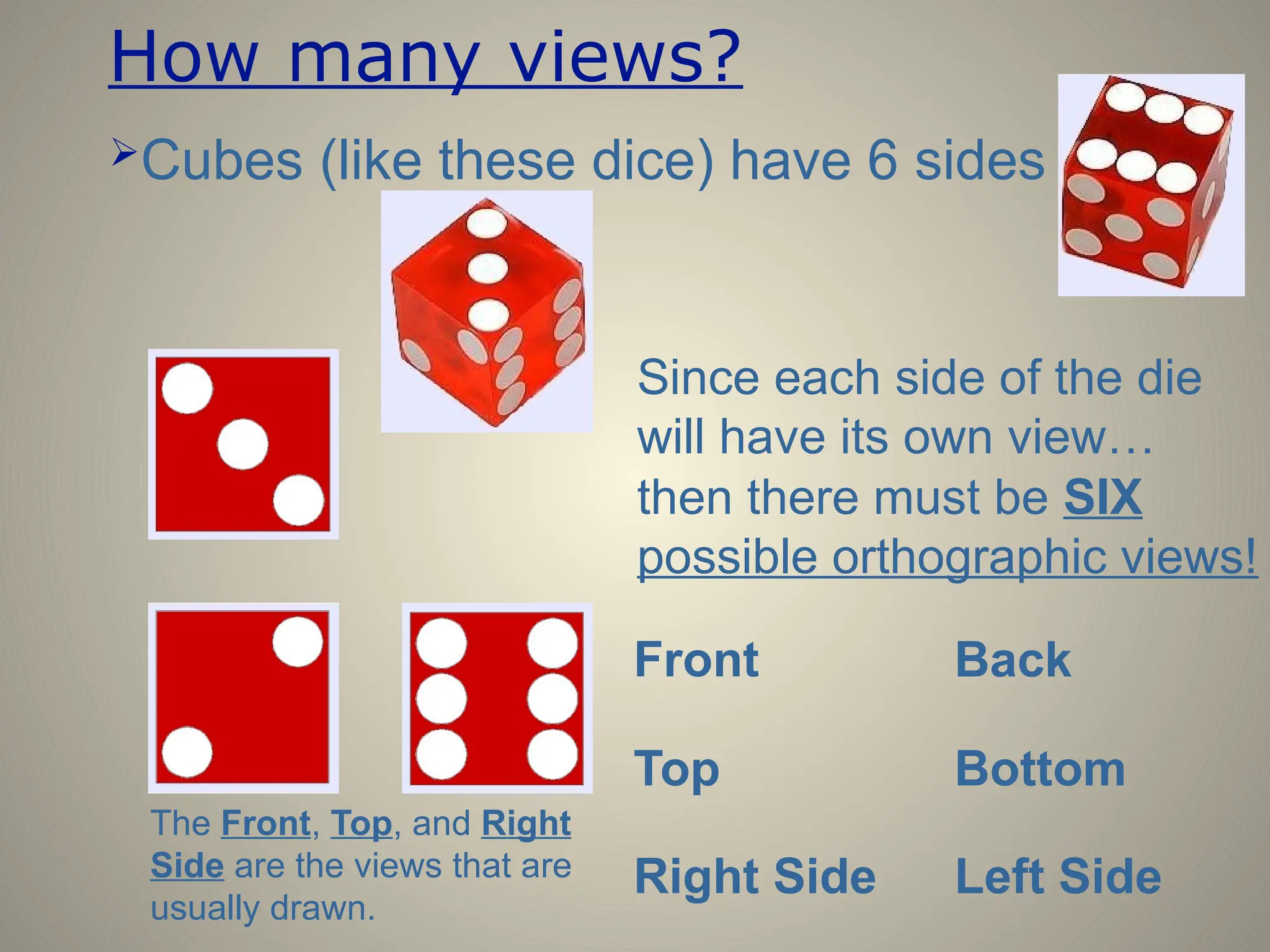
MECHANICAL DRAWING
Different views of an object
Objects may be drawn in different ways
Pictorial
Multiview
•Better for showing true size
and shape
•Each view only shows two
dimensions
•Better for visualizing the
object
•All three dimensions
shown on a single view
Multiview Drawing
Multiview Drawing
A multiview drawing is one that shows two
or more two-dimensional views of a three-
dimensional object.
Multiview drawings provide the shape
description of an object. When combined
with dimensions, multiview drawings serve
as the main form of communication
between designers and manufacturers.
Multiview Drawing
• Another name for orthographic projection is
multiview drawing
• Involves visualization and implementation
– Ability to see clearly in the mind’s eye an object
– Process of drawing the object
Angles of Projection
• First-angle projection
– Used by many European countries
– Object is projected onto planes
from the first angle or quadrant
• Front view projected to vertical plane
• Top view projected to horizontal plane
• Left-side view projected to profile
plane
TOP VIEW
FRONT VIEW RSIDE
Angles of Projection
• Third-angle projection
– Standard for the United States
– Third quadrant is used for
projection
• Front view projected to vertical
plane
• Top view projected to horizontal
plane
• Right-side view projected to
profile plane
1.63 1.25
5.13
2.00
2.88
2.25
1.50
2.50
3.50
45°
Ø1.52
TOP VIEW
FRONT VIEW R. SIDE
VIEW
Choosing Views
• Most commonly used
views
– Front View
– Top View
– Right Side View
• Most descriptive view is
typically designated as
the Front View
Choosing Views
• Complex objects require three views to
describe its shape
• Simple objects can be described with
two views
– Ex: Soda Can
• Thin objects can be described with
only one view
– Depth is given in a note
– Ex: Erasing Shield
1.63 1.25
5.13
2.00
2.88
1.75
1.50
2.00
3.00
Ø2.22
TOP VIEW
FRONT VIEW R. SIDE VIEW
45°
SPECIAL CAM R. MIGLIORATO 5/9/03 SCALE 1:1 16-52 12 NBHS
Placement of Views
• Views should be visually balanced
within the working space
Steps for Centering a Drawing
.75
.25
8.50
7.00
10.50
11.00
.50
.25 .25
• Draw border and title block using light construction lines
• Draw diagonal lines from corners of border
Layout of Views
Steps for Centering a Drawing
• Add:
– Length 5.13
– Space 1.50
– Width 2.00
– Horizontal 8.63
– Height 3.00
– Space 1.50
– Width 2.00
– Vertical 6.50
1.63 1.25
5.13
2.00
2.88
1.75
1.50
2.00
3.00
Ø2.22
TOP VIEW
FRONT VIEW
R. SIDE
VIEW
45°
4.3"
3"
4.3"
3"
Steps for Centering a Drawing
• Draw a box the size of all views
• Measure from the center:
– Half the width
– Half the height
FRONT VIEW
R. SIDE
VIEW
TOP VIEW
5.13 1.50 2.00
3.00
1.50
2.00
Steps for Centering a Drawing
• Draw in views using light construction lines
Adding Details
• Add holes and features
• Transfer horizontal and vertical features
• Use miter line to transfer depth
TOP VIEW
FRONT VIEW R. SIDE VIEW
SPECIAL CAM R. MIGLIORATO 5/9/03 SCALE 1:1 16-52 12 NBHS
Straight Edges
• Edges that are parallel to a plane of projection
appear as lines
• Edges that are inclined to a plane of projection
appear as foreshortened lines
POINT
VIEW
TRUE LENGTH
TRUE LENGTH
FORESHORTENED
FORESHORTENED
Curved Edges
• Curved edges project as straight lines on the plane
to which they are perpendicular
• Curved edges project as curved lines on the planes
to which they are parallel or inclined
Normal Surfaces
Normal surfaces appear as an edge in
two opposite principal views, and
appear a surface in all other principal
views.
Inclined Surfaces
• Inclined surfaces appear as an edge in two
opposite principal views, and appear
foreshortened (not true size) in all other
principal views.
Oblique Surfaces
• Oblique surfaces do not appear either as an
edge or true size in any principal view.
NO LINE
NO
LINE
Intersections & Tangencies
• Where a curved surface is tangent to a plane
surface, no line should be shown where they
join
Intersections & Tangencies
• Where a plane surface intersects a curved
surface, an edge is formed
LINE
LINE
What is Multiview drawing?

Ortho (straight) + graphic (drawing)
An orthographic view is drawn looking
straight at one side of the object (at
90° to it)

Drawing more than one orthographic view of an object on the same page
Line of sight
Projection plane
Object
Orthographic projection is a technique
that is used to create multiview drawings.
Orthographic projection is any projection
of the features of an object onto an
imaginary plane of projection. The
projection of the features of the object is
made by lines of sight that are
perpendicular to the plane of projection.
Orthographic Projection
The best way
to understand
orthographic
projection is
to imagine an
object
contained
inside a glass
box.
Orthographic Projection
There is a total of
six glass walls
surrounding the
object. Each wall
represents a
projection plane
onto which a two-
dimensional object
view will be created.
Orthographic Projection
A projection plane, also referred to as a
plane of projection or picture plane, is an
imaginary surface that exists between the
viewer and the object.
The projection plane is the surface onto
which a two-dimensional view of a three-
dimensional object is projected and
created.
Projection Plane
Start by focusing
only on the front
projection plane.
A person standing in
front of the object
would see only the
five corners
identified in black.
1
2
3
4
5
line of sight
at 90° angle
to projection
plane
Orthographic Projection
Projection lines are
used to project each
corner outward until
they reach the
projection plane.
Orthographic Projection
A projection line is an imaginary line that
is used to locate or project the corners,
edges, and features of a three-dimensional
object onto an imaginary two-dimensional
surface.
Projection Lines
The visible edges
of the object are
then identified on
the projection
plane by
connecting the
projected corners
with object lines.
Orthographic Projection
The orthographic
projection
process is then
repeated on the
other projection
planes.
Orthographic Projection
A Question…
Each of the
blocks to the
right have the
same overall
dimensions
and colors.
What else to
they have in
common?
Answer ….
They all have
identical top
views!
HIDDEN LINES
MUTLIVIEW DRAWINGS
We place hidden lines
in a drawing to do the
following things:
1. Show hidden features
2. Clarify the position
and shape of features
3. Make the “plate” more
readable
(NOTE: The term
“plate” refers to a
finished drawing.)
How many views?
Cubes (like these dice) have 6 sides
Since each side of the die
will have its own view…
then there must be SIX
possible orthographic views!
Front
How many views?
Cubes (like these dice) have 6 sides
Since each side of the die
will have its own view…
then there must be SIX
possible orthographic views!
Front
Top
How many views?
Cubes (like these dice) have 6 sides
Since each side of the die
will have its own view…
then there must be SIX
possible orthographic views!
Front
Top
Right Side
How many views?
Cubes (like these dice) have 6 sides
Since each side of the die
will have its own view…
The Front, Top, and Right
Side are the views that are
usually drawn.
then there must be SIX
possible orthographic views!
Front
Top
Right Side
Back
Bottom
Left Side
Where do the views go?
All the views MUST be arranged correctly
Imagine “unfolding” the cube
to get proper view alignment.
The back view can be placed
in any of these four locations.
How does this work on other objects?
Place the object in a glass box
Top view goes above
Then “unfold” the box
R.Side view goes to the right
Front view is always central
What about details you can’t see?

Hidden lines show details that are not seen in all views
Draw hidden lines (dashed)
to show the detail
Project from hidden detail to
the other views
ANIMATED EXAMPLES
http://dossin.weebly.com/3-multi--
view-orthographic-projection-drawing.html
Multiview Drawing REVIEW

An orthographic view is drawn looking straight at one side of the object (at 90° to
it)
There are 6 possible orthographic
views: Front, Back, Top, Bottom,
Left Side, Right Side
The Front, Top, and R.Side views
are usually all that are drawn
Hidden lines show details you
can’t see in all views
Centering a Multiview Drawing Review
Make a sketch of the views needed for the drawing.
The space between the views is 1 ½”
What are the measurements needed to center the drawing?
What is the overall size of the box for the views?
Centering a Multiview Drawing Review
1.75
1.5
1.5
6.50
3.50
3.50
11.50
6.75
Layout of the 6 Views
Sketch the layout of the 6 views of this object and label the views.
TOP
FRONT
REAR L. SIDE
BOTTOM
R. SIDE

Lecture on multiview drawings in civil engineering drawing and its basics also about the projectins

  • 1.
  • 2.
    Different views ofan object Objects may be drawn in different ways Pictorial Multiview •Better for showing true size and shape •Each view only shows two dimensions •Better for visualizing the object •All three dimensions shown on a single view
  • 3.
  • 4.
    Multiview Drawing A multiviewdrawing is one that shows two or more two-dimensional views of a three- dimensional object. Multiview drawings provide the shape description of an object. When combined with dimensions, multiview drawings serve as the main form of communication between designers and manufacturers.
  • 5.
    Multiview Drawing • Anothername for orthographic projection is multiview drawing • Involves visualization and implementation – Ability to see clearly in the mind’s eye an object – Process of drawing the object
  • 6.
    Angles of Projection •First-angle projection – Used by many European countries – Object is projected onto planes from the first angle or quadrant • Front view projected to vertical plane • Top view projected to horizontal plane • Left-side view projected to profile plane
  • 7.
    TOP VIEW FRONT VIEWRSIDE Angles of Projection • Third-angle projection – Standard for the United States – Third quadrant is used for projection • Front view projected to vertical plane • Top view projected to horizontal plane • Right-side view projected to profile plane
  • 8.
    1.63 1.25 5.13 2.00 2.88 2.25 1.50 2.50 3.50 45° Ø1.52 TOP VIEW FRONTVIEW R. SIDE VIEW Choosing Views • Most commonly used views – Front View – Top View – Right Side View • Most descriptive view is typically designated as the Front View
  • 9.
    Choosing Views • Complexobjects require three views to describe its shape • Simple objects can be described with two views – Ex: Soda Can • Thin objects can be described with only one view – Depth is given in a note – Ex: Erasing Shield
  • 10.
    1.63 1.25 5.13 2.00 2.88 1.75 1.50 2.00 3.00 Ø2.22 TOP VIEW FRONTVIEW R. SIDE VIEW 45° SPECIAL CAM R. MIGLIORATO 5/9/03 SCALE 1:1 16-52 12 NBHS Placement of Views • Views should be visually balanced within the working space
  • 11.
    Steps for Centeringa Drawing .75 .25 8.50 7.00 10.50 11.00 .50 .25 .25 • Draw border and title block using light construction lines • Draw diagonal lines from corners of border
  • 12.
  • 13.
    Steps for Centeringa Drawing • Add: – Length 5.13 – Space 1.50 – Width 2.00 – Horizontal 8.63 – Height 3.00 – Space 1.50 – Width 2.00 – Vertical 6.50 1.63 1.25 5.13 2.00 2.88 1.75 1.50 2.00 3.00 Ø2.22 TOP VIEW FRONT VIEW R. SIDE VIEW 45°
  • 14.
    4.3" 3" 4.3" 3" Steps for Centeringa Drawing • Draw a box the size of all views • Measure from the center: – Half the width – Half the height
  • 15.
    FRONT VIEW R. SIDE VIEW TOPVIEW 5.13 1.50 2.00 3.00 1.50 2.00 Steps for Centering a Drawing • Draw in views using light construction lines
  • 16.
    Adding Details • Addholes and features • Transfer horizontal and vertical features • Use miter line to transfer depth TOP VIEW FRONT VIEW R. SIDE VIEW SPECIAL CAM R. MIGLIORATO 5/9/03 SCALE 1:1 16-52 12 NBHS
  • 17.
    Straight Edges • Edgesthat are parallel to a plane of projection appear as lines • Edges that are inclined to a plane of projection appear as foreshortened lines POINT VIEW TRUE LENGTH TRUE LENGTH FORESHORTENED FORESHORTENED
  • 18.
    Curved Edges • Curvededges project as straight lines on the plane to which they are perpendicular • Curved edges project as curved lines on the planes to which they are parallel or inclined
  • 19.
    Normal Surfaces Normal surfacesappear as an edge in two opposite principal views, and appear a surface in all other principal views.
  • 20.
    Inclined Surfaces • Inclinedsurfaces appear as an edge in two opposite principal views, and appear foreshortened (not true size) in all other principal views.
  • 21.
    Oblique Surfaces • Obliquesurfaces do not appear either as an edge or true size in any principal view.
  • 22.
    NO LINE NO LINE Intersections &Tangencies • Where a curved surface is tangent to a plane surface, no line should be shown where they join
  • 23.
    Intersections & Tangencies •Where a plane surface intersects a curved surface, an edge is formed LINE LINE
  • 24.
    What is Multiviewdrawing?  Ortho (straight) + graphic (drawing) An orthographic view is drawn looking straight at one side of the object (at 90° to it)  Drawing more than one orthographic view of an object on the same page Line of sight Projection plane Object
  • 25.
    Orthographic projection isa technique that is used to create multiview drawings. Orthographic projection is any projection of the features of an object onto an imaginary plane of projection. The projection of the features of the object is made by lines of sight that are perpendicular to the plane of projection. Orthographic Projection
  • 26.
    The best way tounderstand orthographic projection is to imagine an object contained inside a glass box. Orthographic Projection
  • 27.
    There is atotal of six glass walls surrounding the object. Each wall represents a projection plane onto which a two- dimensional object view will be created. Orthographic Projection
  • 28.
    A projection plane,also referred to as a plane of projection or picture plane, is an imaginary surface that exists between the viewer and the object. The projection plane is the surface onto which a two-dimensional view of a three- dimensional object is projected and created. Projection Plane
  • 29.
    Start by focusing onlyon the front projection plane. A person standing in front of the object would see only the five corners identified in black. 1 2 3 4 5 line of sight at 90° angle to projection plane Orthographic Projection
  • 30.
    Projection lines are usedto project each corner outward until they reach the projection plane. Orthographic Projection
  • 31.
    A projection lineis an imaginary line that is used to locate or project the corners, edges, and features of a three-dimensional object onto an imaginary two-dimensional surface. Projection Lines
  • 32.
    The visible edges ofthe object are then identified on the projection plane by connecting the projected corners with object lines. Orthographic Projection
  • 33.
    The orthographic projection process isthen repeated on the other projection planes. Orthographic Projection
  • 34.
    A Question… Each ofthe blocks to the right have the same overall dimensions and colors. What else to they have in common?
  • 35.
    Answer …. They allhave identical top views!
  • 36.
    HIDDEN LINES MUTLIVIEW DRAWINGS Weplace hidden lines in a drawing to do the following things: 1. Show hidden features 2. Clarify the position and shape of features 3. Make the “plate” more readable (NOTE: The term “plate” refers to a finished drawing.)
  • 37.
    How many views? Cubes(like these dice) have 6 sides Since each side of the die will have its own view… then there must be SIX possible orthographic views! Front
  • 38.
    How many views? Cubes(like these dice) have 6 sides Since each side of the die will have its own view… then there must be SIX possible orthographic views! Front Top
  • 39.
    How many views? Cubes(like these dice) have 6 sides Since each side of the die will have its own view… then there must be SIX possible orthographic views! Front Top Right Side
  • 40.
    How many views? Cubes(like these dice) have 6 sides Since each side of the die will have its own view… The Front, Top, and Right Side are the views that are usually drawn. then there must be SIX possible orthographic views! Front Top Right Side Back Bottom Left Side
  • 41.
    Where do theviews go? All the views MUST be arranged correctly Imagine “unfolding” the cube to get proper view alignment. The back view can be placed in any of these four locations.
  • 42.
    How does thiswork on other objects? Place the object in a glass box Top view goes above Then “unfold” the box R.Side view goes to the right Front view is always central
  • 43.
    What about detailsyou can’t see?  Hidden lines show details that are not seen in all views Draw hidden lines (dashed) to show the detail Project from hidden detail to the other views
  • 44.
  • 45.
    Multiview Drawing REVIEW  Anorthographic view is drawn looking straight at one side of the object (at 90° to it) There are 6 possible orthographic views: Front, Back, Top, Bottom, Left Side, Right Side The Front, Top, and R.Side views are usually all that are drawn Hidden lines show details you can’t see in all views
  • 46.
    Centering a MultiviewDrawing Review Make a sketch of the views needed for the drawing. The space between the views is 1 ½” What are the measurements needed to center the drawing? What is the overall size of the box for the views?
  • 47.
    Centering a MultiviewDrawing Review 1.75 1.5 1.5 6.50 3.50 3.50 11.50 6.75
  • 48.
    Layout of the6 Views Sketch the layout of the 6 views of this object and label the views. TOP FRONT REAR L. SIDE BOTTOM R. SIDE