Downloaded 392 times

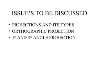
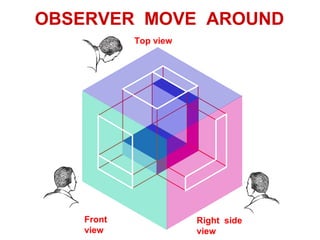
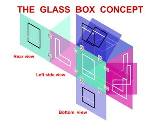
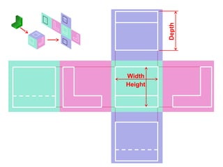
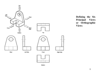
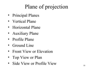
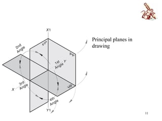
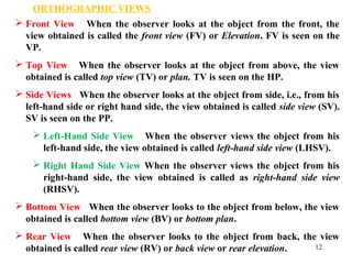
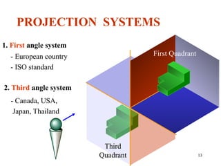
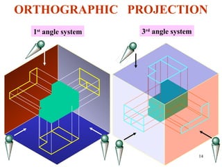
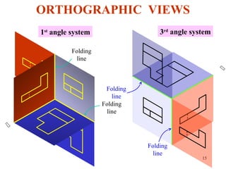
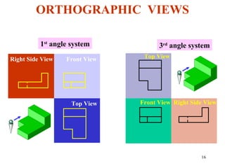
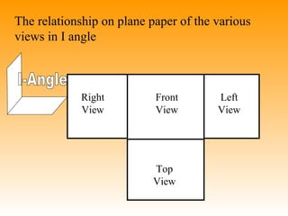
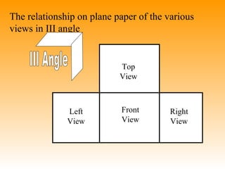
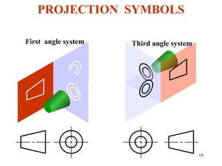
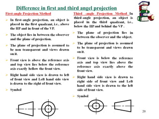
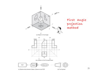
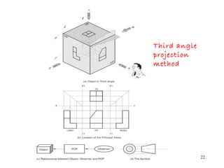
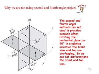

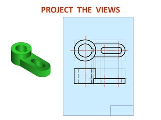
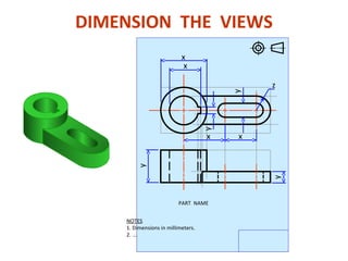
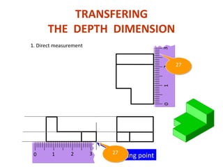
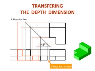
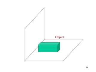
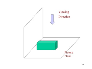
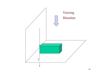
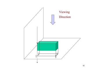
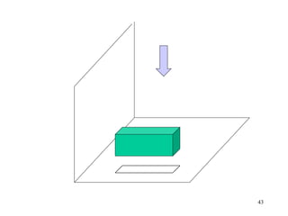
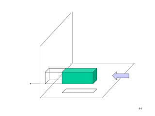
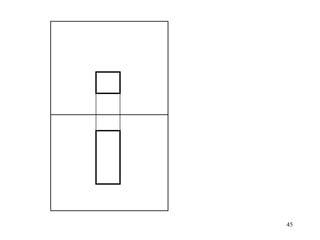
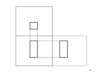
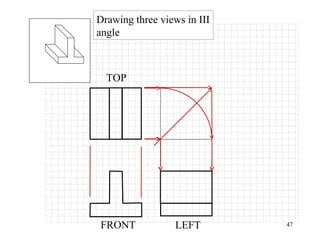
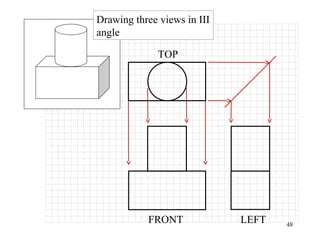
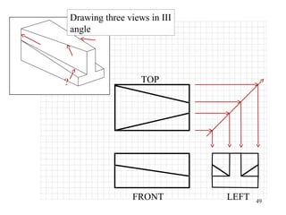
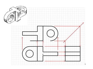
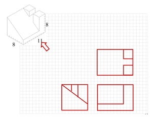
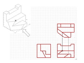

This document discusses orthographic projection and its types. It explains that orthographic projection involves obtaining views of an object by using parallel projectors that are perpendicular to the plane of projection. The key views obtained are the front, top, and side views. It also discusses the differences between first angle and third angle projection systems, with third angle being the more commonly used ISO standard.