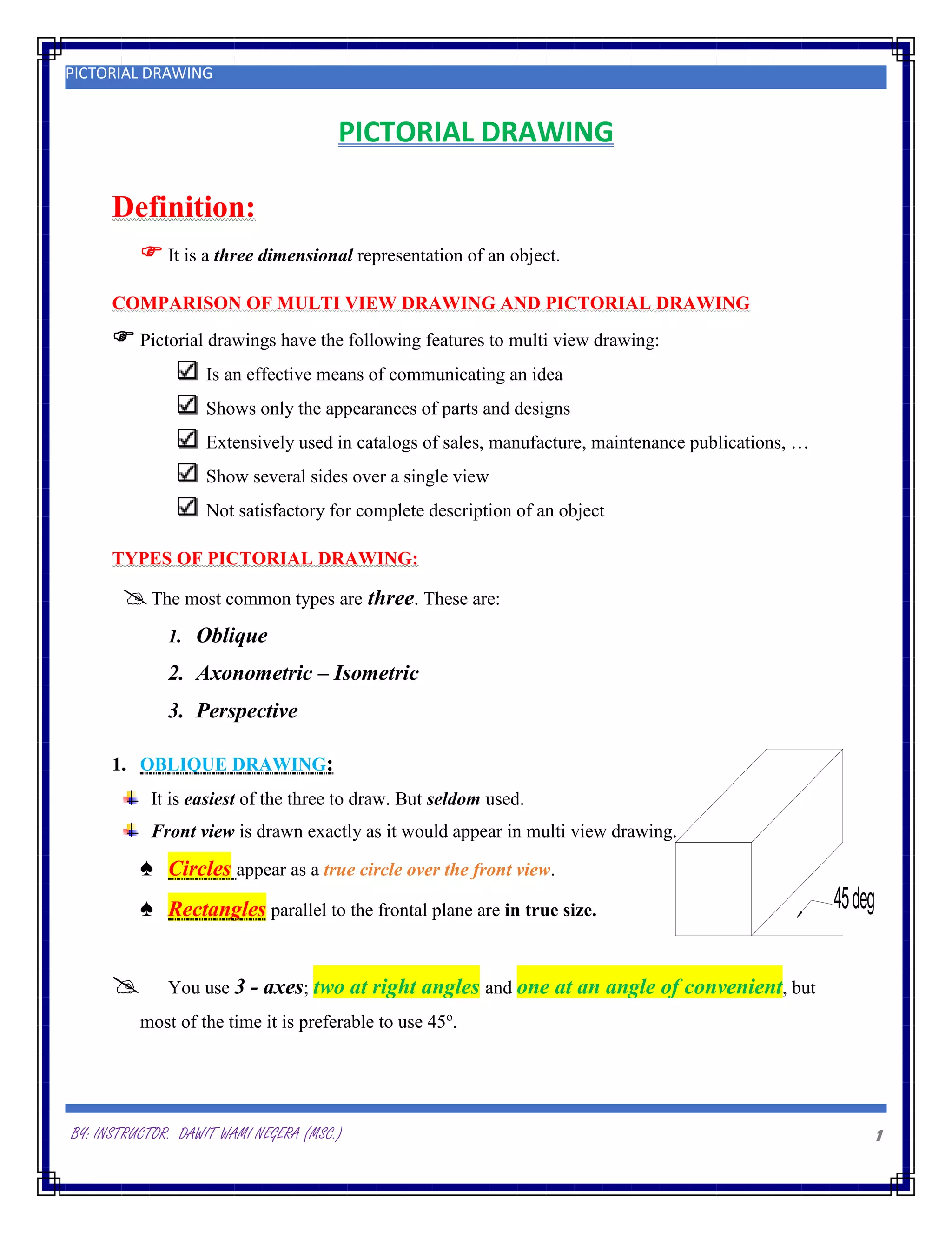
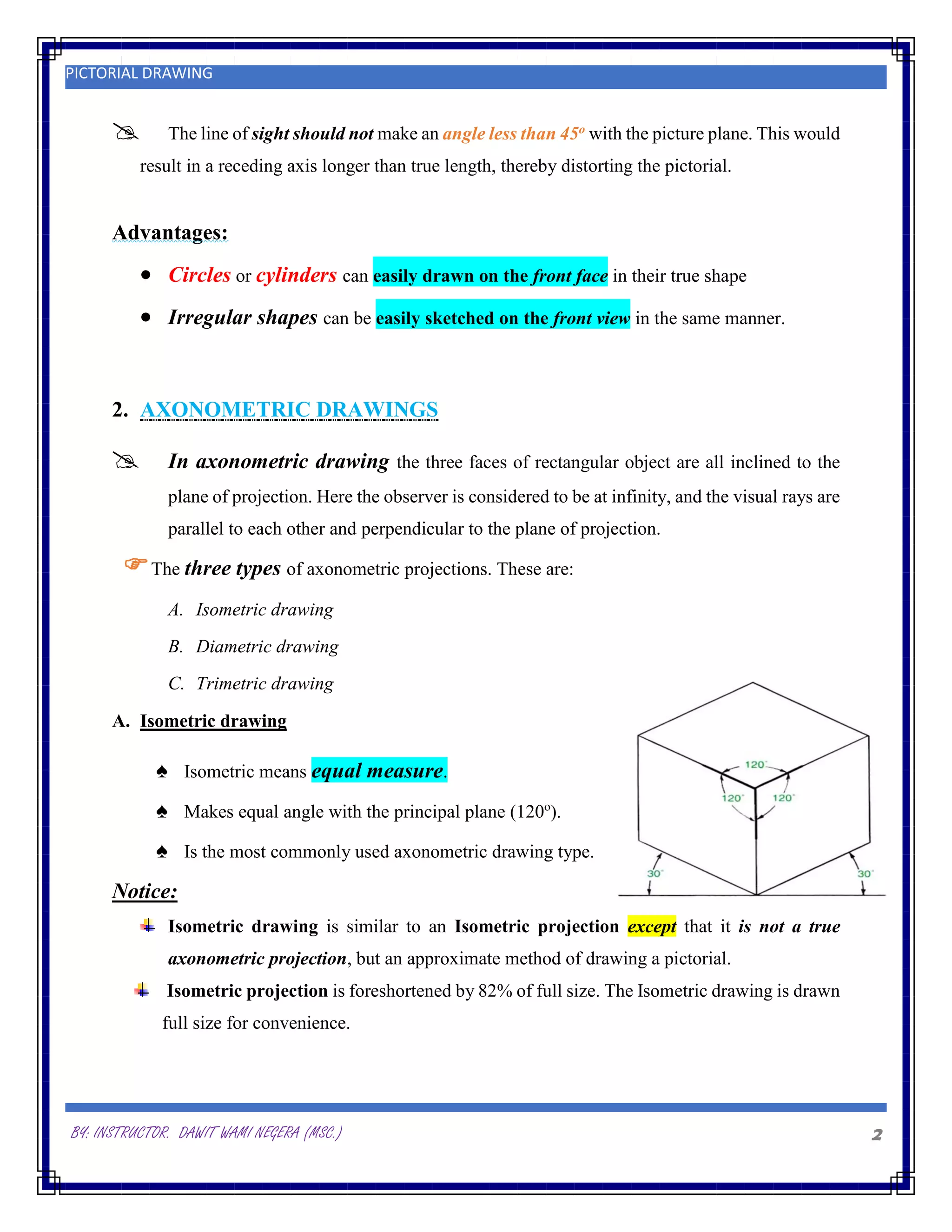
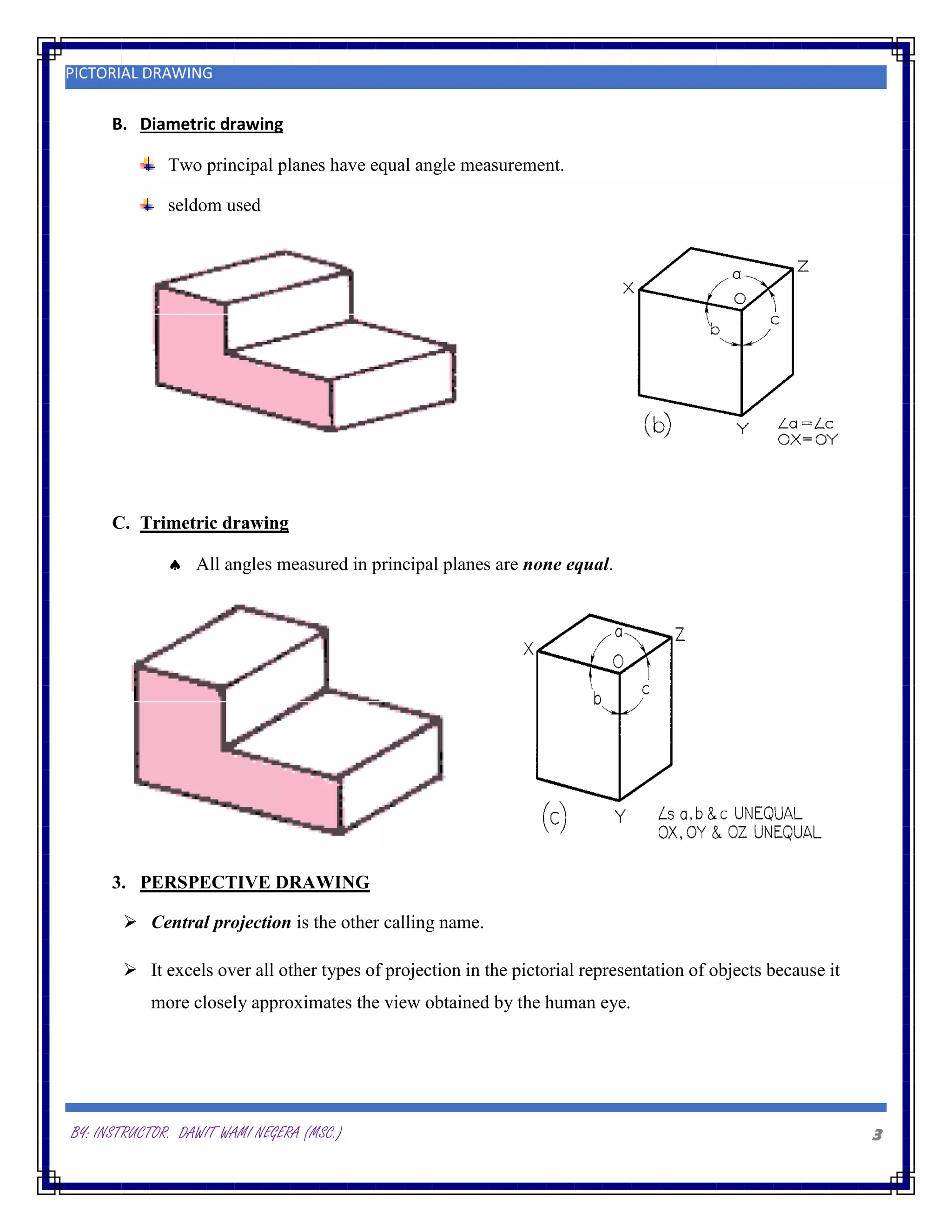
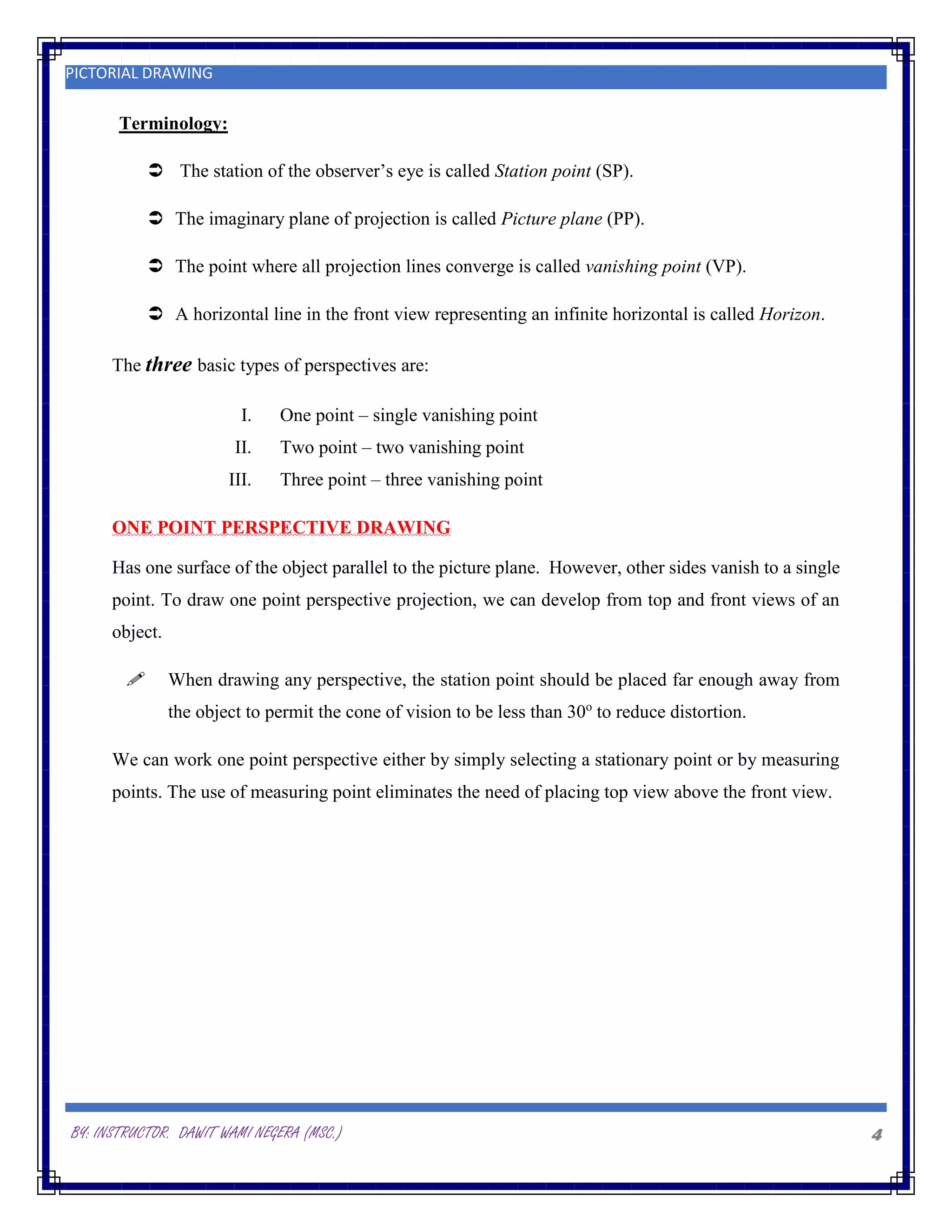
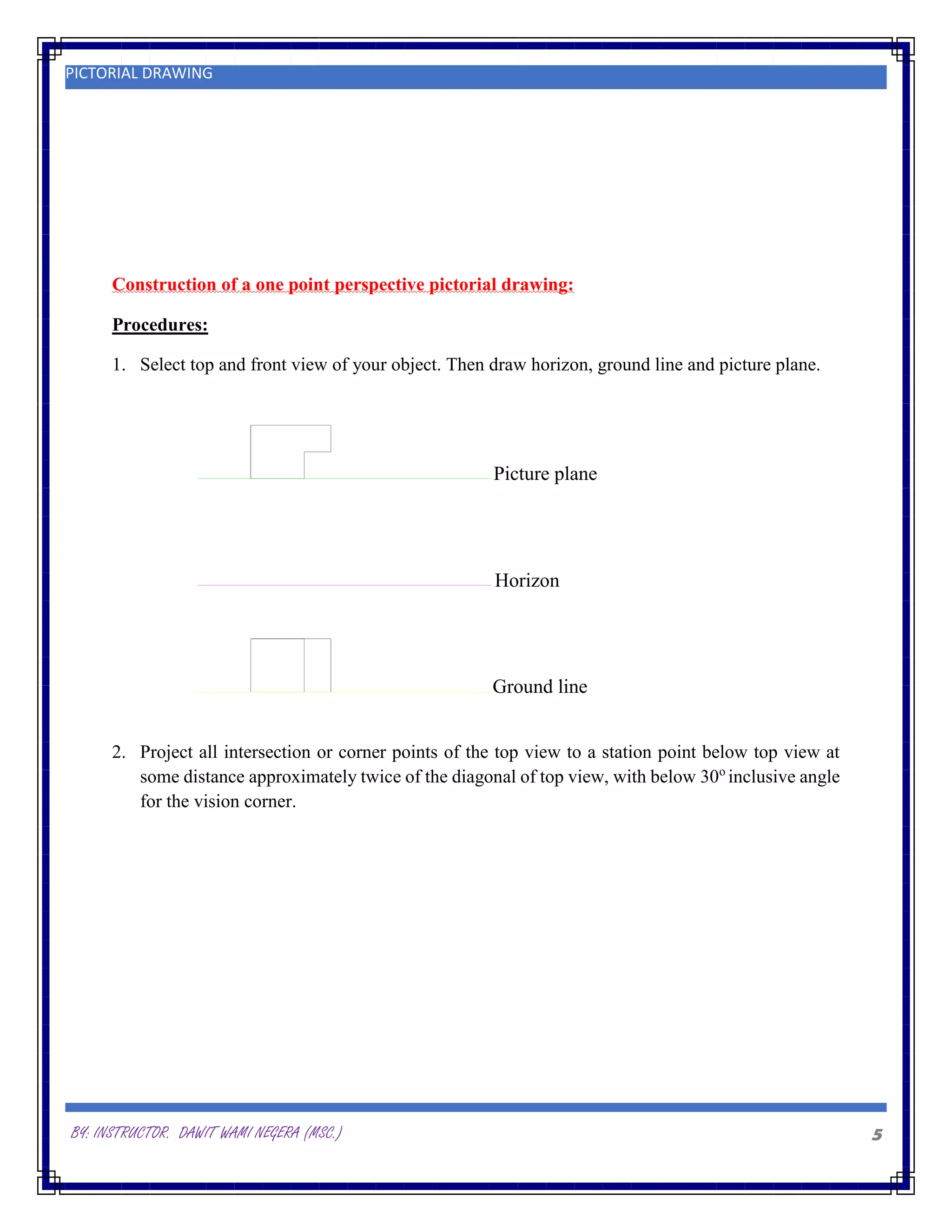
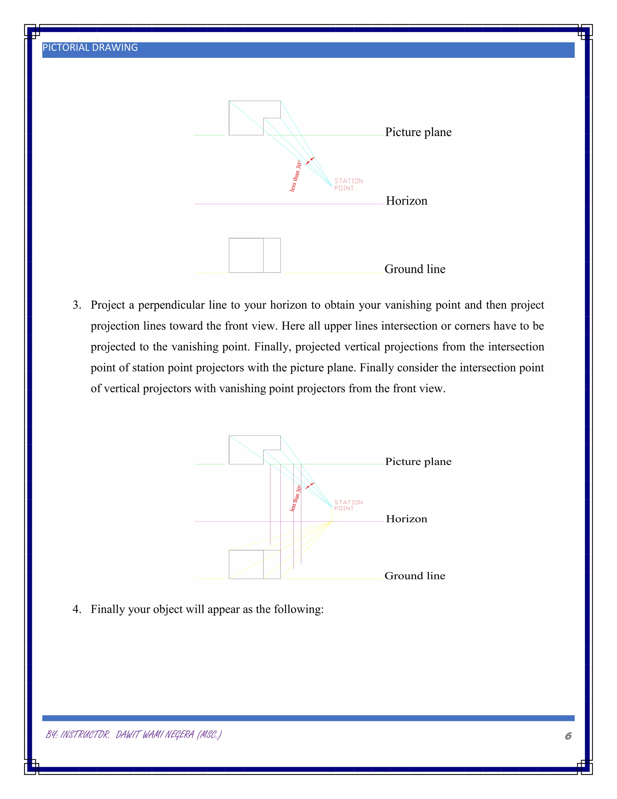
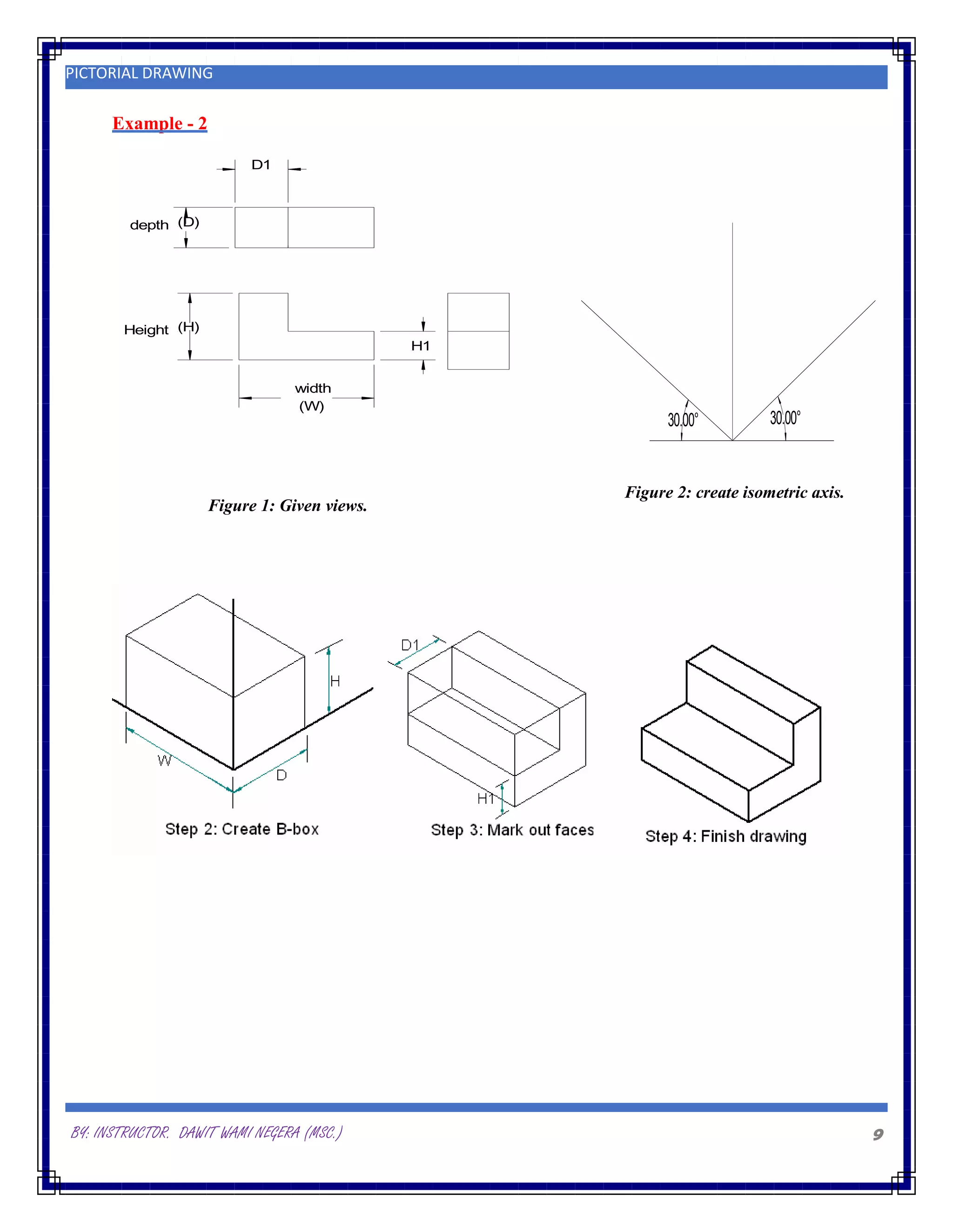
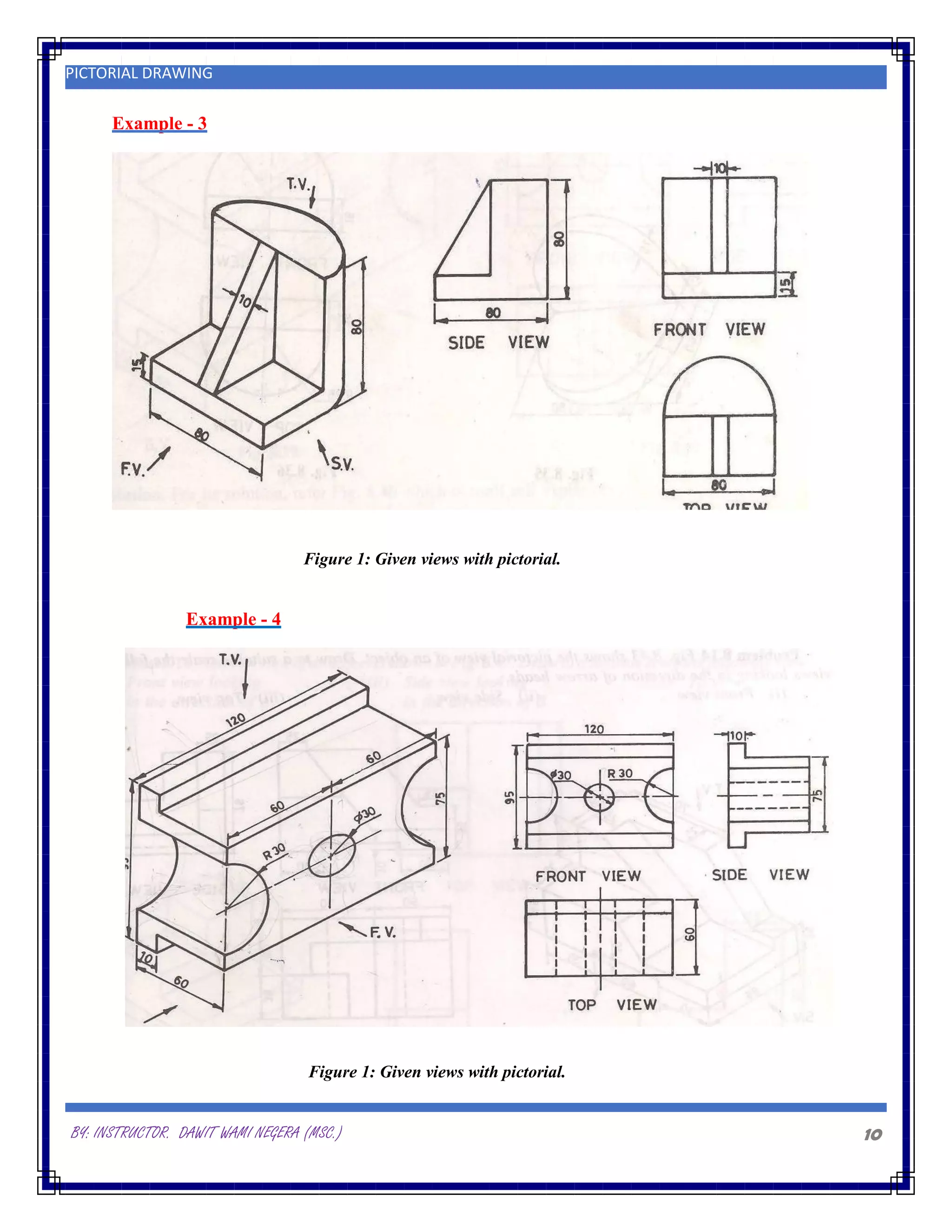
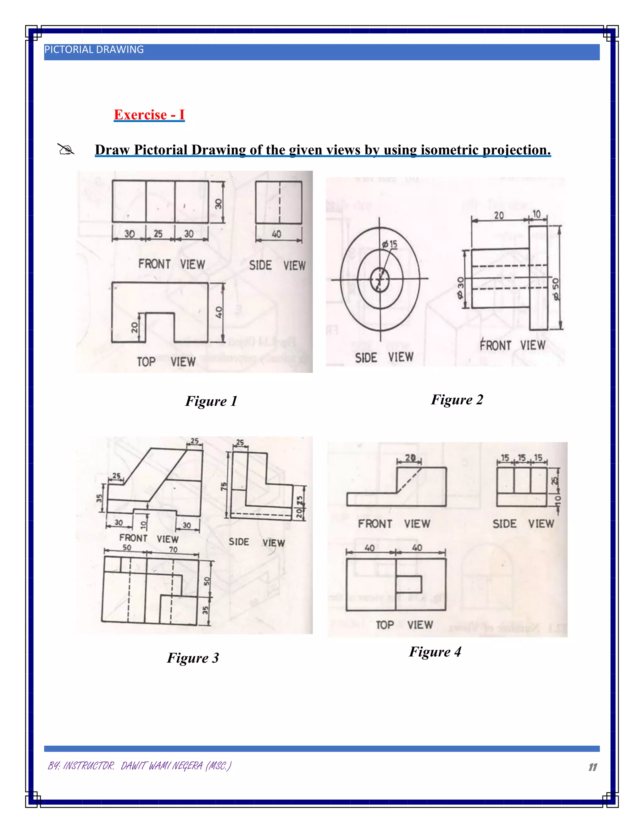
By: Instructor. Dawit Wami Negera (MSc.)
ASSOSA UNIVERSITY, Assosa, Ethiopia
PICTORIAL DRAWING
BY: INSTRUCTOR. DAWIT WAMI NEGERA (MSC.) 1
PICTORIAL DRAWING
45deg
PICTORIAL DRAWING
Definition:
 It is a three dimensional representation of an object.
COMPARISON OF MULTI VIEW DRAWING AND PICTORIAL DRAWING
 Pictorial drawings have the following features to multi view drawing:
Is an effective means of communicating an idea
Shows only the appearances of parts and designs
Extensively used in catalogs of sales, manufacture, maintenance publications, …
Show several sides over a single view
Not satisfactory for complete description of an object
TYPES OF PICTORIAL DRAWING:
The most common types are three. These are:
1. Oblique
2. Axonometric – Isometric
3. Perspective
1. OBLIQUE DRAWING:
It is easiest of the three to draw. But seldom used.
Front view is drawn exactly as it would appear in multi view drawing.
♠ Circles appear as a true circle over the front view.
♠ Rectangles parallel to the frontal plane are in true size.
 You use 3 - axes; two at right angles and one at an angle of convenient, but
most of the time it is preferable to use 45o
.
BY: INSTRUCTOR. DAWIT WAMI NEGERA (MSC.) 2
PICTORIAL DRAWING
 The line of sight should not make an angle less than 45o with the picture plane. This would
result in a receding axis longer than true length, thereby distorting the pictorial.
Advantages:
 Circles or cylinders can easily drawn on the front face in their true shape
 Irregular shapes can be easily sketched on the front view in the same manner.
2. AXONOMETRIC DRAWINGS
 In axonometric drawing the three faces of rectangular object are all inclined to the
plane of projection. Here the observer is considered to be at infinity, and the visual rays are
parallel to each other and perpendicular to the plane of projection.
The three types of axonometric projections. These are:
A. Isometric drawing
B. Diametric drawing
C. Trimetric drawing
A. Isometric drawing
♠ Isometric means equal measure.
♠ Makes equal angle with the principal plane (120o
).
♠ Is the most commonly used axonometric drawing type.
Notice:
Isometric drawing is similar to an Isometric projection except that it is not a true
axonometric projection, but an approximate method of drawing a pictorial.
Isometric projection is foreshortened by 82% of full size. The Isometric drawing is drawn
full size for convenience.
BY: INSTRUCTOR. DAWIT WAMI NEGERA (MSC.) 3
PICTORIAL DRAWING
B. Diametric drawing
Two principal planes have equal angle measurement.
seldom used
C. Trimetric drawing
 All angles measured in principal planes are none equal.
3. PERSPECTIVE DRAWING
 Central projection is the other calling name.
 It excels over all other types of projection in the pictorial representation of objects because it
more closely approximates the view obtained by the human eye.
BY: INSTRUCTOR. DAWIT WAMI NEGERA (MSC.) 4
PICTORIAL DRAWING
Terminology:
 The station of the observer’s eye is called Station point (SP).
 The imaginary plane of projection is called Picture plane (PP).
 The point where all projection lines converge is called vanishing point (VP).
 A horizontal line in the front view representing an infinite horizontal is called Horizon.
The three basic types of perspectives are:
I. One point – single vanishing point
II. Two point – two vanishing point
III. Three point – three vanishing point
ONE POINT PERSPECTIVE DRAWING
Has one surface of the object parallel to the picture plane. However, other sides vanish to a single
point. To draw one point perspective projection, we can develop from top and front views of an
object.
 When drawing any perspective, the station point should be placed far enough away from
the object to permit the cone of vision to be less than 30o
to reduce distortion.
We can work one point perspective either by simply selecting a stationary point or by measuring
points. The use of measuring point eliminates the need of placing top view above the front view.
BY: INSTRUCTOR. DAWIT WAMI NEGERA (MSC.) 5
PICTORIAL DRAWING
Construction of a one point perspective pictorial drawing:
Procedures:
1. Select top and front view of your object. Then draw horizon, ground line and picture plane.
Picture plane
Horizon
Ground line
2. Project all intersection or corner points of the top view to a station point below top view at
some distance approximately twice of the diagonal of top view, with below 30o
inclusive angle
for the vision corner.
BY: INSTRUCTOR. DAWIT WAMI NEGERA (MSC.) 6
PICTORIAL DRAWING
Picture plane
Horizon
Ground line
le
s
s
th
a
n
3
0
°
3. Project a perpendicular line to your horizon to obtain your vanishing point and then project
projection lines toward the front view. Here all upper lines intersection or corners have to be
projected to the vanishing point. Finally, projected vertical projections from the intersection
point of station point projectors with the picture plane. Finally consider the intersection point
of vertical projectors with vanishing point projectors from the front view.
Picture plane
Horizon
Ground line
le
s
s
th
a
n
3
0
°
4. Finally your object will appear as the following:
BY: INSTRUCTOR. DAWIT WAMI NEGERA (MSC.) 7
PICTORIAL DRAWING
Picture plane
Horizon
Ground line
le
s
s
th
a
n
3
0
°
Vanishing
point
Note:
 We can easily sketch one point perspective simply projecting the upper corners of top view
to station point, and upper corners of front view to the vanishing point. It is need not to
project the lower corners of top view which already lay over the picture plane because it
coincides with the edge of front view if we project perpendicular vertical projections.
 In order to obtain accurate shape we have to adjust our cone of vision less than 30o
. If we
increase the angle more, the shape will appear distorted.
BY: INSTRUCTOR. DAWIT WAMI NEGERA (MSC.) 8
PICTORIAL DRAWING
H
W D
Figure 2: Creating B – Box.
Examples:
 Stapes to draw pictorial drawing by the given views in Isometric drawing.
Example - 1
Figure 4: Finish Drawing.
Figure 3: Mark out faces.
Figure 1: Given Views.
BY: INSTRUCTOR. DAWIT WAMI NEGERA (MSC.) 9
PICTORIAL DRAWING
Example - 2
depth
width
Height
(D)
(H)
(W)
H1
D1
30.00°
30.00°
Figure 1: Given views.
Figure 2: create isometric axis.
BY: INSTRUCTOR. DAWIT WAMI NEGERA (MSC.) 10
PICTORIAL DRAWING
Example - 3
Example - 4
Figure 1: Given views with pictorial.
BY: INSTRUCTOR. DAWIT WAMI NEGERA (MSC.) 11
PICTORIAL DRAWING
Exercise - I
 Draw Pictorial Drawing of the given views by using isometric projection.
Figure 1 Figure 2
Figure 4
Figure 3

Pictorial Drawing

  • 1.
    By: Instructor. DawitWami Negera (MSc.) ASSOSA UNIVERSITY, Assosa, Ethiopia PICTORIAL DRAWING
  • 2.
    BY: INSTRUCTOR. DAWITWAMI NEGERA (MSC.) 1 PICTORIAL DRAWING 45deg PICTORIAL DRAWING Definition:  It is a three dimensional representation of an object. COMPARISON OF MULTI VIEW DRAWING AND PICTORIAL DRAWING  Pictorial drawings have the following features to multi view drawing: Is an effective means of communicating an idea Shows only the appearances of parts and designs Extensively used in catalogs of sales, manufacture, maintenance publications, … Show several sides over a single view Not satisfactory for complete description of an object TYPES OF PICTORIAL DRAWING: The most common types are three. These are: 1. Oblique 2. Axonometric – Isometric 3. Perspective 1. OBLIQUE DRAWING: It is easiest of the three to draw. But seldom used. Front view is drawn exactly as it would appear in multi view drawing. ♠ Circles appear as a true circle over the front view. ♠ Rectangles parallel to the frontal plane are in true size.  You use 3 - axes; two at right angles and one at an angle of convenient, but most of the time it is preferable to use 45o .
  • 3.
    BY: INSTRUCTOR. DAWITWAMI NEGERA (MSC.) 2 PICTORIAL DRAWING  The line of sight should not make an angle less than 45o with the picture plane. This would result in a receding axis longer than true length, thereby distorting the pictorial. Advantages:  Circles or cylinders can easily drawn on the front face in their true shape  Irregular shapes can be easily sketched on the front view in the same manner. 2. AXONOMETRIC DRAWINGS  In axonometric drawing the three faces of rectangular object are all inclined to the plane of projection. Here the observer is considered to be at infinity, and the visual rays are parallel to each other and perpendicular to the plane of projection. The three types of axonometric projections. These are: A. Isometric drawing B. Diametric drawing C. Trimetric drawing A. Isometric drawing ♠ Isometric means equal measure. ♠ Makes equal angle with the principal plane (120o ). ♠ Is the most commonly used axonometric drawing type. Notice: Isometric drawing is similar to an Isometric projection except that it is not a true axonometric projection, but an approximate method of drawing a pictorial. Isometric projection is foreshortened by 82% of full size. The Isometric drawing is drawn full size for convenience.
  • 4.
    BY: INSTRUCTOR. DAWITWAMI NEGERA (MSC.) 3 PICTORIAL DRAWING B. Diametric drawing Two principal planes have equal angle measurement. seldom used C. Trimetric drawing  All angles measured in principal planes are none equal. 3. PERSPECTIVE DRAWING  Central projection is the other calling name.  It excels over all other types of projection in the pictorial representation of objects because it more closely approximates the view obtained by the human eye.
  • 5.
    BY: INSTRUCTOR. DAWITWAMI NEGERA (MSC.) 4 PICTORIAL DRAWING Terminology:  The station of the observer’s eye is called Station point (SP).  The imaginary plane of projection is called Picture plane (PP).  The point where all projection lines converge is called vanishing point (VP).  A horizontal line in the front view representing an infinite horizontal is called Horizon. The three basic types of perspectives are: I. One point – single vanishing point II. Two point – two vanishing point III. Three point – three vanishing point ONE POINT PERSPECTIVE DRAWING Has one surface of the object parallel to the picture plane. However, other sides vanish to a single point. To draw one point perspective projection, we can develop from top and front views of an object.  When drawing any perspective, the station point should be placed far enough away from the object to permit the cone of vision to be less than 30o to reduce distortion. We can work one point perspective either by simply selecting a stationary point or by measuring points. The use of measuring point eliminates the need of placing top view above the front view.
  • 6.
    BY: INSTRUCTOR. DAWITWAMI NEGERA (MSC.) 5 PICTORIAL DRAWING Construction of a one point perspective pictorial drawing: Procedures: 1. Select top and front view of your object. Then draw horizon, ground line and picture plane. Picture plane Horizon Ground line 2. Project all intersection or corner points of the top view to a station point below top view at some distance approximately twice of the diagonal of top view, with below 30o inclusive angle for the vision corner.
  • 7.
    BY: INSTRUCTOR. DAWITWAMI NEGERA (MSC.) 6 PICTORIAL DRAWING Picture plane Horizon Ground line le s s th a n 3 0 ° 3. Project a perpendicular line to your horizon to obtain your vanishing point and then project projection lines toward the front view. Here all upper lines intersection or corners have to be projected to the vanishing point. Finally, projected vertical projections from the intersection point of station point projectors with the picture plane. Finally consider the intersection point of vertical projectors with vanishing point projectors from the front view. Picture plane Horizon Ground line le s s th a n 3 0 ° 4. Finally your object will appear as the following:
  • 8.
    BY: INSTRUCTOR. DAWITWAMI NEGERA (MSC.) 7 PICTORIAL DRAWING Picture plane Horizon Ground line le s s th a n 3 0 ° Vanishing point Note:  We can easily sketch one point perspective simply projecting the upper corners of top view to station point, and upper corners of front view to the vanishing point. It is need not to project the lower corners of top view which already lay over the picture plane because it coincides with the edge of front view if we project perpendicular vertical projections.  In order to obtain accurate shape we have to adjust our cone of vision less than 30o . If we increase the angle more, the shape will appear distorted.
  • 9.
    BY: INSTRUCTOR. DAWITWAMI NEGERA (MSC.) 8 PICTORIAL DRAWING H W D Figure 2: Creating B – Box. Examples:  Stapes to draw pictorial drawing by the given views in Isometric drawing. Example - 1 Figure 4: Finish Drawing. Figure 3: Mark out faces. Figure 1: Given Views.
  • 10.
    BY: INSTRUCTOR. DAWITWAMI NEGERA (MSC.) 9 PICTORIAL DRAWING Example - 2 depth width Height (D) (H) (W) H1 D1 30.00° 30.00° Figure 1: Given views. Figure 2: create isometric axis.
  • 11.
    BY: INSTRUCTOR. DAWITWAMI NEGERA (MSC.) 10 PICTORIAL DRAWING Example - 3 Example - 4 Figure 1: Given views with pictorial. Figure 1: Given views with pictorial.
  • 12.
    BY: INSTRUCTOR. DAWITWAMI NEGERA (MSC.) 11 PICTORIAL DRAWING Exercise - I  Draw Pictorial Drawing of the given views by using isometric projection. Figure 1 Figure 2 Figure 4 Figure 3