Downloaded 379 times


](sin2[
11
11
)](sin2[
)](sin2[
11
11
xo
cs
o
x
cs
xI
tV
L
xI
t
L
V
](https://image.slidesharecdn.com/currentcommutatedchopper-150423085708-conversion-gate02/85/Current-commutated-chopper-16-320.jpg)
](sin2[
)](sin2[
11
11
xs
co
x
c
s
o
V
txI
C
C
t
V
xI
](https://image.slidesharecdn.com/currentcommutatedchopper-150423085708-conversion-gate02/85/Current-commutated-chopper-17-320.jpg)


](sin2[230
sec302002
)](sin2[
2
11
11
voltsV
C
L
IVV
CP
osCP
345
822.49
473.16
200230
AxII oCP 4002002 ](https://image.slidesharecdn.com/currentcommutatedchopper-150423085708-conversion-gate02/85/Current-commutated-chopper-22-320.jpg)
](sin2[
12
8183.1
11
11
c
xc
t
LCt](https://image.slidesharecdn.com/currentcommutatedchopper-150423085708-conversion-gate02/85/Current-commutated-chopper-23-320.jpg)


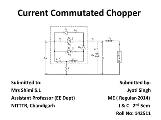
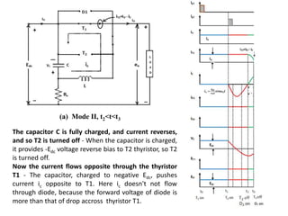
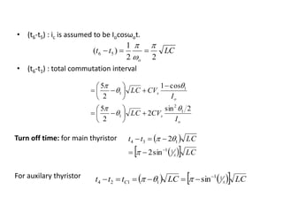
The document discusses the operation and advantages of current commutated choppers, which are used to alter DC voltage levels. It explains the commutation process involving thyristors, capacitors, and inductors, detailing the modes of operation and the conditions necessary for proper function. Additionally, the document includes MATLAB Simulink considerations and numerical examples related to capacitor and inductor values, as well as calculation of turn-off times.


