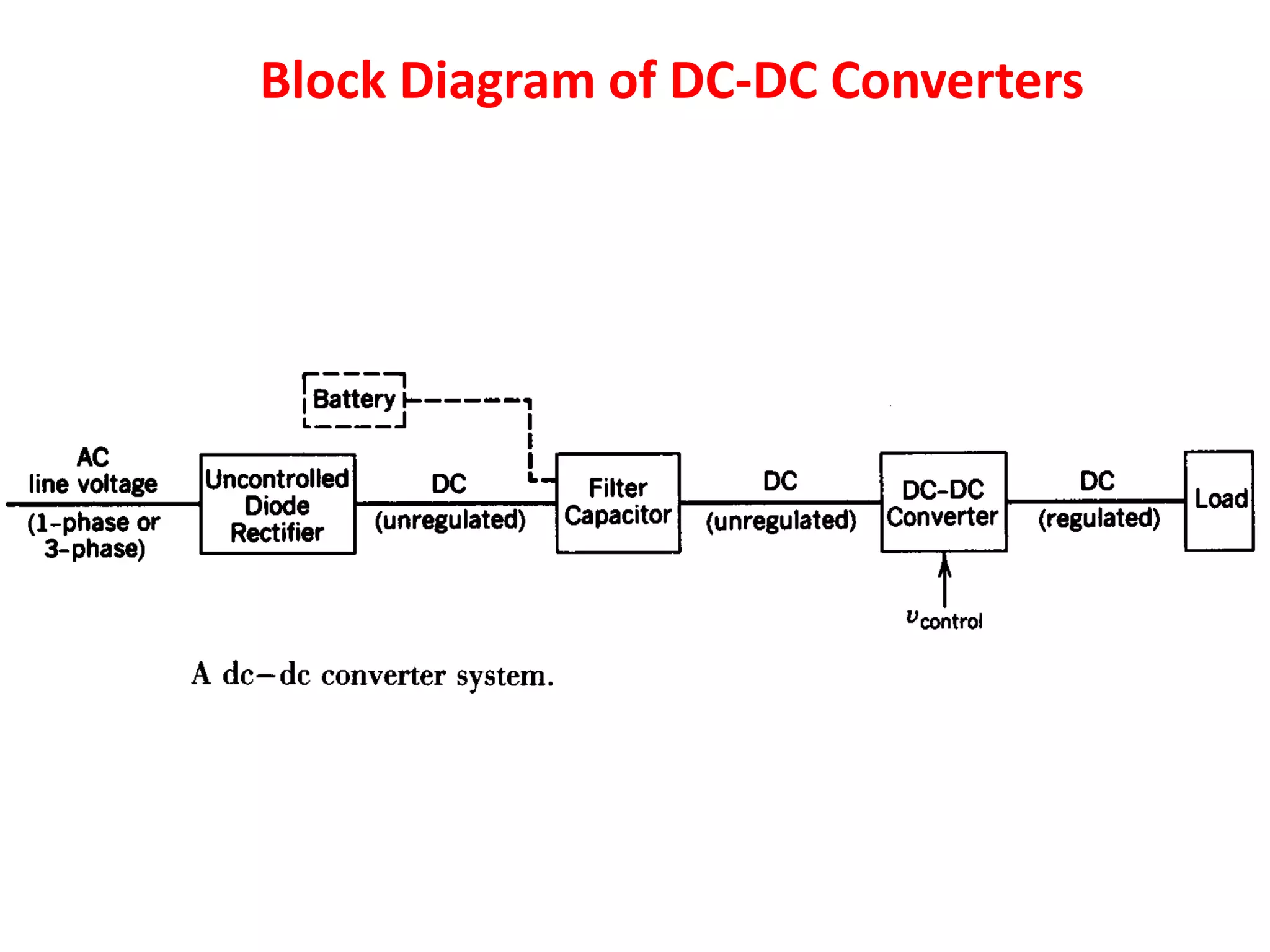
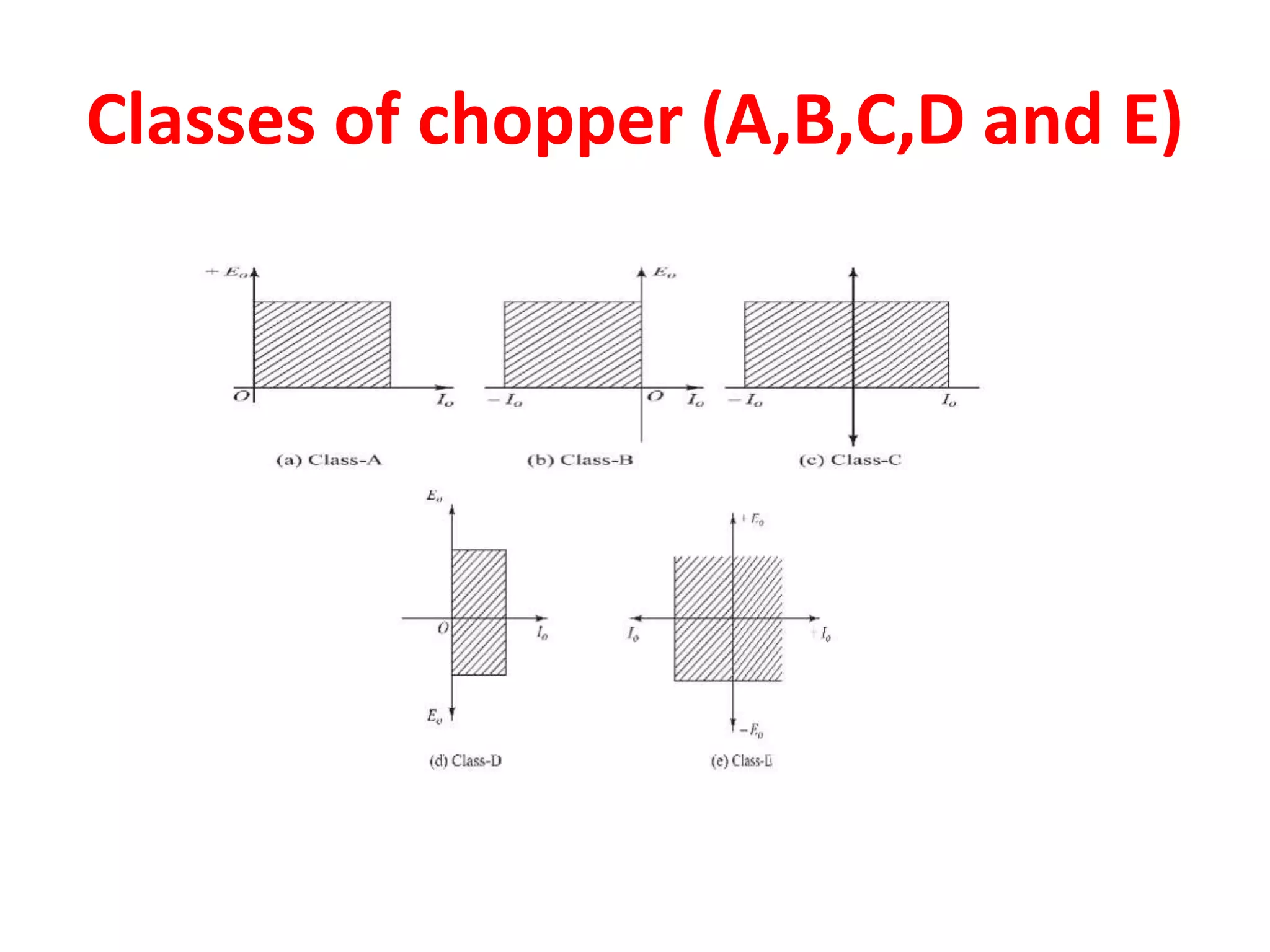
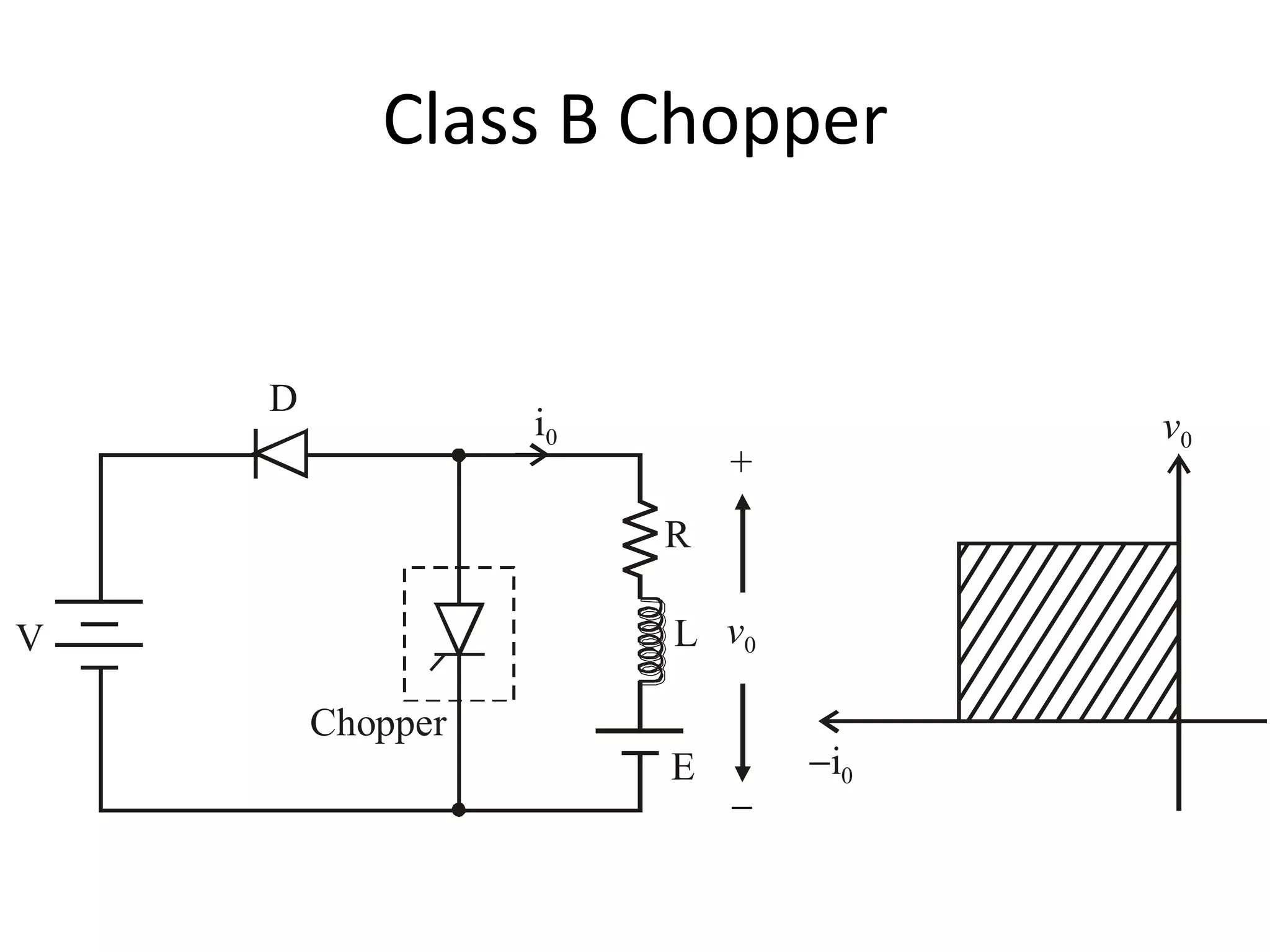
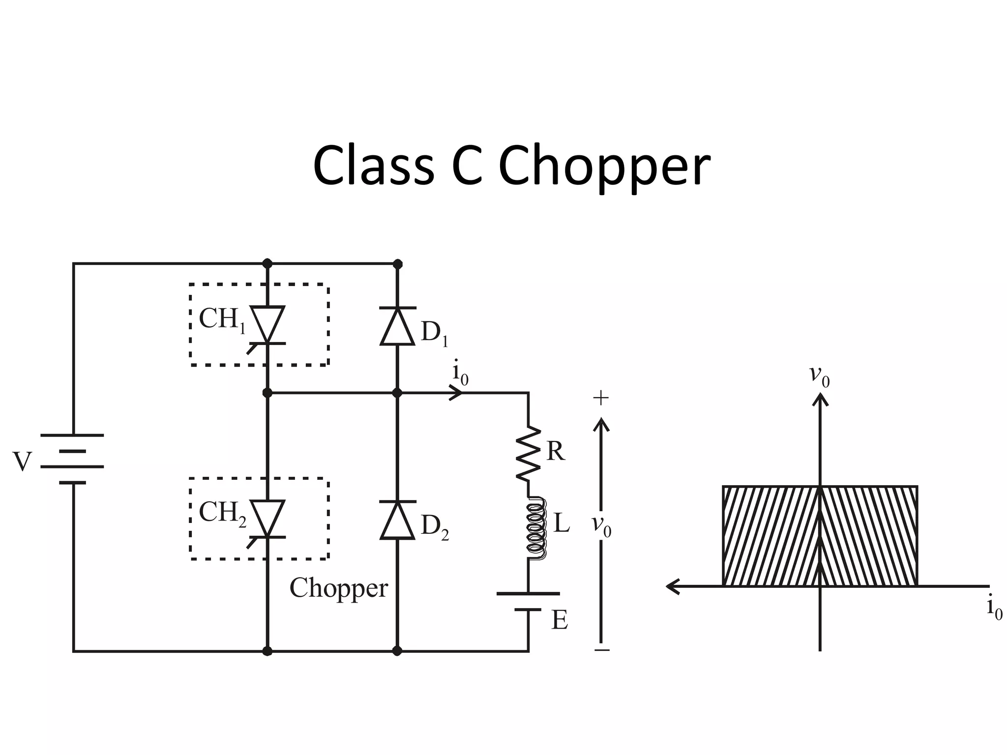
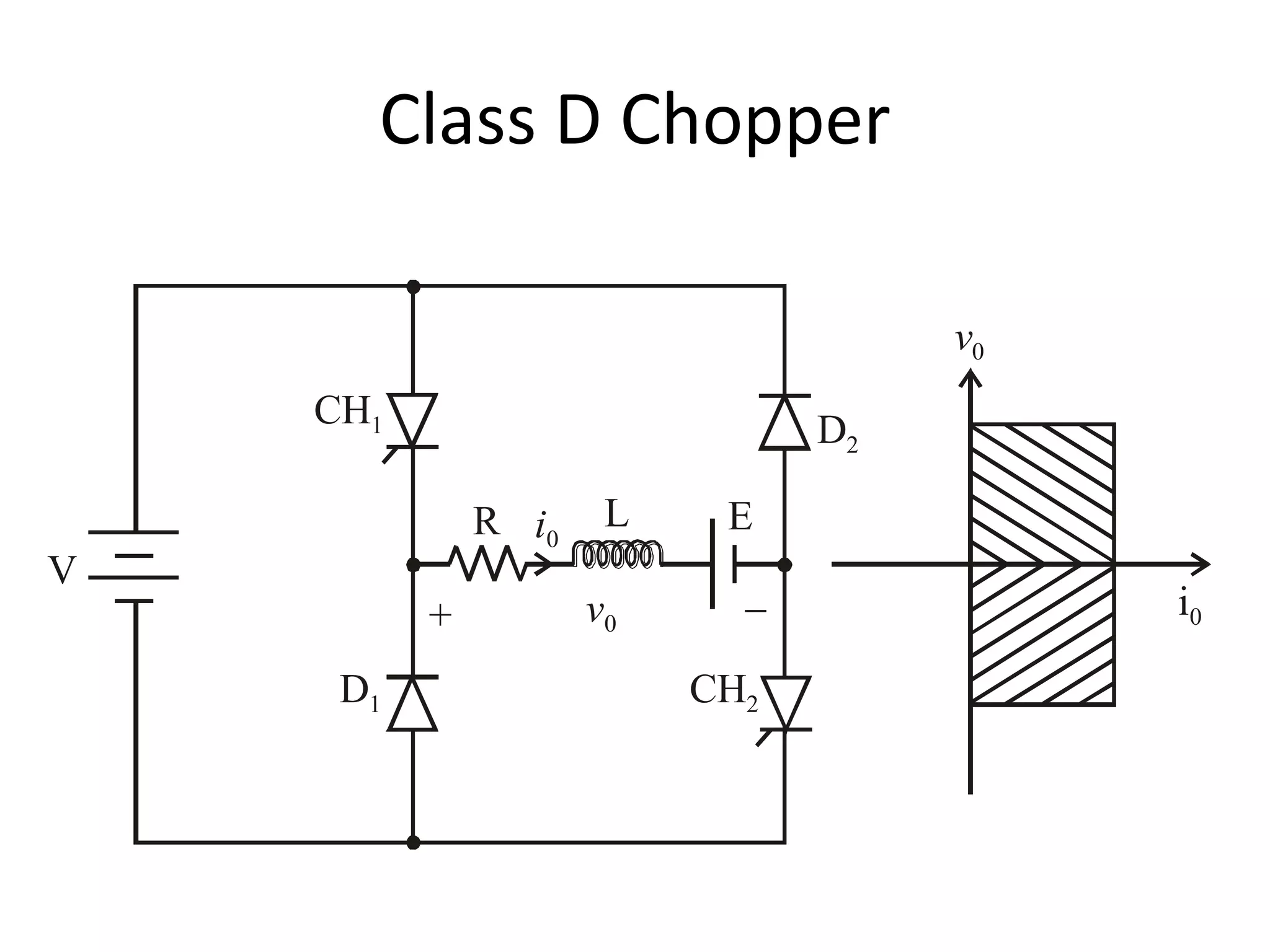
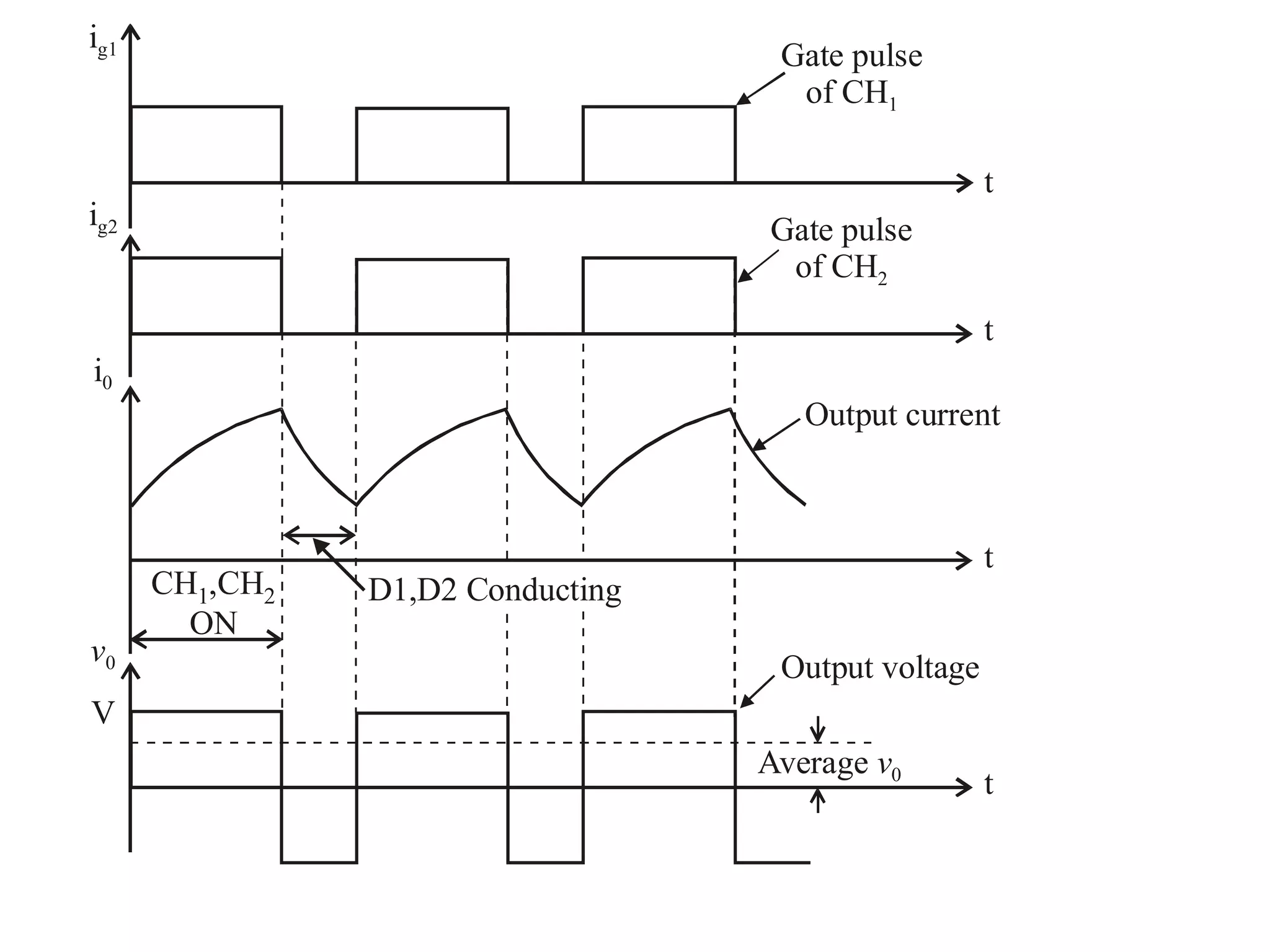
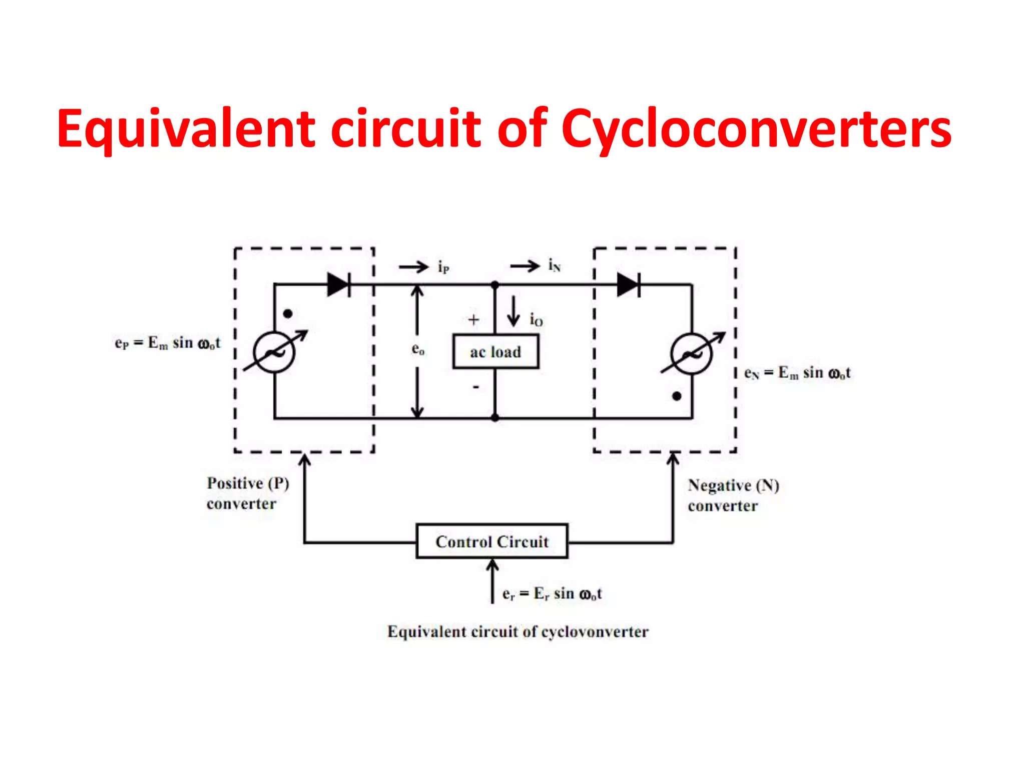
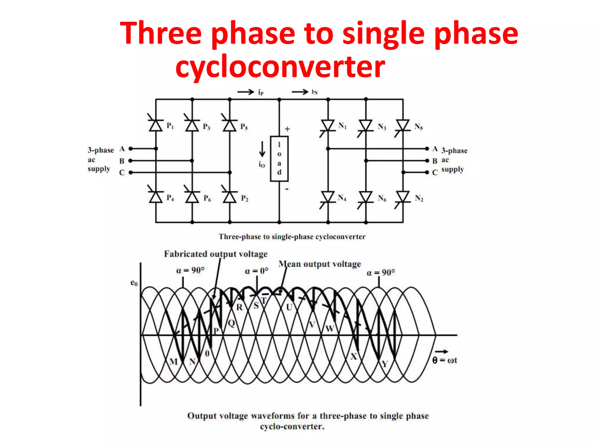
Choppers
Mrs Shimi S L
Assistant Professor, NITTTR,
Chandigarh, India
Introduction
• Chopper is a static device.
• A variable dc voltage is obtained from a
constant dc voltage source.
• Also known as dc-to-dc converter.
• Widely used for motor control, smart grid, ect.
• Also used in regenerative braking.
• Thyristor converter offers greater efficiency,
faster response, lower maintenance, smaller
size and smooth control.
Chopper Controlled DC Motor
Block Diagram of DC-DC Converters
Choppers are of Two Types
 Step-down choppers.
 Step-up choppers.
 In step down chopper output voltage is less
than input voltage.
 In step up chopper output voltage is more
than input voltage.
Classification of Chopper
Based on input/output voltage levels
• Step-down Chopper (Buck converter)
• Step-up Chopper (Boost Converter)
• Buck Boost Converter
Direction of output voltage and current
• Class A
• Class B
• Class C
• Class D
Based on Circuit operation
• First (Single) Quadrant Chopper
• Two-quadrant Chopper
• Four Quadrant Chopper
Based on Commutation Method
• Voltage Commuted Chopper
• Current Commuted Chopper
• Load commuted Chopper
• Impulse Commuted Chopper
Classes of chopper (A,B,C,D and E)
Control Strategies
• The output dc voltage can be varied by the
following methods.
• (a) Time-ratio control, and
– Pulse width modulation control or constant
frequency operation.
– Variable frequency control.
• (b) Current limit control
Pulse Width Modulation
or
Constant Frequency Operation
• tON is varied keeping chopping frequency ‘f’ &
chopping period ‘T’ constant.
• Output voltage is varied by varying the ON
time tON
V0
V
V
V0
t
t
tON
tON tOFF
tOFF
T
Variable Frequency Control
• Chopping frequency ‘f’ is varied keeping either
tON or tOFF constant.
• To obtain full output voltage range, frequency
has to be varied over a wide range.
• This method produces harmonics in the output
and for large tOFF load current may become
discontinuous
Disadvantages of Variable Frequency
Control Strategy
(a) The frequency has to be varied over a wide range for the
control of output voltage in frequency modulation. Filter
design for such wide frequency variation is, therefore, quite
difficult.
(b) For the control of a duty ratio, frequency variation would be
wide. As such, there is a possibly of interference with systems
using certain frequencies, such as signaling and telephone
line, in frequency modulation technique.
(c) The large OFF time in frequency modulation technique, may
make the load current discontinuous, which is undesirable.
Thus, the constant frequency system using PWM is the preferred
scheme for dc-dc converters (choppers).
Current Limit Control
Stepping Down a DC Voltage
• A simple approach that shows the evolution
Pulse-Width Modulation in DC-DC Converters
Step-Down DC-DC Converter: Waveforms
Step-Up DC-DC Converter
Step-Up DC-DC Converter : Waveform
Step-Down/Up DC-DC Converter
• The output voltage can be higher or lower than the
input voltage
Step-Down/Up DC-DC Converter : Waveform
Classification Of Choppers
• Choppers are classified as
–Class A Chopper
–Class B Chopper
–Class C Chopper
–Class D Chopper
–Class E Chopper
Class A Chopper
V
Chopper
FWD
+

v0
v0
i0
i0
L
O
A
D
V
• When chopper is ON, supply voltage V is
connected across the load.
• When chopper is OFF, vO = 0 and the load
current continues to flow in the same direction
through the FWD.
• The average values of output voltage and
current are always positive.
• Class A Chopper is a first quadrant chopper .
• Class A Chopper is a step-down chopper in
which power always flows form source to load.
• It is used to control the speed of dc motor.
• The output current equations obtained in step
down chopper with R-L load can be used to
study the performance of Class A Chopper.
Output current
Thyristor
gate pulse
Output voltage
ig
i0
v0
t
t
t
tON
T
CH ON
FWD Conducts
Class B Chopper
V
Chopper
+

v0
v0
i0
i0
L
E
R
D
• When chopper is ON, E drives a current
through L and R in a direction opposite to that
shown in figure.
• During the ON period of the chopper, the
inductance L stores energy.
• When Chopper is OFF, diode D conducts, and
part of the energy stored in inductor L is
returned to the supply.
• When chopper is ON, E drives a current
through L and R in a direction opposite to that
shown in figure.
• During the ON period of the chopper, the
inductance L stores energy.
• When Chopper is OFF, diode D conducts, and
part of the energy stored in inductor L is
returned to the supply.
Output current
D
conducts Chopper
conducts
Thyristor
gate pulse
Output voltage
ig
i0
v0
t
t
t
Imin
Imax
T
tONtOFF
Class C Chopper
V
Chopper
+

v0
D1
D2
CH2
CH1
v0
i0
i0
L
E
R
• Class C Chopper is a combination of Class A
and Class B Choppers.
• For first quadrant operation, CH1 is ON or D2
conducts.
• For second quadrant operation, CH2 is ON or
D1 conducts.
• When CH1 is ON, the load current is positive.
• The output voltage is equal to ‘V’ & the load
receives power from the source.
• When CH1 is turned OFF, energy stored in
inductance L forces current to flow through
the diode D2 and the output voltage is zero.
• Current continues to flow in positive direction.
• When CH2 is triggered, the voltage E forces
current to flow in opposite direction through L
and CH2 .
• The output voltage is zero.
• On turning OFF CH2 , the energy stored in the
inductance drives current through diode D1
and the supply
• Output voltage is V, the input current becomes
negative and power flows from load to source.
• Average output voltage is positive
• Average output current can take both positive
and negative values.
• Choppers CH1 & CH2 should not be turned ON
simultaneously as it would result in short
circuiting the supply.
• Class C Chopper can be used both for dc motor
control and regenerative braking of dc motor.
• Class C Chopper can be used as a step-up or
step-down chopper.
Gate pulse
of CH2
Gate pulse
of CH1
Output current
Output voltage
ig1
ig2
i0
V0
t
t
t
t
D1 D1D2 D2CH1 CH2 CH1 CH2
ON ON ON ON
Class D Chopper
V
+ v0
D2
D1 CH2
CH1
v0
i0
L ER i0
• Class D is a two quadrant chopper.
• When both CH1 and CH2 are triggered
simultaneously, the output voltage vO = V and
output current flows through the load.
• When CH1 and CH2 are turned OFF, the load
current continues to flow in the same direction
through load, D1 and D2 , due to the energy
stored in the inductor L.
• Output voltage vO = - V .
• Average load voltage is positive if chopper ON
time is more than the OFF time
• Average output voltage becomes negative if
tON < tOFF .
• Hence the direction of load current is always
positive but load voltage can be positive or
negative.
Gate pulse
of CH2
Gate pulse
of CH1
Output current
Output voltage
Average v0
ig1
ig2
i0
v0
V
t
t
t
t
CH ,CH
ON
1 2 D1,D2 Conducting
Gate pulse
of CH2
Gate pulse
of CH1
Output current
Output voltage
Average v0
ig1
ig2
i0
v0
V
t
t
t
t
CH
CH
1
2
D , D1 2
Class E Chopper
V
v0
i0
L ER
CH2 CH4D2 D4
D1 D3
CH1 CH3
+ 
Four Quadrant Operation
v0
i0
CH - CH ON
CH - D Conducts
1 4
4 2
D D2 3- Conducts
CH - D Conducts4 2
CH - CH ON
CH - D Conducts
3 2
2 4
CH - D Conducts
D - D Conducts
2 4
1 4
• Class E is a four quadrant chopper
• When CH1 and CH4 are triggered, output
current iO flows in positive direction through
CH1 and CH4, and with output voltage vO = V.
• This gives the first quadrant operation.
• When both CH1 and CH4 are OFF, the energy
stored in the inductor L drives iO through D2
and D3 in the same direction, but output
voltage vO = -V.
• Therefore the chopper operates in the fourth
quadrant.
• When CH2 and CH3 are triggered, the load current iO
flows in opposite direction & output voltage vO = -V.
• Since both iO and vO are negative, the chopper
operates in third quadrant.
• When both CH2 and CH3 are OFF, the load current iO
continues to flow in the same direction D1 and D4 and
the output voltage vO = V.
• Therefore the chopper operates in second quadrant
as vO is positive but iO is negative.
Commutation in DC-DC Choppers
i) Voltage commutation
ii) Current commutation
iii) Load commutation
Voltage Commutation
Different Modes of Voltage Commutation Chopper
Current commutation
Different Modes of Current Commutation Chopper
Cycloconverters
Types of cycloconverters
• Step-down cycloconverters ( fo<fs )
• Step-up cycloconverters ( fs<fo )
Applications
• Speed control of high power ac drives
• Induction heating
• Static VAR generation
• Power supply in aircraft or shipboards
Equivalent circuit of Cycloconverters
Single phase to single phase
step up cycloconverter
Mid-point Cycloconverter Wave form
P1 -> Forward biased ,ON
N2 -> Forward biased ,OFF
P2,N1 -> Reverse biased
P1 -> Forward biased ,OFF
N2 -> Forward biased ,ON
P2,N1 -> Reverse biased
Bridge Type Cycloconverter Wave form
Single phase to single phase
step up cycloconverter
P1,P2 -> Forward biased ,ON
N,N2 -> Forward biased ,OFF
P3,P4,N3,N4 -> Reverse biased
P1,P2 -> Forward biased ,OFF
N,N2 -> Forward biased ,ON
P3,P4,N3,N4 -> Reverse biased
RL Load Wave form
P1 P2 P1 P2 N2 N1 N2 N1
Resistive Load Wave form
Three phase to single phase
cycloconverter
• Gating circuitry is suitably designed to introduce
progressive firing angle dealy.
• Vary progressively the firing angle of the thyristors, firing
angle at M = 90°
at N < 90°
• At O angle is further reduced than it is at N and so on.
In this way , a small delay in firing angle is introduced at
O, P, G, R and S.
• At S firing angle = 0°,
o The mean output voltage, given
Vo=Vdocos∝
and is maximum at S.
• At M,
V= 0 as α = 90°
• After point S, a small delay in firing angle is
further produced progressively at points T, U, V,
W, X and Y.
• At Y, the firing angle is again 90° and mean
output voltage is 0.
• Mean output voltage wave is obtained by joining
points pertaining to average voltage values.
fabricated output voltage is
shown by thick curve
Fabricated output voltage = Fundamental
frequency output voltage + several other
harmonic components
High frequency components
Can be eliminated by
Low Inductance
The Fig, shows half-cycle of fundamental frequency
output voltage (marked mean output voltage), there
are eight half cycles of supply frequency voltage,
i.e.
fo =1/8 fs
Where fs is the supply frequency.
• For obtaining positive half cycle of low-frequency
output voltage, firing angle is varied from 90° to 0°
and
90° to 0°.
• For obtaining one cycle (consisting of one positive half
cycle and one negative half cycle)of low frequency
output voltage,
Firing angle 90° to 0 to 90° for +ve half cycle and from
90° to 180° and back to 90° for –ve half cycle.
Magnitude of progressive change in firing angle
= (reduction factor in frequency)x 120°
Progressive step variation in firing angle
= 1/8 x 120°=15°
α = 90° at M
α = 90° - 15° = 75° at N
α = 75° - 15° = 60° at O
α = 60° - 15° = 45° at P
α = 45° - 15° = 30° at Q
α = 30° - 15° = 15° at R
α = 15° - 15° = 0° at S and so on till α = 90° at Y
From M to Y, there is one half cycle of low frequency
output voltage and eight half cycle of supply
frequency, Indicating,
fo =1/8 fs
Anti-Parallel connection of two three-phase half-
wave converters allows flow of current in both
directions
Positive converter group permits the flow
of current during positive half cycle
Negative converter group permits the flow
of current during negative half cycle
Fig.4 ( a) Voltage waveform (b) Current waveform
Three phase to single phase
cycloconverter
(a) Schematic Diagram (b) Wave form
Three phase to three phase
cycloconverter
Advantages and Disadvantages of Cyclo-converter
Advantages
1. In a cyclo-converter, ac power at one frequency is converted directly to a lower
frequency in a single conversion stage.
2. Cyclo-converter functions by means of phase commutation, without auxiliary forced
commutation circuits. The power circuit is more compact, eliminating circuit losses
associated with forced commutation.
3. Cyclo-converter is inherently capable of power transfer in either direction between
source and load. It can supply power to loads at any power factor, and is also capable of
regeneration over the complete speed range, down to standstill. This feature makes it
preferable for large reversing drives requiring rapid acceleration and deceleration, thus
suited for metal rolling application.
4. Commutation failure causes a short circuit of ac supply. But, if an individual fuse blows
off, a complete shutdown is not necessary, and cyclo-converter continues to function with
somewhat distorted waveforms. A balanced load is presented to the ac supply with
unbalanced output conditions.
5. Cyclo-converter delivers a high quality sinusoidal waveform at low output frequencies,
since it is fabricated from a large number of segments of the supply waveform. This is
often preferable for very low speed applications.
6. Cyclo-converter is extremely attractive for large power, low speed drives.
Disadvantages
1. Large number of thyristors is required in a cyclo-converter, and its control
circuitry becomes more complex. It is not justified to use it for small
installations, but is economical for units above 20 kVA.
2. For reasonable power output and efficiency, the output frequency is
limited to one-third of the input frequency.
3. The power factor is low particularly at reduced output voltages, as phase
control is used with high firing delay angle.

Choppers and cycloconverters

  • 1.
    Choppers Mrs Shimi SL Assistant Professor, NITTTR, Chandigarh, India
  • 2.
    Introduction • Chopper isa static device. • A variable dc voltage is obtained from a constant dc voltage source. • Also known as dc-to-dc converter. • Widely used for motor control, smart grid, ect. • Also used in regenerative braking. • Thyristor converter offers greater efficiency, faster response, lower maintenance, smaller size and smooth control.
  • 3.
  • 5.
    Block Diagram ofDC-DC Converters
  • 6.
    Choppers are ofTwo Types  Step-down choppers.  Step-up choppers.  In step down chopper output voltage is less than input voltage.  In step up chopper output voltage is more than input voltage.
  • 7.
    Classification of Chopper Basedon input/output voltage levels • Step-down Chopper (Buck converter) • Step-up Chopper (Boost Converter) • Buck Boost Converter Direction of output voltage and current • Class A • Class B • Class C • Class D
  • 8.
    Based on Circuitoperation • First (Single) Quadrant Chopper • Two-quadrant Chopper • Four Quadrant Chopper Based on Commutation Method • Voltage Commuted Chopper • Current Commuted Chopper • Load commuted Chopper • Impulse Commuted Chopper
  • 9.
    Classes of chopper(A,B,C,D and E)
  • 10.
    Control Strategies • Theoutput dc voltage can be varied by the following methods. • (a) Time-ratio control, and – Pulse width modulation control or constant frequency operation. – Variable frequency control. • (b) Current limit control
  • 11.
    Pulse Width Modulation or ConstantFrequency Operation • tON is varied keeping chopping frequency ‘f’ & chopping period ‘T’ constant. • Output voltage is varied by varying the ON time tON
  • 12.
  • 13.
    Variable Frequency Control •Chopping frequency ‘f’ is varied keeping either tON or tOFF constant. • To obtain full output voltage range, frequency has to be varied over a wide range. • This method produces harmonics in the output and for large tOFF load current may become discontinuous
  • 15.
    Disadvantages of VariableFrequency Control Strategy (a) The frequency has to be varied over a wide range for the control of output voltage in frequency modulation. Filter design for such wide frequency variation is, therefore, quite difficult. (b) For the control of a duty ratio, frequency variation would be wide. As such, there is a possibly of interference with systems using certain frequencies, such as signaling and telephone line, in frequency modulation technique. (c) The large OFF time in frequency modulation technique, may make the load current discontinuous, which is undesirable. Thus, the constant frequency system using PWM is the preferred scheme for dc-dc converters (choppers).
  • 16.
  • 17.
    Stepping Down aDC Voltage • A simple approach that shows the evolution
  • 18.
    Pulse-Width Modulation inDC-DC Converters
  • 19.
  • 20.
  • 21.
  • 22.
  • 23.
    Step-Down/Up DC-DC Converter •The output voltage can be higher or lower than the input voltage
  • 24.
  • 25.
    Classification Of Choppers •Choppers are classified as –Class A Chopper –Class B Chopper –Class C Chopper –Class D Chopper –Class E Chopper
  • 26.
  • 27.
    • When chopperis ON, supply voltage V is connected across the load. • When chopper is OFF, vO = 0 and the load current continues to flow in the same direction through the FWD. • The average values of output voltage and current are always positive. • Class A Chopper is a first quadrant chopper .
  • 28.
    • Class AChopper is a step-down chopper in which power always flows form source to load. • It is used to control the speed of dc motor. • The output current equations obtained in step down chopper with R-L load can be used to study the performance of Class A Chopper.
  • 29.
    Output current Thyristor gate pulse Outputvoltage ig i0 v0 t t t tON T CH ON FWD Conducts
  • 30.
  • 31.
    • When chopperis ON, E drives a current through L and R in a direction opposite to that shown in figure. • During the ON period of the chopper, the inductance L stores energy. • When Chopper is OFF, diode D conducts, and part of the energy stored in inductor L is returned to the supply.
  • 32.
    • When chopperis ON, E drives a current through L and R in a direction opposite to that shown in figure. • During the ON period of the chopper, the inductance L stores energy. • When Chopper is OFF, diode D conducts, and part of the energy stored in inductor L is returned to the supply.
  • 33.
    Output current D conducts Chopper conducts Thyristor gatepulse Output voltage ig i0 v0 t t t Imin Imax T tONtOFF
  • 34.
  • 35.
    • Class CChopper is a combination of Class A and Class B Choppers. • For first quadrant operation, CH1 is ON or D2 conducts. • For second quadrant operation, CH2 is ON or D1 conducts. • When CH1 is ON, the load current is positive. • The output voltage is equal to ‘V’ & the load receives power from the source. • When CH1 is turned OFF, energy stored in inductance L forces current to flow through the diode D2 and the output voltage is zero.
  • 36.
    • Current continuesto flow in positive direction. • When CH2 is triggered, the voltage E forces current to flow in opposite direction through L and CH2 . • The output voltage is zero. • On turning OFF CH2 , the energy stored in the inductance drives current through diode D1 and the supply • Output voltage is V, the input current becomes negative and power flows from load to source.
  • 37.
    • Average outputvoltage is positive • Average output current can take both positive and negative values. • Choppers CH1 & CH2 should not be turned ON simultaneously as it would result in short circuiting the supply. • Class C Chopper can be used both for dc motor control and regenerative braking of dc motor. • Class C Chopper can be used as a step-up or step-down chopper.
  • 38.
    Gate pulse of CH2 Gatepulse of CH1 Output current Output voltage ig1 ig2 i0 V0 t t t t D1 D1D2 D2CH1 CH2 CH1 CH2 ON ON ON ON
  • 39.
    Class D Chopper V +v0 D2 D1 CH2 CH1 v0 i0 L ER i0
  • 40.
    • Class Dis a two quadrant chopper. • When both CH1 and CH2 are triggered simultaneously, the output voltage vO = V and output current flows through the load. • When CH1 and CH2 are turned OFF, the load current continues to flow in the same direction through load, D1 and D2 , due to the energy stored in the inductor L. • Output voltage vO = - V .
  • 41.
    • Average loadvoltage is positive if chopper ON time is more than the OFF time • Average output voltage becomes negative if tON < tOFF . • Hence the direction of load current is always positive but load voltage can be positive or negative.
  • 42.
    Gate pulse of CH2 Gatepulse of CH1 Output current Output voltage Average v0 ig1 ig2 i0 v0 V t t t t CH ,CH ON 1 2 D1,D2 Conducting
  • 43.
    Gate pulse of CH2 Gatepulse of CH1 Output current Output voltage Average v0 ig1 ig2 i0 v0 V t t t t CH CH 1 2 D , D1 2
  • 44.
    Class E Chopper V v0 i0 LER CH2 CH4D2 D4 D1 D3 CH1 CH3 + 
  • 45.
    Four Quadrant Operation v0 i0 CH- CH ON CH - D Conducts 1 4 4 2 D D2 3- Conducts CH - D Conducts4 2 CH - CH ON CH - D Conducts 3 2 2 4 CH - D Conducts D - D Conducts 2 4 1 4
  • 46.
    • Class Eis a four quadrant chopper • When CH1 and CH4 are triggered, output current iO flows in positive direction through CH1 and CH4, and with output voltage vO = V. • This gives the first quadrant operation. • When both CH1 and CH4 are OFF, the energy stored in the inductor L drives iO through D2 and D3 in the same direction, but output voltage vO = -V.
  • 47.
    • Therefore thechopper operates in the fourth quadrant. • When CH2 and CH3 are triggered, the load current iO flows in opposite direction & output voltage vO = -V. • Since both iO and vO are negative, the chopper operates in third quadrant. • When both CH2 and CH3 are OFF, the load current iO continues to flow in the same direction D1 and D4 and the output voltage vO = V. • Therefore the chopper operates in second quadrant as vO is positive but iO is negative.
  • 48.
    Commutation in DC-DCChoppers i) Voltage commutation ii) Current commutation iii) Load commutation
  • 49.
  • 50.
    Different Modes ofVoltage Commutation Chopper
  • 51.
  • 52.
    Different Modes ofCurrent Commutation Chopper
  • 53.
  • 54.
    Types of cycloconverters •Step-down cycloconverters ( fo<fs ) • Step-up cycloconverters ( fs<fo ) Applications • Speed control of high power ac drives • Induction heating • Static VAR generation • Power supply in aircraft or shipboards
  • 55.
    Equivalent circuit ofCycloconverters
  • 57.
    Single phase tosingle phase step up cycloconverter Mid-point Cycloconverter Wave form
  • 58.
    P1 -> Forwardbiased ,ON N2 -> Forward biased ,OFF P2,N1 -> Reverse biased P1 -> Forward biased ,OFF N2 -> Forward biased ,ON P2,N1 -> Reverse biased
  • 59.
    Bridge Type CycloconverterWave form Single phase to single phase step up cycloconverter
  • 60.
    P1,P2 -> Forwardbiased ,ON N,N2 -> Forward biased ,OFF P3,P4,N3,N4 -> Reverse biased
  • 61.
    P1,P2 -> Forwardbiased ,OFF N,N2 -> Forward biased ,ON P3,P4,N3,N4 -> Reverse biased
  • 62.
    RL Load Waveform P1 P2 P1 P2 N2 N1 N2 N1
  • 63.
  • 64.
    Three phase tosingle phase cycloconverter
  • 65.
    • Gating circuitryis suitably designed to introduce progressive firing angle dealy. • Vary progressively the firing angle of the thyristors, firing angle at M = 90° at N < 90° • At O angle is further reduced than it is at N and so on. In this way , a small delay in firing angle is introduced at O, P, G, R and S. • At S firing angle = 0°, o The mean output voltage, given Vo=Vdocos∝ and is maximum at S. • At M, V= 0 as α = 90°
  • 66.
    • After pointS, a small delay in firing angle is further produced progressively at points T, U, V, W, X and Y. • At Y, the firing angle is again 90° and mean output voltage is 0. • Mean output voltage wave is obtained by joining points pertaining to average voltage values. fabricated output voltage is shown by thick curve
  • 67.
    Fabricated output voltage= Fundamental frequency output voltage + several other harmonic components High frequency components Can be eliminated by Low Inductance
  • 68.
    The Fig, showshalf-cycle of fundamental frequency output voltage (marked mean output voltage), there are eight half cycles of supply frequency voltage, i.e. fo =1/8 fs Where fs is the supply frequency. • For obtaining positive half cycle of low-frequency output voltage, firing angle is varied from 90° to 0° and 90° to 0°.
  • 69.
    • For obtainingone cycle (consisting of one positive half cycle and one negative half cycle)of low frequency output voltage, Firing angle 90° to 0 to 90° for +ve half cycle and from 90° to 180° and back to 90° for –ve half cycle. Magnitude of progressive change in firing angle = (reduction factor in frequency)x 120° Progressive step variation in firing angle = 1/8 x 120°=15°
  • 70.
    α = 90°at M α = 90° - 15° = 75° at N α = 75° - 15° = 60° at O α = 60° - 15° = 45° at P α = 45° - 15° = 30° at Q α = 30° - 15° = 15° at R α = 15° - 15° = 0° at S and so on till α = 90° at Y From M to Y, there is one half cycle of low frequency output voltage and eight half cycle of supply frequency, Indicating, fo =1/8 fs
  • 71.
    Anti-Parallel connection oftwo three-phase half- wave converters allows flow of current in both directions Positive converter group permits the flow of current during positive half cycle Negative converter group permits the flow of current during negative half cycle
  • 72.
    Fig.4 ( a)Voltage waveform (b) Current waveform
  • 73.
    Three phase tosingle phase cycloconverter (a) Schematic Diagram (b) Wave form
  • 74.
    Three phase tothree phase cycloconverter
  • 77.
    Advantages and Disadvantagesof Cyclo-converter Advantages 1. In a cyclo-converter, ac power at one frequency is converted directly to a lower frequency in a single conversion stage. 2. Cyclo-converter functions by means of phase commutation, without auxiliary forced commutation circuits. The power circuit is more compact, eliminating circuit losses associated with forced commutation. 3. Cyclo-converter is inherently capable of power transfer in either direction between source and load. It can supply power to loads at any power factor, and is also capable of regeneration over the complete speed range, down to standstill. This feature makes it preferable for large reversing drives requiring rapid acceleration and deceleration, thus suited for metal rolling application. 4. Commutation failure causes a short circuit of ac supply. But, if an individual fuse blows off, a complete shutdown is not necessary, and cyclo-converter continues to function with somewhat distorted waveforms. A balanced load is presented to the ac supply with unbalanced output conditions. 5. Cyclo-converter delivers a high quality sinusoidal waveform at low output frequencies, since it is fabricated from a large number of segments of the supply waveform. This is often preferable for very low speed applications. 6. Cyclo-converter is extremely attractive for large power, low speed drives.
  • 78.
    Disadvantages 1. Large numberof thyristors is required in a cyclo-converter, and its control circuitry becomes more complex. It is not justified to use it for small installations, but is economical for units above 20 kVA. 2. For reasonable power output and efficiency, the output frequency is limited to one-third of the input frequency. 3. The power factor is low particularly at reduced output voltages, as phase control is used with high firing delay angle.