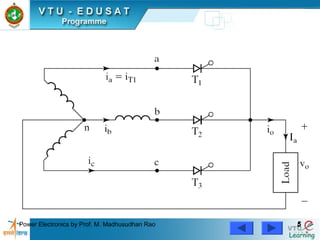
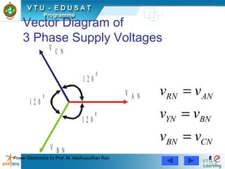
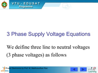
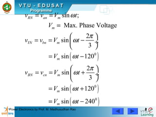
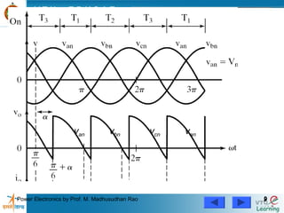
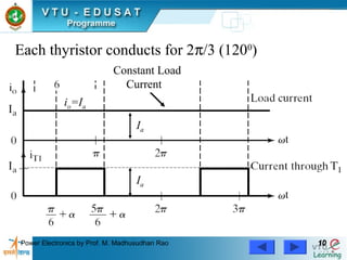
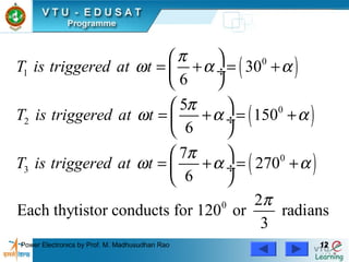
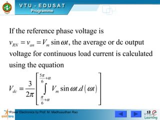
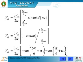
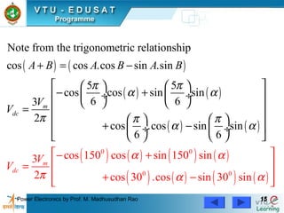
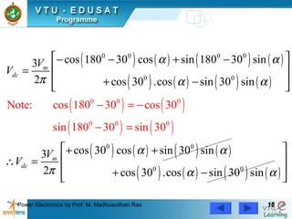
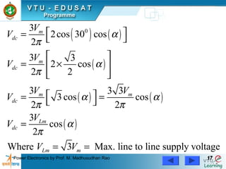
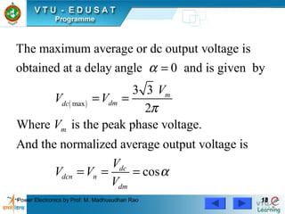
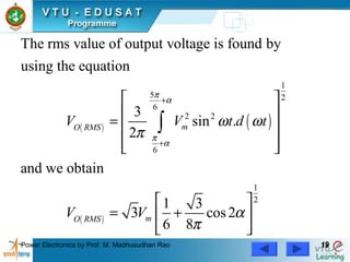
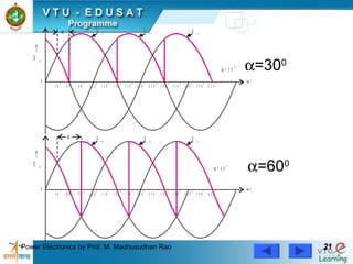
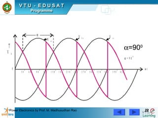
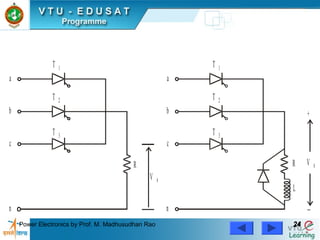
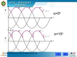
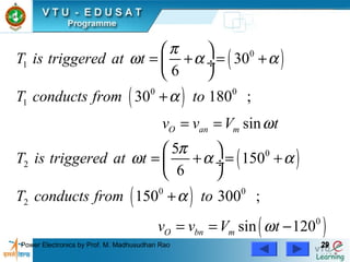
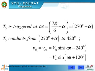
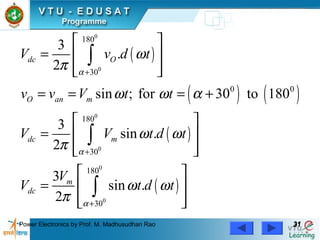
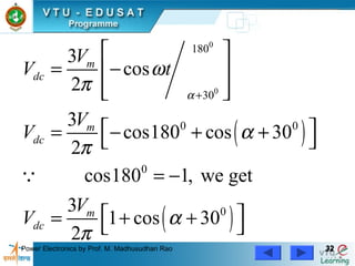
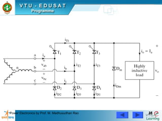
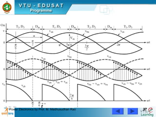
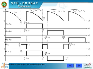
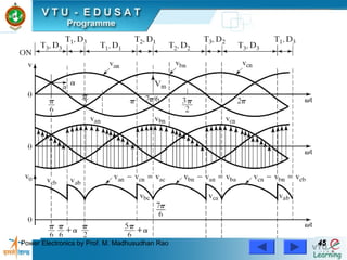
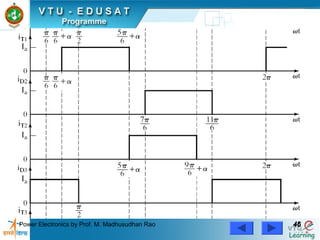
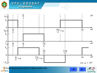
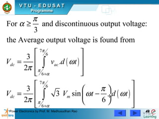
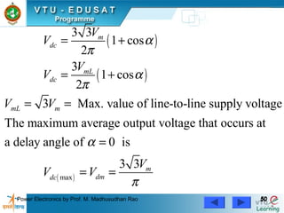
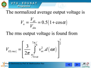
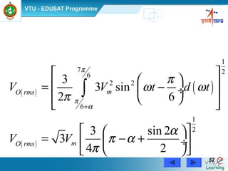
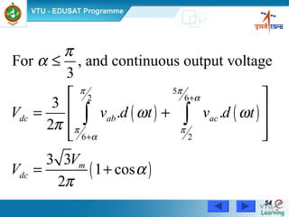
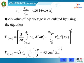
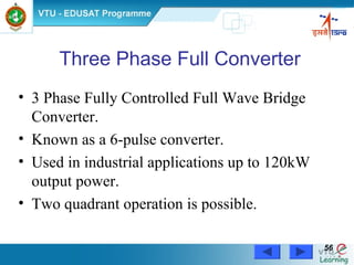
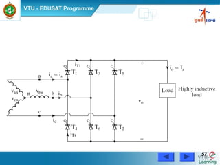
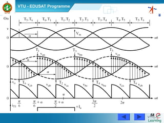
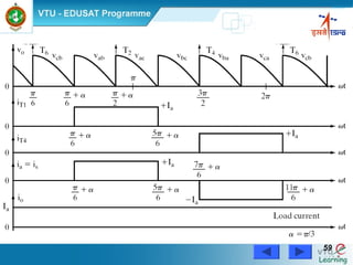
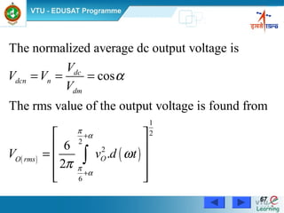
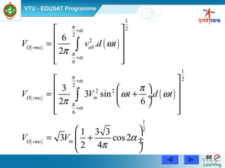
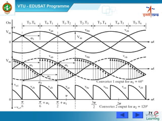
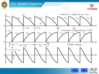
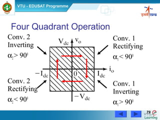
SlideShare a Scribd company logo
Power Electronics by Prof. M. Madhusudhan Rao 11
Three Phase Controlled
Rectifiers
Power Electronics by Prof. M. Madhusudhan Rao 22
3 Phase Controlled Rectifiers
• Operate from 3 phase ac supply voltage.
• They provide higher dc output voltage.
• Higher dc output power.
• Higher output voltage ripple frequency.
• Filtering requirements are simplified for
smoothing out load voltage and load current.
Power Electronics by Prof. M. Madhusudhan Rao 33
• Extensively used in high power variable speed
industrial dc drives.
• Three single phase half-wave converters can be
connected together to form a three phase half-
wave converter.
Power Electronics by Prof. M. Madhusudhan Rao 44
3-Phase
Half Wave Converter
(3-Pulse Converter)
with
RL Load
Continuous & Constant
Load Current Operation
Power Electronics by Prof. M. Madhusudhan Rao 55
Power Electronics by Prof. M. Madhusudhan Rao 66
Vector Diagram of
3 Phase Supply Voltages
V A N
V C N
V B N
1 2 0
0
1 2 0
0
1 2 0
0 RN AN
YN BN
BN CN
v v
v v
v v
=
=
=
Power Electronics by Prof. M. Madhusudhan Rao 77
3 Phase Supply Voltage Equations
We deifine three line to neutral voltages
(3 phase voltages) as follows
Power Electronics by Prof. M. Madhusudhan Rao 88
( )
( )
( )
0
0
0
sin ;
Max. Phase Voltage
2
sin
3
sin 120
2
sin
3
sin 120
sin 240
RN an m
m
YN bn m
m
BN cn m
m
m
v v V t
V
v v V t
V t
v v V t
V t
V t
ω
π
ω
ω
π
ω
ω
ω
= =
=
 
= = − ÷
 
= −
 
= = + ÷
 
= +
= −
Power Electronics by Prof. M. Madhusudhan Rao 99
van vbn vcn van
Power Electronics by Prof. M. Madhusudhan Rao 1010
io=Ia
Constant Load
Current
Ia
Ia
Each thyristor conducts for 2π/3 (1200
)
Power Electronics by Prof. M. Madhusudhan Rao 1111
To Derive an
Expression for the
Average Output Voltage of a
3-Phase Half Wave Converter
with RL Load
for Continuous Load Current
Power Electronics by Prof. M. Madhusudhan Rao 1212
( )
( )
( )
0
1
0
2
0
3
0
30
6
5
150
6
7
270
6
2
Each thytistor conducts for 120 or radians
3
T is triggered at t
T is triggered at t
T is triggered at t
π
ω α α
π
ω α α
π
ω α α
π
 
= + = + ÷
 
 
= + = + ÷
 
 
= + = + ÷
 
Power Electronics by Prof. M. Madhusudhan Rao 1313
( )
5
6
6
If the reference phase voltage is
sin , the average or dc output
voltage for continuous load current is calculated
using the equation
3
sin .
2
RN an m
dc m
v v V t
V V t d t
π
α
π
α
ω
ω ω
π
+
+
= =
 
 
=  
  
∫
Power Electronics by Prof. M. Madhusudhan Rao 1414
( )
( )
5
6
6
5
6
6
3
sin .
2
3
cos
2
3 5
cos cos
2 6 6
m
dc
m
dc
m
dc
V
V t d t
V
V t
V
V
π
α
π
α
π
α
π
α
ω ω
π
ω
π
π π
α α
π
+
+
+
+
 
 
=  
  
 
 
= − 
  
    
= − + + + ÷  ÷ 
    
∫
Power Electronics by Prof. M. Madhusudhan Rao 1515
( ) ( )
( ) ( )
( ) ( )
( ) ( ) ( ) ( )
( ) ( )
0 0
0
Note from the trigonometric relationship
cos cos .cos sin .sin
5 5
cos cos sin sin
6 63
2
co
cos 150 cos sin 150 sin3
2 cos 30
s .cos sin sin
6 6
.cos
m
dc
m
dc
A
V
V
B A B A B
V
V
π π
α α
π π π
α
α
α
α
π α
+ = −
    
− + ÷  ÷ 
    =
    
+ −  ÷  ÷
   
−
+

+
=
− ( ) ( )0
sin 30 sin α
 
 
 
 
Power Electronics by Prof. M. Madhusudhan Rao 1616
( ) ( ) ( ) ( )
( ) ( ) ( ) ( )
( ) ( )
( ) ( )
( ) ( ) ( ) ( )
( ) ( ) ( ) ( )
0 0
0 0 0 0
0 0
0 0
0
0
0
0
0 0
Note: cos 1
cos 180 30 cos sin 180 30 sin3
2 cos 30 .cos sin 30 sin
cos 30 cos sin 30 sin3
2 cos 30 .cos sin 30 s
80 30 cos 30
sin 180 30 sin 30
in
m
dc
m
dc
V
V
V
V
α α
π α α
α α
π α α
− =
 − − + −
 =
 + − 
 + +
 ∴ =
 + −
=

−
−
Power Electronics by Prof. M. Madhusudhan Rao 1717
( ) ( )
( )
( ) ( )
( )
03
2cos 30 cos
2
3 3
2 cos
2 2
3 3 3
3 cos cos
2 2
3
cos
2
Where 3 Max. line to line supply voltage
m
dc
m
dc
m m
dc
Lm
dc
Lm m
V
V
V
V
V V
V
V
V
V V
α
π
α
π
α α
π π
α
π
 =  
 
= × 
 
 = = 
=
= =
Power Electronics by Prof. M. Madhusudhan Rao 1818
( )max
The maximum average or dc output voltage is
obtained at a delay angle 0 and is given by
3 3
2
Where is the peak phase voltage.
And the normalized average output voltage is
m
dmdc
m
d
dcn n
V
V V
V
V
V V
α
π
=
= =
= = cosc
dmV
α=
Power Electronics by Prof. M. Madhusudhan Rao 1919
( ) ( )
( )
1
5 2
6
2 2
6
1
2
The rms value of output voltage is found by
using the equation
3
sin .
2
and we obtain
1 3
3 cos2
6 8
mO RMS
mO RMS
V V t d t
V V
π
α
π
α
ω ω
π
α
π
+
+
 
 
=  
  
 
= + 
 
∫
Power Electronics by Prof. M. Madhusudhan Rao 2020
3 Phase Half Wave
Controlled Rectifier Output Voltage
Waveforms For RL Load
at
Different Trigger Angles
Power Electronics by Prof. M. Madhusudhan Rao 2121
0
0
3 0
0
3 0
0
6 0
0
6 0
0
9 0
0
9 0
0
1 2 0
0
1 2 0
0
1 5 0
0
1 5 0
0
1 8 0
0
1 8 0
0
2 1 0
0
2 1 0
0
2 4 0
0
2 4 0
0
2 7 0
0
2 7 0
0
3 0 0
0
3 0 0
0
3 3 0
0
3 3 0
0
3 6 0
0
3 6 0
0
3 9 0
0
3 9 0
0
4 2 0
0
4 2 0
0
V a n
↑
V 0
↑
V 0
V a n
α
α
α = 3 0
0
α = 6 0
0
V b n
V b n
V c n
V c n
ω t
ω t
α=300
α=600
Power Electronics by Prof. M. Madhusudhan Rao 2222
0
3 0
0
6 0
0
9 0
0
1 2 0
0
1 5 0
0
1 8 0
0
2 1 0
0
2 4 0
0
2 7 0
0
3 0 0
0
3 3 0
0
3 6 0
0
3 9 0
0
4 2 0
0
↑
V 0
V a n
α
α = 9 0
0
V b n V c n
ω t
α=900
Power Electronics by Prof. M. Madhusudhan Rao 2323
3 Phase Half Wave
Controlled Rectifier With
R Load
and
RL Load with FWD
Power Electronics by Prof. M. Madhusudhan Rao 2424
a a
b b
c c
R
V 0
L
R V 0
+
−
T 1
T 2
T 3
n n
T 1
T 2
T 3
Power Electronics by Prof. M. Madhusudhan Rao 2525
3 Phase Half Wave
Controlled Rectifier Output Voltage
Waveforms For R Load
or RL Load with FWD
at
Different Trigger Angles
Power Electronics by Prof. M. Madhusudhan Rao 2626
0
0
3 0
0
3 0
0
6 0
0
6 0
0
9 0
0
9 0
0
1 2 0
0
1 2 0
0
1 5 0
0
1 5 0
0
1 8 0
0
1 8 0
0
2 1 0
0
2 1 0
0
2 4 0
0
2 4 0
0
2 7 0
0
2 7 0
0
3 0 0
0
3 0 0
0
3 3 0
0
3 3 0
0
3 6 0
0
3 6 0
0
3 9 0
0
3 9 0
0
4 2 0
0
4 2 0
0
V s
V 0
V a n
α
α = 0
α = 1 5 0
V b n V c n
ω t
V a n
V b n V c n
ω t
α=00
α=150
Power Electronics by Prof. M. Madhusudhan Rao 2727
0
0
3 0
0
3 0
0
6 0
0
6 0
0
9 0
0
9 0
0
1 2 0
0
1 2 0
0
1 5 0
0
1 5 0
0
1 8 0
0
1 8 0
0
2 1 0
0
2 1 0
0
2 4 0
0
2 4 0
0
2 7 0
0
2 7 0
0
3 0 0
0
3 0 0
0
3 3 0
0
3 3 0
0
3 6 0
0
3 6 0
0
3 9 0
0
3 9 0
0
4 2 0
0
4 2 0
0
α
α
V 0
α = 3 0
0
V a n
V b n V c n
ω t
V 0
α = 6 0
0
V a n
V b n V c n
ω t
α=300
α=600
Power Electronics by Prof. M. Madhusudhan Rao 2828
To Derive An
Expression For The Average Or
Dc Output Voltage Of A
3 Phase Half Wave Converter With
Resistive Load
Or
RL Load With FWD
Power Electronics by Prof. M. Madhusudhan Rao 2929
( )
( )
( )
( )
( )
0
1
0 0
1
0
2
0 0
2
0
30
6
30 180 ;
sin
5
150
6
150 300 ;
sin 120
O an m
O bn m
T is triggered at t
T conducts from to
v v V t
T is triggered at t
T conducts from to
v v V t
π
ω α α
α
ω
π
ω α α
α
ω
 
= + = + ÷
 
+
= =
 
= + = + ÷
 
+
= = −
Power Electronics by Prof. M. Madhusudhan Rao 3030
( )
( )
( )
( )
0
3
0 0
3
0
0
7
270
6
270 420 ;
sin 240
sin 120
O cn m
m
T is triggered at t
T conducts from to
v v V t
V t
π
ω α α
α
ω
ω
 
= + = + ÷
 
+
= = −
= +
Power Electronics by Prof. M. Madhusudhan Rao 3131
( )
( ) ( )
( )
( )
0
0
0
0
0
0
180
30
0 0
180
30
180
30
3
.
2
sin ; for 30 to 180
3
sin .
2
3
sin .
2
dc O
O an m
dc m
m
dc
V v d t
v v V t t
V V t d t
V
V t d t
α
α
α
ω
π
ω ω α
ω ω
π
ω ω
π
+
+
+
 
=  
  
= = = +
 
=  
  
 
=  
  
∫
∫
∫
Power Electronics by Prof. M. Madhusudhan Rao 3232
( )
( )
0
0
180
30
0 0
0
0
3
cos
2
3
cos180 cos 30
2
cos180 1, we get
3
1 cos 30
2
m
dc
m
dc
m
dc
V
V t
V
V
V
V
α
ω
π
α
π
α
π
+
 
= − 
  
 = − + + 
= −
 = + + 
Q
Power Electronics by Prof. M. Madhusudhan Rao 3333
Three Phase Semiconverters
• 3 Phase semiconverters are used in Industrial
dc drive applications upto 120kW power
output.
• Single quadrant operation is possible.
• Power factor decreases as the delay angle
increases.
• Power factor is better than that of 3 phase half
wave converter.
Power Electronics by Prof. M. Madhusudhan Rao 3434
3 Phase
Half Controlled Bridge Converter
(Semi Converter)
with Highly Inductive Load &
Continuous Ripple free Load Current
Power Electronics by Prof. M. Madhusudhan Rao 3535
Power Electronics by Prof. M. Madhusudhan Rao 3636
Wave forms of 3 Phase Semiconverter
for
α > 600
Power Electronics by Prof. M. Madhusudhan Rao 3737
Power Electronics by Prof. M. Madhusudhan Rao 3838
Power Electronics by Prof. M. Madhusudhan Rao 3939
0 0
1
3 phase semiconverter output ripple frequency of
output voltage is 3
The delay angle can be varied from 0 to
During the period
30 210
7
, thyristor T is forward biased
6 6
Sf
t
t
α π
ω
π π
ω
≤ <
≤ <
Power Electronics by Prof. M. Madhusudhan Rao 4040
1
1 1
If thyristor is triggered at ,
6
& conduct together and the line to line voltage
appears across the load.
7
At , becomes negative & FWD conducts.
6
The load current contin
ac
ac m
T t
T D
v
t v D
π
ω α
π
ω
 
= + ÷
 
=
1 1
ues to flow through FWD ;
and are turned off.
mD
T D
Power Electronics by Prof. M. Madhusudhan Rao 4141
1
2
1 2
If FWD is not used the would continue to
conduct until the thyristor is triggered at
5
, and Free wheeling action would
6
be accomplished through & .
If the delay angle , e
3
mD T
T
t
T D
π
ω α
π
α
 
= + ÷
 
≤ ach thyristor conducts
2
for and the FWD does not conduct.
3
mD
π
Power Electronics by Prof. M. Madhusudhan Rao 4242
( )
( )
( )
0
0
0
We deifine three line neutral voltages
(3 phase voltages) as follows
sin ; Max. Phase Voltage
2
sin sin 120
3
2
sin sin 120
3
sin 240
RN an m m
YN bn m m
BN cn m m
m
v v V t V
v v V t V t
v v V t V t
V t
V
ω
π
ω ω
π
ω ω
ω
= = =
 
= = − = − ÷
 
 
= = + = + ÷
 
= −
is the peak phase voltage of a wye-connected sourcem
Power Electronics by Prof. M. Madhusudhan Rao 4343
( )
( )
( )
( )
3 sin
6
5
3 sin
6
3 sin
2
3 sin
6
RB ac an cn m
YR ba bn an m
BY cb cn bn m
RY ab an bn m
v v v v V t
v v v v V t
v v v v V t
v v v v V t
π
ω
π
ω
π
ω
π
ω
 
= = − = − ÷
 
 
= = − = − ÷
 
 
= = − = + ÷
 
 
= = − = + ÷
 
Power Electronics by Prof. M. Madhusudhan Rao 4444
Wave forms of 3 Phase Semiconverter
for
α ≤ 600
Power Electronics by Prof. M. Madhusudhan Rao 4545
Power Electronics by Prof. M. Madhusudhan Rao 4646
Power Electronics by Prof. M. Madhusudhan Rao 4747
Power Electronics by Prof. M. Madhusudhan Rao 4848
To derive an
Expression for the
Average Output Voltage
of 3 Phase Semiconverter
for α > π / 3
and Discontinuous Output Voltage
Power Electronics by Prof. M. Madhusudhan Rao 4949
( )
( )
7
6
6
7
6
6
For and discontinuous output voltage:
3
the Average output voltage is found from
3
.
2
3
3 sin
2 6
dc ac
dc m
V v d t
V V t d t
π
π
α
π
π
α
π
α
ω
π
π
ω ω
π
+
+
≥
 
 =
 
 
 
  = − ÷
  
 
∫
∫
Power Electronics by Prof. M. Madhusudhan Rao 5050
( )
( )
( )max
3 3
1 cos
2
3
1 cos
2
3 Max. value of line-to-line supply voltage
The maximum average output voltage that occurs at
a delay angle of 0 is
3 3
m
dc
mL
dc
mL m
m
dmdc
V
V
V
V
V V
V
V V
α
π
α
π
α
π
= +
= +
= =
=
= =
Power Electronics by Prof. M. Madhusudhan Rao 5151
( )
( ) ( )
1
7 26
2
6
The normalized average output voltage is
0.5 1 cos
The rms output voltage is found from
3
.
2
dc
n
dm
acO rms
V
V
V
V v d t
π
π
α
α
ω
π
+
= = +
 
 =
 
 
∫
Power Electronics by Prof. M. Madhusudhan Rao 5252
( ) ( )
( )
1
7 26
2 2
6
1
2
3
3 sin
2 6
3 sin 2
3
4 2
mO rms
mO rms
V V t d t
V V
π
π
α
π
ω ω
π
α
π α
π
+
 
  = − ÷
  
 
  
= − + ÷ 
  
∫
Power Electronics by Prof. M. Madhusudhan Rao 5353
Average or DC Output Voltage
of a
3-Phase Semiconverter
for α≤π / 3,
and Continuous Output Voltage
Power Electronics by Prof. M. Madhusudhan Rao 5454
( ) ( )
( )
5
62
6 2
For , and continuous output voltage
3
3
. .
2
3 3
1 cos
2
dc ab ac
m
dc
V v d t v d t
V
V
ππ
α
π π
α
π
α
ω ω
π
α
π
+
+
≤
 
 = +
 
 
= +
∫ ∫
Power Electronics by Prof. M. Madhusudhan Rao 5555
( )
( ) ( ) ( )
( )
1
5 262
2 2
6 2
1
2
2
0.5 1 cos
RMS value of o/p voltage is calculated by using
the equation
3
. .
2
3 2
3 3 cos
4 3
dc
n
dm
ab acO rms
mO rms
V
V
V
V v d t v d t
V V
ππ
α
π π
α
α
ω ω
π
π
α
π
+
+
= = +
 
 = +
 
 
  
= + ÷ 
  
∫ ∫
Power Electronics by Prof. M. Madhusudhan Rao 5656
Three Phase Full Converter
• 3 Phase Fully Controlled Full Wave Bridge
Converter.
• Known as a 6-pulse converter.
• Used in industrial applications up to 120kW
output power.
• Two quadrant operation is possible.
Power Electronics by Prof. M. Madhusudhan Rao 5757
Power Electronics by Prof. M. Madhusudhan Rao 5858
Power Electronics by Prof. M. Madhusudhan Rao 5959
Power Electronics by Prof. M. Madhusudhan Rao 6060
• The thyristors are triggered at an interval of
π / 3.
• The frequency of output ripple voltage is 6fS.
• T1 is triggered at ωt = (π/6 + α), T6 is already
conducting when T1 is turned ON.
• During the interval (π/6 + α) to (π/2 + α),
T1 and T6 conduct together & the output load
voltage is equal to vab= (van– vbn)
Power Electronics by Prof. M. Madhusudhan Rao 6161
• T2 is triggered at ωt = (π/2 + α), T6 turns off
naturally as it is reverse biased as soon as T2 is
triggered.
• During the interval (π/2 + α) to (5π/6 + α), T1
and T2 conduct together & the output load
voltage vO = vac = (van – vcn)
• Thyristors are numbered in the order in which
they are triggered.
• The thyristor triggering sequence is 12, 23,
34, 45, 56, 61, 12, 23, 34, ………
Power Electronics by Prof. M. Madhusudhan Rao 6262
( )
( )
( )
0
0
0
We deifine three line neutral voltages
(3 phase voltages) as follows
sin ; Max. Phase Voltage
2
sin sin 120
3
2
sin sin 120
3
sin 240
RN an m m
YN bn m m
BN cn m m
m
v v V t V
v v V t V t
v v V t V t
V t
V
ω
π
ω ω
π
ω ω
ω
= = =
 
= = − = − ÷
 
 
= = + = + ÷
 
= −
is the peak phase voltage of a wye-connected sourcem
Power Electronics by Prof. M. Madhusudhan Rao 6363
( )
( )
( )
The corresponding line-to-line
supply voltages are
3 sin
6
3 sin
2
3 sin
2
RY ab an bn m
YB bc bn cn m
BR ca cn an m
v v v v V t
v v v v V t
v v v v V t
π
ω
π
ω
π
ω
 
= = − = + ÷
 
 
= = − = − ÷
 
 
= = − = + ÷
 
Power Electronics by Prof. M. Madhusudhan Rao 6464
To Derive An Expression For The
Average Output Voltage Of
3-phase Full Converter
With Highly Inductive Load
Assuming Continuous And
Constant Load Current
Power Electronics by Prof. M. Madhusudhan Rao 6565
( )
2
6
6
. ;
2
3 sin
6
dc OO dc
O ab m
V V v d t
v v V t
π
α
π
α
ω
π
π
ω
+
+
= =
 
= = + ÷
 
∫
The output load voltage consists of 6 voltage
pulses over a period of 2π radians, Hence the
average output voltage is calculated as
Power Electronics by Prof. M. Madhusudhan Rao 6666
( )
2
6
mL
max
3
3 sin .
6
3 3 3
cos cos
Where V 3 Max. line-to-line supply vo
The maximum average dc output voltage is
obtained for a delay angle
ltage
3 3
0,
3
dc m
m mL
dc
m
m m
dmdc
V V t d t
V V
V
V
V V
V V
π
α
π
α
π
ω ω
π
α α
π
α
π
π
+
+
 
= + ÷
 
= =
=
=
=
= = =
∫
L
π
Power Electronics by Prof. M. Madhusudhan Rao 6767
( ) ( )
1
2
2
2
6
The normalized average dc output voltage is
cos
The rms value of the output voltage is found from
6
.
2
dc
dcn n
dm
OO rms
V
V V
V
V v d t
π
α
π
α
α
ω
π
+
+
= = =
 
 
=  
  
∫
Power Electronics by Prof. M. Madhusudhan Rao 6868
( ) ( )
( ) ( )
( )
1
2
2
2
6
1
2
2
2 2
6
1
2
6
.
2
3
3 sin .
2 6
1 3 3
3 cos2
2 4
abO rms
mO rms
mO rms
V v d t
V V t d t
V V
π
α
π
α
π
α
π
α
ω
π
π
ω ω
π
α
π
+
+
+
+
 
 
=  
  
 
  
= + ÷  
  
 
= + ÷ ÷
 
∫
∫
Power Electronics by Prof. M. Madhusudhan Rao 6969
Three Phase Dual Converters
• For four quadrant operation in many industrial
variable speed dc drives , 3 phase dual
converters are used.
• Used for applications up to 2 mega watt output
power level.
• Dual converter consists of two 3 phase full
converters which are connected in parallel & in
opposite directions across a common load.
Power Electronics by Prof. M. Madhusudhan Rao 7070
Power Electronics by Prof. M. Madhusudhan Rao 7171
Power Electronics by Prof. M. Madhusudhan Rao 7272
Power Electronics by Prof. M. Madhusudhan Rao 7373
Outputs of Converters 1 & 2
• During the interval (π/6 + α1) to (π/2 + α1), the
line to line voltage vab appears across the output
of converter 1 and vbc appears across the output
of converter 2
Power Electronics by Prof. M. Madhusudhan Rao 7474
( )
( )
( )
0
0
0
We deifine three line neutral voltages
(3 phase voltages) as follows
sin ;
Max. Phase Voltage
2
sin sin 120
3
2
sin sin 120
3
sin 240
RN an m
m
YN bn m m
BN cn m m
m
v v V t
V
v v V t V t
v v V t V t
V t
ω
π
ω ω
π
ω ω
ω
= =
=
 
= = − = − ÷
 
 
= = + = + ÷
 
= −
Power Electronics by Prof. M. Madhusudhan Rao 7575
( )
( )
( )
The corresponding line-to-line
supply voltages are
3 sin
6
3 sin
2
3 sin
2
RY ab an bn m
YB bc bn cn m
BR ca cn an m
v v v v V t
v v v v V t
v v v v V t
π
ω
π
ω
π
ω
 
= = − = + ÷
 
 
= = − = − ÷
 
 
= = − = + ÷
 
Power Electronics by Prof. M. Madhusudhan Rao 7676
• If vO1 and vO2 are the output voltages of
converters 1 and 2 respectively, the
instantaneous voltage across the current
limiting inductor during the interval
(π/6 + α1) ≤ ωt ≤ (π/2 + α1) is given by
To obtain an Expression for the
Circulating Current
Power Electronics by Prof. M. Madhusudhan Rao 7777
1 2
3 sin sin
6 2
3 cos
6
The circulating current can be calculated by
using the equation
r O O ab bc
r m
r m
v v v v v
v V t t
v V t
π π
ω ω
π
ω
= + = −
    
= + − − ÷  ÷ 
    
 
= − ÷
 
Power Electronics by Prof. M. Madhusudhan Rao 7878
( ) ( )
( ) ( )
( )
( )
1
1
6
6
1
max
1
.
1
3 cos .
6
3
sin sin
6
3
t
r r
r
t
r m
r
m
r
r
m
r
r
i t v d t
L
i t V t d t
L
V
i t t
L
V
i
L
ω
π
α
ω
π
α
ω
ω
π
ω ω
ω
π
ω α
ω
ω
+
+
=
 
= − ÷
 
  
= − − ÷ 
  
=
∫
∫
Power Electronics by Prof. M. Madhusudhan Rao 7979
Four Quadrant Operation
Conv. 2
Inverting
α2> 900
Conv. 2
Rectifying
α2< 900
Conv. 1
Rectifying
α1< 900
Conv. 1
Inverting
α1> 900
Power Electronics by Prof. M. Madhusudhan Rao 8080
• There are two different modes of operation.
 Circulating current free
(non circulating) mode of operation
 Circulating current mode of operation
Power Electronics by Prof. M. Madhusudhan Rao 8181
Non Circulating
Current Mode Of Operation
• In this mode of operation only one converter is
switched on at a time
• When the converter 1 is switched on,
For α1 < 900
the converter 1 operates in the
Rectification mode
Vdc is positive, Idc is positive and hence the
average load power Pdc is positive.
• Power flows from ac source to the load
Power Electronics by Prof. M. Madhusudhan Rao 8282
• When the converter 1 is on,
For α1 > 900
the converter 1 operates in the
Inversion mode
Vdc is negative, Idc is positive and the average
load power Pdc is negative.
• Power flows from load circuit to ac source.
Power Electronics by Prof. M. Madhusudhan Rao 8383
• When the converter 2 is switched on,
For α2 < 900
the converter 2 operates in the
Rectification mode
Vdc is negative, Idc is negative and the average
load power Pdc is positive.
• The output load voltage & load current reverse
when converter 2 is on.
• Power flows from ac source to the load
Power Electronics by Prof. M. Madhusudhan Rao 8484
• When the converter 2 is switched on,
For α2 > 900
the converter 2 operates in the
Inversion mode
Vdc is positive, Idc is negative and the average
load power Pdc is negative.
• Power flows from load to the ac source.
• Energy is supplied from the load circuit to the
ac supply.
Power Electronics by Prof. M. Madhusudhan Rao 8585
Circulating Current
Mode Of Operation
• Both the converters are switched on at the
same time.
• One converter operates in the rectification
mode while the other operates in the inversion
mode.
• Trigger angles α1 & α2 are adjusted such that
(α1 + α2) = 1800
Power Electronics by Prof. M. Madhusudhan Rao 8686
• When α1 < 900
, converter 1 operates as a
controlled rectifier. α2 is made greater than 900
and converter 2 operates as an Inverter.
• Vdc is positive & Idc is positive and Pdc is positive.
Power Electronics by Prof. M. Madhusudhan Rao 8787
• When α2 < 900
, converter 2 operates as a
controlled rectifier. α1 is made greater than 900
and converter 1 operates as an Inverter.
• Vdc is negative & Idc is negative and Pdc is
positive.

More Related Content

What's hot

Power flow solution
Power flow solutionPower flow solution
Power flow solution
Balaram Das
 
GENERATING OF HIGH ALTERNATING VOLTAGE
GENERATING OF HIGH ALTERNATING VOLTAGEGENERATING OF HIGH ALTERNATING VOLTAGE
GENERATING OF HIGH ALTERNATING VOLTAGE
Jamil Abdullah
 
Generation of High D.C. Voltage (HVDC generation)
Generation of High D.C. Voltage (HVDC generation)Generation of High D.C. Voltage (HVDC generation)
Generation of High D.C. Voltage (HVDC generation)
RP6997
 
Symmetrical components
Symmetrical componentsSymmetrical components
Symmetrical components
Sirat Mahmood
 
Unit iv-inverters-new
Unit iv-inverters-newUnit iv-inverters-new
Unit iv-inverters-new
Sakthivel Ganesan
 
Dual and cyclo converter
Dual and cyclo converterDual and cyclo converter
Dual and cyclo converter
Rutika Abhang
 
Three phase transformer ( vector groups)
Three phase  transformer ( vector groups)Three phase  transformer ( vector groups)
Three phase transformer ( vector groups)
Dr.Raja Masood Larik
 
Sssc
SsscSssc
A presentation on inverter by manoj
A presentation on inverter by manojA presentation on inverter by manoj
A presentation on inverter by manoj
IACM SmartLearn Ltd.
 
Single phase ac voltage controller
Single phase ac voltage controllerSingle phase ac voltage controller
Single phase ac voltage controller
Swati Tiwari
 
Lecture 10
Lecture 10Lecture 10
Lecture 10
Forward2025
 
Chopper operation
Chopper  operationChopper  operation
Chopper operation
vishalgohel12195
 
1 ph semi converter (r-l load)
1 ph semi converter (r-l load)1 ph semi converter (r-l load)
1 ph semi converter (r-l load)avi1001
 
Synchronous generator
Synchronous generatorSynchronous generator
Synchronous generator
Power System Operation
 
Transmission lines
Transmission linesTransmission lines
Transmission lines
Zulfiqar Mangrio
 
Power electronics Phase Controlled Rectifiers - SCR
Power electronics   Phase Controlled Rectifiers - SCRPower electronics   Phase Controlled Rectifiers - SCR
Power electronics Phase Controlled Rectifiers - SCR
Burdwan University
 
Fault analysis
Fault analysisFault analysis
Fault analysis
Revathi Subramaniam
 
Power Electronics lab manual BE EEE
Power Electronics lab manual BE EEEPower Electronics lab manual BE EEE
Power Electronics lab manual BE EEE
Dr M Muruganandam Masilamani
 
Switchgear and protection 1
Switchgear and protection 1Switchgear and protection 1
Switchgear and protection 1
Md Irshad Ahmad
 
Controlled Rectifier
Controlled RectifierControlled Rectifier
Controlled Rectifier
Faraz Ahmed
 

What's hot (20)

Power flow solution
Power flow solutionPower flow solution
Power flow solution
 
GENERATING OF HIGH ALTERNATING VOLTAGE
GENERATING OF HIGH ALTERNATING VOLTAGEGENERATING OF HIGH ALTERNATING VOLTAGE
GENERATING OF HIGH ALTERNATING VOLTAGE
 
Generation of High D.C. Voltage (HVDC generation)
Generation of High D.C. Voltage (HVDC generation)Generation of High D.C. Voltage (HVDC generation)
Generation of High D.C. Voltage (HVDC generation)
 
Symmetrical components
Symmetrical componentsSymmetrical components
Symmetrical components
 
Unit iv-inverters-new
Unit iv-inverters-newUnit iv-inverters-new
Unit iv-inverters-new
 
Dual and cyclo converter
Dual and cyclo converterDual and cyclo converter
Dual and cyclo converter
 
Three phase transformer ( vector groups)
Three phase  transformer ( vector groups)Three phase  transformer ( vector groups)
Three phase transformer ( vector groups)
 
Sssc
SsscSssc
Sssc
 
A presentation on inverter by manoj
A presentation on inverter by manojA presentation on inverter by manoj
A presentation on inverter by manoj
 
Single phase ac voltage controller
Single phase ac voltage controllerSingle phase ac voltage controller
Single phase ac voltage controller
 
Lecture 10
Lecture 10Lecture 10
Lecture 10
 
Chopper operation
Chopper  operationChopper  operation
Chopper operation
 
1 ph semi converter (r-l load)
1 ph semi converter (r-l load)1 ph semi converter (r-l load)
1 ph semi converter (r-l load)
 
Synchronous generator
Synchronous generatorSynchronous generator
Synchronous generator
 
Transmission lines
Transmission linesTransmission lines
Transmission lines
 
Power electronics Phase Controlled Rectifiers - SCR
Power electronics   Phase Controlled Rectifiers - SCRPower electronics   Phase Controlled Rectifiers - SCR
Power electronics Phase Controlled Rectifiers - SCR
 
Fault analysis
Fault analysisFault analysis
Fault analysis
 
Power Electronics lab manual BE EEE
Power Electronics lab manual BE EEEPower Electronics lab manual BE EEE
Power Electronics lab manual BE EEE
 
Switchgear and protection 1
Switchgear and protection 1Switchgear and protection 1
Switchgear and protection 1
 
Controlled Rectifier
Controlled RectifierControlled Rectifier
Controlled Rectifier
 

Similar to Three phase-controlled-rectifiers

Unit-2 Three Phase controlled converter
Unit-2 Three Phase controlled converter Unit-2 Three Phase controlled converter
Unit-2 Three Phase controlled converter
johny renoald
 
U_1.ppt
U_1.pptU_1.ppt
U_1.ppt
AparnaPrayag
 
Three Phase Rectifier By Vivek Ahlawat
Three Phase Rectifier By Vivek AhlawatThree Phase Rectifier By Vivek Ahlawat
Three Phase Rectifier By Vivek Ahlawat
VIVEK AHLAWAT
 
analisa sistem tenaga lanjut
analisa sistem tenaga lanjutanalisa sistem tenaga lanjut
analisa sistem tenaga lanjut
suparman unkhair
 
Per unit analysis
Per unit analysisPer unit analysis
Per unit analysis
Revathi Subramaniam
 
Power Electronics fundamentals for the Engineerng
Power Electronics fundamentals for the EngineerngPower Electronics fundamentals for the Engineerng
Power Electronics fundamentals for the Engineerng
balakrishnakece
 
Network analysis unit 2
Network analysis unit 2Network analysis unit 2
Network analysis unit 2
sai divya sri sappa
 
Converters
ConvertersConverters
Converters
asprilla mangombe
 
Power Circuits and Transforers-Unit 6 Labvolt Student Manual
Power Circuits and Transforers-Unit 6 Labvolt Student ManualPower Circuits and Transforers-Unit 6 Labvolt Student Manual
Power Circuits and Transforers-Unit 6 Labvolt Student Manual
phase3-120A
 
Dc Choppers
Dc ChoppersDc Choppers
Dc Choppersstooty s
 
7- 1st semester_BJT_AC_Analysis (re model)-1.pdf
7- 1st semester_BJT_AC_Analysis (re model)-1.pdf7- 1st semester_BJT_AC_Analysis (re model)-1.pdf
7- 1st semester_BJT_AC_Analysis (re model)-1.pdf
ssuserfefa63
 
L21- Three Phase Excitation _ reprentation.pptx
L21- Three Phase  Excitation _ reprentation.pptxL21- Three Phase  Excitation _ reprentation.pptx
L21- Three Phase Excitation _ reprentation.pptx
happycocoman
 
VTU Basic electrical Lab manual
VTU Basic electrical Lab manualVTU Basic electrical Lab manual
VTU Basic electrical Lab manual
Prashanth Krushi
 
Basic Electrical Engineering Lab Manual 2018 cbcs scheme VTU
 Basic Electrical Engineering Lab Manual 2018 cbcs scheme VTU Basic Electrical Engineering Lab Manual 2018 cbcs scheme VTU
Basic Electrical Engineering Lab Manual 2018 cbcs scheme VTU
Prashanth Krushi
 
B1103021427
B1103021427B1103021427
B1103021427
IOSR Journals
 
Basic electrical lab manual 2018 scheme
Basic electrical lab manual 2018 schemeBasic electrical lab manual 2018 scheme
Basic electrical lab manual 2018 scheme
Prashanth Krushi
 
Per unit calculation
Per unit calculationPer unit calculation
Per unit calculation
obaidurbd
 
Eet3082 binod kumar sahu lecture_35
Eet3082 binod kumar sahu lecture_35Eet3082 binod kumar sahu lecture_35
Eet3082 binod kumar sahu lecture_35
BinodKumarSahu5
 

Similar to Three phase-controlled-rectifiers (20)

Unit-2 Three Phase controlled converter
Unit-2 Three Phase controlled converter Unit-2 Three Phase controlled converter
Unit-2 Three Phase controlled converter
 
U_1.ppt
U_1.pptU_1.ppt
U_1.ppt
 
Three Phase Rectifier By Vivek Ahlawat
Three Phase Rectifier By Vivek AhlawatThree Phase Rectifier By Vivek Ahlawat
Three Phase Rectifier By Vivek Ahlawat
 
analisa sistem tenaga lanjut
analisa sistem tenaga lanjutanalisa sistem tenaga lanjut
analisa sistem tenaga lanjut
 
Per unit analysis
Per unit analysisPer unit analysis
Per unit analysis
 
Power Electronics fundamentals for the Engineerng
Power Electronics fundamentals for the EngineerngPower Electronics fundamentals for the Engineerng
Power Electronics fundamentals for the Engineerng
 
Network analysis unit 2
Network analysis unit 2Network analysis unit 2
Network analysis unit 2
 
Converters
ConvertersConverters
Converters
 
Power Circuits and Transforers-Unit 6 Labvolt Student Manual
Power Circuits and Transforers-Unit 6 Labvolt Student ManualPower Circuits and Transforers-Unit 6 Labvolt Student Manual
Power Circuits and Transforers-Unit 6 Labvolt Student Manual
 
Dc Choppers
Dc ChoppersDc Choppers
Dc Choppers
 
7- 1st semester_BJT_AC_Analysis (re model)-1.pdf
7- 1st semester_BJT_AC_Analysis (re model)-1.pdf7- 1st semester_BJT_AC_Analysis (re model)-1.pdf
7- 1st semester_BJT_AC_Analysis (re model)-1.pdf
 
1 7
1 71 7
1 7
 
L21- Three Phase Excitation _ reprentation.pptx
L21- Three Phase  Excitation _ reprentation.pptxL21- Three Phase  Excitation _ reprentation.pptx
L21- Three Phase Excitation _ reprentation.pptx
 
VTU Basic electrical Lab manual
VTU Basic electrical Lab manualVTU Basic electrical Lab manual
VTU Basic electrical Lab manual
 
Basic Electrical Engineering Lab Manual 2018 cbcs scheme VTU
 Basic Electrical Engineering Lab Manual 2018 cbcs scheme VTU Basic Electrical Engineering Lab Manual 2018 cbcs scheme VTU
Basic Electrical Engineering Lab Manual 2018 cbcs scheme VTU
 
B1103021427
B1103021427B1103021427
B1103021427
 
Basic electrical lab manual 2018 scheme
Basic electrical lab manual 2018 schemeBasic electrical lab manual 2018 scheme
Basic electrical lab manual 2018 scheme
 
Per unit calculation
Per unit calculationPer unit calculation
Per unit calculation
 
Eet3082 binod kumar sahu lecture_35
Eet3082 binod kumar sahu lecture_35Eet3082 binod kumar sahu lecture_35
Eet3082 binod kumar sahu lecture_35
 
1 7
1 71 7
1 7
 

Recently uploaded

BASIC C++ lecture NOTE C++ lecture 3.pptx
BASIC C++ lecture NOTE C++ lecture 3.pptxBASIC C++ lecture NOTE C++ lecture 3.pptx
BASIC C++ lecture NOTE C++ lecture 3.pptx
natyesu
 
1.Wireless Communication System_Wireless communication is a broad term that i...
1.Wireless Communication System_Wireless communication is a broad term that i...1.Wireless Communication System_Wireless communication is a broad term that i...
1.Wireless Communication System_Wireless communication is a broad term that i...
JeyaPerumal1
 
Living-in-IT-era-Module-7-Imaging-and-Design-for-Social-Impact.pptx
Living-in-IT-era-Module-7-Imaging-and-Design-for-Social-Impact.pptxLiving-in-IT-era-Module-7-Imaging-and-Design-for-Social-Impact.pptx
Living-in-IT-era-Module-7-Imaging-and-Design-for-Social-Impact.pptx
TristanJasperRamos
 
Output determination SAP S4 HANA SAP SD CC
Output determination SAP S4 HANA SAP SD CCOutput determination SAP S4 HANA SAP SD CC
Output determination SAP S4 HANA SAP SD CC
ShahulHameed54211
 
The+Prospects+of+E-Commerce+in+China.pptx
The+Prospects+of+E-Commerce+in+China.pptxThe+Prospects+of+E-Commerce+in+China.pptx
The+Prospects+of+E-Commerce+in+China.pptx
laozhuseo02
 
History+of+E-commerce+Development+in+China-www.cfye-commerce.shop
History+of+E-commerce+Development+in+China-www.cfye-commerce.shopHistory+of+E-commerce+Development+in+China-www.cfye-commerce.shop
History+of+E-commerce+Development+in+China-www.cfye-commerce.shop
laozhuseo02
 
原版仿制(uob毕业证书)英国伯明翰大学毕业证本科学历证书原版一模一样
原版仿制(uob毕业证书)英国伯明翰大学毕业证本科学历证书原版一模一样原版仿制(uob毕业证书)英国伯明翰大学毕业证本科学历证书原版一模一样
原版仿制(uob毕业证书)英国伯明翰大学毕业证本科学历证书原版一模一样
3ipehhoa
 
This 7-second Brain Wave Ritual Attracts Money To You.!
This 7-second Brain Wave Ritual Attracts Money To You.!This 7-second Brain Wave Ritual Attracts Money To You.!
This 7-second Brain Wave Ritual Attracts Money To You.!
nirahealhty
 
Multi-cluster Kubernetes Networking- Patterns, Projects and Guidelines
Multi-cluster Kubernetes Networking- Patterns, Projects and GuidelinesMulti-cluster Kubernetes Networking- Patterns, Projects and Guidelines
Multi-cluster Kubernetes Networking- Patterns, Projects and Guidelines
Sanjeev Rampal
 
Latest trends in computer networking.pptx
Latest trends in computer networking.pptxLatest trends in computer networking.pptx
Latest trends in computer networking.pptx
JungkooksNonexistent
 
guildmasters guide to ravnica Dungeons & Dragons 5...
guildmasters guide to ravnica Dungeons & Dragons 5...guildmasters guide to ravnica Dungeons & Dragons 5...
guildmasters guide to ravnica Dungeons & Dragons 5...
Rogerio Filho
 
test test test test testtest test testtest test testtest test testtest test ...
test test  test test testtest test testtest test testtest test testtest test ...test test  test test testtest test testtest test testtest test testtest test ...
test test test test testtest test testtest test testtest test testtest test ...
Arif0071
 
ER(Entity Relationship) Diagram for online shopping - TAE
ER(Entity Relationship) Diagram for online shopping - TAEER(Entity Relationship) Diagram for online shopping - TAE
ER(Entity Relationship) Diagram for online shopping - TAE
Himani415946
 
急速办(bedfordhire毕业证书)英国贝德福特大学毕业证成绩单原版一模一样
急速办(bedfordhire毕业证书)英国贝德福特大学毕业证成绩单原版一模一样急速办(bedfordhire毕业证书)英国贝德福特大学毕业证成绩单原版一模一样
急速办(bedfordhire毕业证书)英国贝德福特大学毕业证成绩单原版一模一样
3ipehhoa
 
How to Use Contact Form 7 Like a Pro.pptx
How to Use Contact Form 7 Like a Pro.pptxHow to Use Contact Form 7 Like a Pro.pptx
How to Use Contact Form 7 Like a Pro.pptx
Gal Baras
 
1比1复刻(bath毕业证书)英国巴斯大学毕业证学位证原版一模一样
1比1复刻(bath毕业证书)英国巴斯大学毕业证学位证原版一模一样1比1复刻(bath毕业证书)英国巴斯大学毕业证学位证原版一模一样
1比1复刻(bath毕业证书)英国巴斯大学毕业证学位证原版一模一样
3ipehhoa
 

Recently uploaded (16)

BASIC C++ lecture NOTE C++ lecture 3.pptx
BASIC C++ lecture NOTE C++ lecture 3.pptxBASIC C++ lecture NOTE C++ lecture 3.pptx
BASIC C++ lecture NOTE C++ lecture 3.pptx
 
1.Wireless Communication System_Wireless communication is a broad term that i...
1.Wireless Communication System_Wireless communication is a broad term that i...1.Wireless Communication System_Wireless communication is a broad term that i...
1.Wireless Communication System_Wireless communication is a broad term that i...
 
Living-in-IT-era-Module-7-Imaging-and-Design-for-Social-Impact.pptx
Living-in-IT-era-Module-7-Imaging-and-Design-for-Social-Impact.pptxLiving-in-IT-era-Module-7-Imaging-and-Design-for-Social-Impact.pptx
Living-in-IT-era-Module-7-Imaging-and-Design-for-Social-Impact.pptx
 
Output determination SAP S4 HANA SAP SD CC
Output determination SAP S4 HANA SAP SD CCOutput determination SAP S4 HANA SAP SD CC
Output determination SAP S4 HANA SAP SD CC
 
The+Prospects+of+E-Commerce+in+China.pptx
The+Prospects+of+E-Commerce+in+China.pptxThe+Prospects+of+E-Commerce+in+China.pptx
The+Prospects+of+E-Commerce+in+China.pptx
 
History+of+E-commerce+Development+in+China-www.cfye-commerce.shop
History+of+E-commerce+Development+in+China-www.cfye-commerce.shopHistory+of+E-commerce+Development+in+China-www.cfye-commerce.shop
History+of+E-commerce+Development+in+China-www.cfye-commerce.shop
 
原版仿制(uob毕业证书)英国伯明翰大学毕业证本科学历证书原版一模一样
原版仿制(uob毕业证书)英国伯明翰大学毕业证本科学历证书原版一模一样原版仿制(uob毕业证书)英国伯明翰大学毕业证本科学历证书原版一模一样
原版仿制(uob毕业证书)英国伯明翰大学毕业证本科学历证书原版一模一样
 
This 7-second Brain Wave Ritual Attracts Money To You.!
This 7-second Brain Wave Ritual Attracts Money To You.!This 7-second Brain Wave Ritual Attracts Money To You.!
This 7-second Brain Wave Ritual Attracts Money To You.!
 
Multi-cluster Kubernetes Networking- Patterns, Projects and Guidelines
Multi-cluster Kubernetes Networking- Patterns, Projects and GuidelinesMulti-cluster Kubernetes Networking- Patterns, Projects and Guidelines
Multi-cluster Kubernetes Networking- Patterns, Projects and Guidelines
 
Latest trends in computer networking.pptx
Latest trends in computer networking.pptxLatest trends in computer networking.pptx
Latest trends in computer networking.pptx
 
guildmasters guide to ravnica Dungeons & Dragons 5...
guildmasters guide to ravnica Dungeons & Dragons 5...guildmasters guide to ravnica Dungeons & Dragons 5...
guildmasters guide to ravnica Dungeons & Dragons 5...
 
test test test test testtest test testtest test testtest test testtest test ...
test test  test test testtest test testtest test testtest test testtest test ...test test  test test testtest test testtest test testtest test testtest test ...
test test test test testtest test testtest test testtest test testtest test ...
 
ER(Entity Relationship) Diagram for online shopping - TAE
ER(Entity Relationship) Diagram for online shopping - TAEER(Entity Relationship) Diagram for online shopping - TAE
ER(Entity Relationship) Diagram for online shopping - TAE
 
急速办(bedfordhire毕业证书)英国贝德福特大学毕业证成绩单原版一模一样
急速办(bedfordhire毕业证书)英国贝德福特大学毕业证成绩单原版一模一样急速办(bedfordhire毕业证书)英国贝德福特大学毕业证成绩单原版一模一样
急速办(bedfordhire毕业证书)英国贝德福特大学毕业证成绩单原版一模一样
 
How to Use Contact Form 7 Like a Pro.pptx
How to Use Contact Form 7 Like a Pro.pptxHow to Use Contact Form 7 Like a Pro.pptx
How to Use Contact Form 7 Like a Pro.pptx
 
1比1复刻(bath毕业证书)英国巴斯大学毕业证学位证原版一模一样
1比1复刻(bath毕业证书)英国巴斯大学毕业证学位证原版一模一样1比1复刻(bath毕业证书)英国巴斯大学毕业证学位证原版一模一样
1比1复刻(bath毕业证书)英国巴斯大学毕业证学位证原版一模一样
 

Three phase-controlled-rectifiers

  • 1. Power Electronics by Prof. M. Madhusudhan Rao 11 Three Phase Controlled Rectifiers
  • 2. Power Electronics by Prof. M. Madhusudhan Rao 22 3 Phase Controlled Rectifiers • Operate from 3 phase ac supply voltage. • They provide higher dc output voltage. • Higher dc output power. • Higher output voltage ripple frequency. • Filtering requirements are simplified for smoothing out load voltage and load current.
  • 3. Power Electronics by Prof. M. Madhusudhan Rao 33 • Extensively used in high power variable speed industrial dc drives. • Three single phase half-wave converters can be connected together to form a three phase half- wave converter.
  • 4. Power Electronics by Prof. M. Madhusudhan Rao 44 3-Phase Half Wave Converter (3-Pulse Converter) with RL Load Continuous & Constant Load Current Operation
  • 5. Power Electronics by Prof. M. Madhusudhan Rao 55
  • 6. Power Electronics by Prof. M. Madhusudhan Rao 66 Vector Diagram of 3 Phase Supply Voltages V A N V C N V B N 1 2 0 0 1 2 0 0 1 2 0 0 RN AN YN BN BN CN v v v v v v = = =
  • 7. Power Electronics by Prof. M. Madhusudhan Rao 77 3 Phase Supply Voltage Equations We deifine three line to neutral voltages (3 phase voltages) as follows
  • 8. Power Electronics by Prof. M. Madhusudhan Rao 88 ( ) ( ) ( ) 0 0 0 sin ; Max. Phase Voltage 2 sin 3 sin 120 2 sin 3 sin 120 sin 240 RN an m m YN bn m m BN cn m m m v v V t V v v V t V t v v V t V t V t ω π ω ω π ω ω ω = = =   = = − ÷   = −   = = + ÷   = + = −
  • 9. Power Electronics by Prof. M. Madhusudhan Rao 99 van vbn vcn van
  • 10. Power Electronics by Prof. M. Madhusudhan Rao 1010 io=Ia Constant Load Current Ia Ia Each thyristor conducts for 2π/3 (1200 )
  • 11. Power Electronics by Prof. M. Madhusudhan Rao 1111 To Derive an Expression for the Average Output Voltage of a 3-Phase Half Wave Converter with RL Load for Continuous Load Current
  • 12. Power Electronics by Prof. M. Madhusudhan Rao 1212 ( ) ( ) ( ) 0 1 0 2 0 3 0 30 6 5 150 6 7 270 6 2 Each thytistor conducts for 120 or radians 3 T is triggered at t T is triggered at t T is triggered at t π ω α α π ω α α π ω α α π   = + = + ÷     = + = + ÷     = + = + ÷  
  • 13. Power Electronics by Prof. M. Madhusudhan Rao 1313 ( ) 5 6 6 If the reference phase voltage is sin , the average or dc output voltage for continuous load current is calculated using the equation 3 sin . 2 RN an m dc m v v V t V V t d t π α π α ω ω ω π + + = =     =      ∫
  • 14. Power Electronics by Prof. M. Madhusudhan Rao 1414 ( ) ( ) 5 6 6 5 6 6 3 sin . 2 3 cos 2 3 5 cos cos 2 6 6 m dc m dc m dc V V t d t V V t V V π α π α π α π α ω ω π ω π π π α α π + + + +     =          = −          = − + + + ÷  ÷       ∫
  • 15. Power Electronics by Prof. M. Madhusudhan Rao 1515 ( ) ( ) ( ) ( ) ( ) ( ) ( ) ( ) ( ) ( ) ( ) ( ) 0 0 0 Note from the trigonometric relationship cos cos .cos sin .sin 5 5 cos cos sin sin 6 63 2 co cos 150 cos sin 150 sin3 2 cos 30 s .cos sin sin 6 6 .cos m dc m dc A V V B A B A B V V π π α α π π π α α α α π α + = −      − + ÷  ÷      =      + −  ÷  ÷     − +  + = − ( ) ( )0 sin 30 sin α        
  • 16. Power Electronics by Prof. M. Madhusudhan Rao 1616 ( ) ( ) ( ) ( ) ( ) ( ) ( ) ( ) ( ) ( ) ( ) ( ) ( ) ( ) ( ) ( ) ( ) ( ) ( ) ( ) 0 0 0 0 0 0 0 0 0 0 0 0 0 0 0 0 Note: cos 1 cos 180 30 cos sin 180 30 sin3 2 cos 30 .cos sin 30 sin cos 30 cos sin 30 sin3 2 cos 30 .cos sin 30 s 80 30 cos 30 sin 180 30 sin 30 in m dc m dc V V V V α α π α α α α π α α − =  − − + −  =  + −   + +  ∴ =  + − =  − −
  • 17. Power Electronics by Prof. M. Madhusudhan Rao 1717 ( ) ( ) ( ) ( ) ( ) ( ) 03 2cos 30 cos 2 3 3 2 cos 2 2 3 3 3 3 cos cos 2 2 3 cos 2 Where 3 Max. line to line supply voltage m dc m dc m m dc Lm dc Lm m V V V V V V V V V V V α π α π α α π π α π  =     = ×     = =  = = =
  • 18. Power Electronics by Prof. M. Madhusudhan Rao 1818 ( )max The maximum average or dc output voltage is obtained at a delay angle 0 and is given by 3 3 2 Where is the peak phase voltage. And the normalized average output voltage is m dmdc m d dcn n V V V V V V V α π = = = = = cosc dmV α=
  • 19. Power Electronics by Prof. M. Madhusudhan Rao 1919 ( ) ( ) ( ) 1 5 2 6 2 2 6 1 2 The rms value of output voltage is found by using the equation 3 sin . 2 and we obtain 1 3 3 cos2 6 8 mO RMS mO RMS V V t d t V V π α π α ω ω π α π + +     =        = +    ∫
  • 20. Power Electronics by Prof. M. Madhusudhan Rao 2020 3 Phase Half Wave Controlled Rectifier Output Voltage Waveforms For RL Load at Different Trigger Angles
  • 21. Power Electronics by Prof. M. Madhusudhan Rao 2121 0 0 3 0 0 3 0 0 6 0 0 6 0 0 9 0 0 9 0 0 1 2 0 0 1 2 0 0 1 5 0 0 1 5 0 0 1 8 0 0 1 8 0 0 2 1 0 0 2 1 0 0 2 4 0 0 2 4 0 0 2 7 0 0 2 7 0 0 3 0 0 0 3 0 0 0 3 3 0 0 3 3 0 0 3 6 0 0 3 6 0 0 3 9 0 0 3 9 0 0 4 2 0 0 4 2 0 0 V a n ↑ V 0 ↑ V 0 V a n α α α = 3 0 0 α = 6 0 0 V b n V b n V c n V c n ω t ω t α=300 α=600
  • 22. Power Electronics by Prof. M. Madhusudhan Rao 2222 0 3 0 0 6 0 0 9 0 0 1 2 0 0 1 5 0 0 1 8 0 0 2 1 0 0 2 4 0 0 2 7 0 0 3 0 0 0 3 3 0 0 3 6 0 0 3 9 0 0 4 2 0 0 ↑ V 0 V a n α α = 9 0 0 V b n V c n ω t α=900
  • 23. Power Electronics by Prof. M. Madhusudhan Rao 2323 3 Phase Half Wave Controlled Rectifier With R Load and RL Load with FWD
  • 24. Power Electronics by Prof. M. Madhusudhan Rao 2424 a a b b c c R V 0 L R V 0 + − T 1 T 2 T 3 n n T 1 T 2 T 3
  • 25. Power Electronics by Prof. M. Madhusudhan Rao 2525 3 Phase Half Wave Controlled Rectifier Output Voltage Waveforms For R Load or RL Load with FWD at Different Trigger Angles
  • 26. Power Electronics by Prof. M. Madhusudhan Rao 2626 0 0 3 0 0 3 0 0 6 0 0 6 0 0 9 0 0 9 0 0 1 2 0 0 1 2 0 0 1 5 0 0 1 5 0 0 1 8 0 0 1 8 0 0 2 1 0 0 2 1 0 0 2 4 0 0 2 4 0 0 2 7 0 0 2 7 0 0 3 0 0 0 3 0 0 0 3 3 0 0 3 3 0 0 3 6 0 0 3 6 0 0 3 9 0 0 3 9 0 0 4 2 0 0 4 2 0 0 V s V 0 V a n α α = 0 α = 1 5 0 V b n V c n ω t V a n V b n V c n ω t α=00 α=150
  • 27. Power Electronics by Prof. M. Madhusudhan Rao 2727 0 0 3 0 0 3 0 0 6 0 0 6 0 0 9 0 0 9 0 0 1 2 0 0 1 2 0 0 1 5 0 0 1 5 0 0 1 8 0 0 1 8 0 0 2 1 0 0 2 1 0 0 2 4 0 0 2 4 0 0 2 7 0 0 2 7 0 0 3 0 0 0 3 0 0 0 3 3 0 0 3 3 0 0 3 6 0 0 3 6 0 0 3 9 0 0 3 9 0 0 4 2 0 0 4 2 0 0 α α V 0 α = 3 0 0 V a n V b n V c n ω t V 0 α = 6 0 0 V a n V b n V c n ω t α=300 α=600
  • 28. Power Electronics by Prof. M. Madhusudhan Rao 2828 To Derive An Expression For The Average Or Dc Output Voltage Of A 3 Phase Half Wave Converter With Resistive Load Or RL Load With FWD
  • 29. Power Electronics by Prof. M. Madhusudhan Rao 2929 ( ) ( ) ( ) ( ) ( ) 0 1 0 0 1 0 2 0 0 2 0 30 6 30 180 ; sin 5 150 6 150 300 ; sin 120 O an m O bn m T is triggered at t T conducts from to v v V t T is triggered at t T conducts from to v v V t π ω α α α ω π ω α α α ω   = + = + ÷   + = =   = + = + ÷   + = = −
  • 30. Power Electronics by Prof. M. Madhusudhan Rao 3030 ( ) ( ) ( ) ( ) 0 3 0 0 3 0 0 7 270 6 270 420 ; sin 240 sin 120 O cn m m T is triggered at t T conducts from to v v V t V t π ω α α α ω ω   = + = + ÷   + = = − = +
  • 31. Power Electronics by Prof. M. Madhusudhan Rao 3131 ( ) ( ) ( ) ( ) ( ) 0 0 0 0 0 0 180 30 0 0 180 30 180 30 3 . 2 sin ; for 30 to 180 3 sin . 2 3 sin . 2 dc O O an m dc m m dc V v d t v v V t t V V t d t V V t d t α α α ω π ω ω α ω ω π ω ω π + + +   =      = = = +   =        =      ∫ ∫ ∫
  • 32. Power Electronics by Prof. M. Madhusudhan Rao 3232 ( ) ( ) 0 0 180 30 0 0 0 0 3 cos 2 3 cos180 cos 30 2 cos180 1, we get 3 1 cos 30 2 m dc m dc m dc V V t V V V V α ω π α π α π +   = −      = − + +  = −  = + +  Q
  • 33. Power Electronics by Prof. M. Madhusudhan Rao 3333 Three Phase Semiconverters • 3 Phase semiconverters are used in Industrial dc drive applications upto 120kW power output. • Single quadrant operation is possible. • Power factor decreases as the delay angle increases. • Power factor is better than that of 3 phase half wave converter.
  • 34. Power Electronics by Prof. M. Madhusudhan Rao 3434 3 Phase Half Controlled Bridge Converter (Semi Converter) with Highly Inductive Load & Continuous Ripple free Load Current
  • 35. Power Electronics by Prof. M. Madhusudhan Rao 3535
  • 36. Power Electronics by Prof. M. Madhusudhan Rao 3636 Wave forms of 3 Phase Semiconverter for α > 600
  • 37. Power Electronics by Prof. M. Madhusudhan Rao 3737
  • 38. Power Electronics by Prof. M. Madhusudhan Rao 3838
  • 39. Power Electronics by Prof. M. Madhusudhan Rao 3939 0 0 1 3 phase semiconverter output ripple frequency of output voltage is 3 The delay angle can be varied from 0 to During the period 30 210 7 , thyristor T is forward biased 6 6 Sf t t α π ω π π ω ≤ < ≤ <
  • 40. Power Electronics by Prof. M. Madhusudhan Rao 4040 1 1 1 If thyristor is triggered at , 6 & conduct together and the line to line voltage appears across the load. 7 At , becomes negative & FWD conducts. 6 The load current contin ac ac m T t T D v t v D π ω α π ω   = + ÷   = 1 1 ues to flow through FWD ; and are turned off. mD T D
  • 41. Power Electronics by Prof. M. Madhusudhan Rao 4141 1 2 1 2 If FWD is not used the would continue to conduct until the thyristor is triggered at 5 , and Free wheeling action would 6 be accomplished through & . If the delay angle , e 3 mD T T t T D π ω α π α   = + ÷   ≤ ach thyristor conducts 2 for and the FWD does not conduct. 3 mD π
  • 42. Power Electronics by Prof. M. Madhusudhan Rao 4242 ( ) ( ) ( ) 0 0 0 We deifine three line neutral voltages (3 phase voltages) as follows sin ; Max. Phase Voltage 2 sin sin 120 3 2 sin sin 120 3 sin 240 RN an m m YN bn m m BN cn m m m v v V t V v v V t V t v v V t V t V t V ω π ω ω π ω ω ω = = =   = = − = − ÷     = = + = + ÷   = − is the peak phase voltage of a wye-connected sourcem
  • 43. Power Electronics by Prof. M. Madhusudhan Rao 4343 ( ) ( ) ( ) ( ) 3 sin 6 5 3 sin 6 3 sin 2 3 sin 6 RB ac an cn m YR ba bn an m BY cb cn bn m RY ab an bn m v v v v V t v v v v V t v v v v V t v v v v V t π ω π ω π ω π ω   = = − = − ÷     = = − = − ÷     = = − = + ÷     = = − = + ÷  
  • 44. Power Electronics by Prof. M. Madhusudhan Rao 4444 Wave forms of 3 Phase Semiconverter for α ≤ 600
  • 45. Power Electronics by Prof. M. Madhusudhan Rao 4545
  • 46. Power Electronics by Prof. M. Madhusudhan Rao 4646
  • 47. Power Electronics by Prof. M. Madhusudhan Rao 4747
  • 48. Power Electronics by Prof. M. Madhusudhan Rao 4848 To derive an Expression for the Average Output Voltage of 3 Phase Semiconverter for α > π / 3 and Discontinuous Output Voltage
  • 49. Power Electronics by Prof. M. Madhusudhan Rao 4949 ( ) ( ) 7 6 6 7 6 6 For and discontinuous output voltage: 3 the Average output voltage is found from 3 . 2 3 3 sin 2 6 dc ac dc m V v d t V V t d t π π α π π α π α ω π π ω ω π + + ≥    =         = − ÷      ∫ ∫
  • 50. Power Electronics by Prof. M. Madhusudhan Rao 5050 ( ) ( ) ( )max 3 3 1 cos 2 3 1 cos 2 3 Max. value of line-to-line supply voltage The maximum average output voltage that occurs at a delay angle of 0 is 3 3 m dc mL dc mL m m dmdc V V V V V V V V V α π α π α π = + = + = = = = =
  • 51. Power Electronics by Prof. M. Madhusudhan Rao 5151 ( ) ( ) ( ) 1 7 26 2 6 The normalized average output voltage is 0.5 1 cos The rms output voltage is found from 3 . 2 dc n dm acO rms V V V V v d t π π α α ω π + = = +    =     ∫
  • 52. Power Electronics by Prof. M. Madhusudhan Rao 5252 ( ) ( ) ( ) 1 7 26 2 2 6 1 2 3 3 sin 2 6 3 sin 2 3 4 2 mO rms mO rms V V t d t V V π π α π ω ω π α π α π +     = − ÷         = − + ÷     ∫
  • 53. Power Electronics by Prof. M. Madhusudhan Rao 5353 Average or DC Output Voltage of a 3-Phase Semiconverter for α≤π / 3, and Continuous Output Voltage
  • 54. Power Electronics by Prof. M. Madhusudhan Rao 5454 ( ) ( ) ( ) 5 62 6 2 For , and continuous output voltage 3 3 . . 2 3 3 1 cos 2 dc ab ac m dc V v d t v d t V V ππ α π π α π α ω ω π α π + + ≤    = +     = + ∫ ∫
  • 55. Power Electronics by Prof. M. Madhusudhan Rao 5555 ( ) ( ) ( ) ( ) ( ) 1 5 262 2 2 6 2 1 2 2 0.5 1 cos RMS value of o/p voltage is calculated by using the equation 3 . . 2 3 2 3 3 cos 4 3 dc n dm ab acO rms mO rms V V V V v d t v d t V V ππ α π π α α ω ω π π α π + + = = +    = +        = + ÷     ∫ ∫
  • 56. Power Electronics by Prof. M. Madhusudhan Rao 5656 Three Phase Full Converter • 3 Phase Fully Controlled Full Wave Bridge Converter. • Known as a 6-pulse converter. • Used in industrial applications up to 120kW output power. • Two quadrant operation is possible.
  • 57. Power Electronics by Prof. M. Madhusudhan Rao 5757
  • 58. Power Electronics by Prof. M. Madhusudhan Rao 5858
  • 59. Power Electronics by Prof. M. Madhusudhan Rao 5959
  • 60. Power Electronics by Prof. M. Madhusudhan Rao 6060 • The thyristors are triggered at an interval of π / 3. • The frequency of output ripple voltage is 6fS. • T1 is triggered at ωt = (π/6 + α), T6 is already conducting when T1 is turned ON. • During the interval (π/6 + α) to (π/2 + α), T1 and T6 conduct together & the output load voltage is equal to vab= (van– vbn)
  • 61. Power Electronics by Prof. M. Madhusudhan Rao 6161 • T2 is triggered at ωt = (π/2 + α), T6 turns off naturally as it is reverse biased as soon as T2 is triggered. • During the interval (π/2 + α) to (5π/6 + α), T1 and T2 conduct together & the output load voltage vO = vac = (van – vcn) • Thyristors are numbered in the order in which they are triggered. • The thyristor triggering sequence is 12, 23, 34, 45, 56, 61, 12, 23, 34, ………
  • 62. Power Electronics by Prof. M. Madhusudhan Rao 6262 ( ) ( ) ( ) 0 0 0 We deifine three line neutral voltages (3 phase voltages) as follows sin ; Max. Phase Voltage 2 sin sin 120 3 2 sin sin 120 3 sin 240 RN an m m YN bn m m BN cn m m m v v V t V v v V t V t v v V t V t V t V ω π ω ω π ω ω ω = = =   = = − = − ÷     = = + = + ÷   = − is the peak phase voltage of a wye-connected sourcem
  • 63. Power Electronics by Prof. M. Madhusudhan Rao 6363 ( ) ( ) ( ) The corresponding line-to-line supply voltages are 3 sin 6 3 sin 2 3 sin 2 RY ab an bn m YB bc bn cn m BR ca cn an m v v v v V t v v v v V t v v v v V t π ω π ω π ω   = = − = + ÷     = = − = − ÷     = = − = + ÷  
  • 64. Power Electronics by Prof. M. Madhusudhan Rao 6464 To Derive An Expression For The Average Output Voltage Of 3-phase Full Converter With Highly Inductive Load Assuming Continuous And Constant Load Current
  • 65. Power Electronics by Prof. M. Madhusudhan Rao 6565 ( ) 2 6 6 . ; 2 3 sin 6 dc OO dc O ab m V V v d t v v V t π α π α ω π π ω + + = =   = = + ÷   ∫ The output load voltage consists of 6 voltage pulses over a period of 2π radians, Hence the average output voltage is calculated as
  • 66. Power Electronics by Prof. M. Madhusudhan Rao 6666 ( ) 2 6 mL max 3 3 sin . 6 3 3 3 cos cos Where V 3 Max. line-to-line supply vo The maximum average dc output voltage is obtained for a delay angle ltage 3 3 0, 3 dc m m mL dc m m m dmdc V V t d t V V V V V V V V π α π α π ω ω π α α π α π π + +   = + ÷   = = = = = = = = ∫ L π
  • 67. Power Electronics by Prof. M. Madhusudhan Rao 6767 ( ) ( ) 1 2 2 2 6 The normalized average dc output voltage is cos The rms value of the output voltage is found from 6 . 2 dc dcn n dm OO rms V V V V V v d t π α π α α ω π + + = = =     =      ∫
  • 68. Power Electronics by Prof. M. Madhusudhan Rao 6868 ( ) ( ) ( ) ( ) ( ) 1 2 2 2 6 1 2 2 2 2 6 1 2 6 . 2 3 3 sin . 2 6 1 3 3 3 cos2 2 4 abO rms mO rms mO rms V v d t V V t d t V V π α π α π α π α ω π π ω ω π α π + + + +     =           = + ÷        = + ÷ ÷   ∫ ∫
  • 69. Power Electronics by Prof. M. Madhusudhan Rao 6969 Three Phase Dual Converters • For four quadrant operation in many industrial variable speed dc drives , 3 phase dual converters are used. • Used for applications up to 2 mega watt output power level. • Dual converter consists of two 3 phase full converters which are connected in parallel & in opposite directions across a common load.
  • 70. Power Electronics by Prof. M. Madhusudhan Rao 7070
  • 71. Power Electronics by Prof. M. Madhusudhan Rao 7171
  • 72. Power Electronics by Prof. M. Madhusudhan Rao 7272
  • 73. Power Electronics by Prof. M. Madhusudhan Rao 7373 Outputs of Converters 1 & 2 • During the interval (π/6 + α1) to (π/2 + α1), the line to line voltage vab appears across the output of converter 1 and vbc appears across the output of converter 2
  • 74. Power Electronics by Prof. M. Madhusudhan Rao 7474 ( ) ( ) ( ) 0 0 0 We deifine three line neutral voltages (3 phase voltages) as follows sin ; Max. Phase Voltage 2 sin sin 120 3 2 sin sin 120 3 sin 240 RN an m m YN bn m m BN cn m m m v v V t V v v V t V t v v V t V t V t ω π ω ω π ω ω ω = = =   = = − = − ÷     = = + = + ÷   = −
  • 75. Power Electronics by Prof. M. Madhusudhan Rao 7575 ( ) ( ) ( ) The corresponding line-to-line supply voltages are 3 sin 6 3 sin 2 3 sin 2 RY ab an bn m YB bc bn cn m BR ca cn an m v v v v V t v v v v V t v v v v V t π ω π ω π ω   = = − = + ÷     = = − = − ÷     = = − = + ÷  
  • 76. Power Electronics by Prof. M. Madhusudhan Rao 7676 • If vO1 and vO2 are the output voltages of converters 1 and 2 respectively, the instantaneous voltage across the current limiting inductor during the interval (π/6 + α1) ≤ ωt ≤ (π/2 + α1) is given by To obtain an Expression for the Circulating Current
  • 77. Power Electronics by Prof. M. Madhusudhan Rao 7777 1 2 3 sin sin 6 2 3 cos 6 The circulating current can be calculated by using the equation r O O ab bc r m r m v v v v v v V t t v V t π π ω ω π ω = + = −      = + − − ÷  ÷         = − ÷  
  • 78. Power Electronics by Prof. M. Madhusudhan Rao 7878 ( ) ( ) ( ) ( ) ( ) ( ) 1 1 6 6 1 max 1 . 1 3 cos . 6 3 sin sin 6 3 t r r r t r m r m r r m r r i t v d t L i t V t d t L V i t t L V i L ω π α ω π α ω ω π ω ω ω π ω α ω ω + + =   = − ÷      = − − ÷     = ∫ ∫
  • 79. Power Electronics by Prof. M. Madhusudhan Rao 7979 Four Quadrant Operation Conv. 2 Inverting α2> 900 Conv. 2 Rectifying α2< 900 Conv. 1 Rectifying α1< 900 Conv. 1 Inverting α1> 900
  • 80. Power Electronics by Prof. M. Madhusudhan Rao 8080 • There are two different modes of operation.  Circulating current free (non circulating) mode of operation  Circulating current mode of operation
  • 81. Power Electronics by Prof. M. Madhusudhan Rao 8181 Non Circulating Current Mode Of Operation • In this mode of operation only one converter is switched on at a time • When the converter 1 is switched on, For α1 < 900 the converter 1 operates in the Rectification mode Vdc is positive, Idc is positive and hence the average load power Pdc is positive. • Power flows from ac source to the load
  • 82. Power Electronics by Prof. M. Madhusudhan Rao 8282 • When the converter 1 is on, For α1 > 900 the converter 1 operates in the Inversion mode Vdc is negative, Idc is positive and the average load power Pdc is negative. • Power flows from load circuit to ac source.
  • 83. Power Electronics by Prof. M. Madhusudhan Rao 8383 • When the converter 2 is switched on, For α2 < 900 the converter 2 operates in the Rectification mode Vdc is negative, Idc is negative and the average load power Pdc is positive. • The output load voltage & load current reverse when converter 2 is on. • Power flows from ac source to the load
  • 84. Power Electronics by Prof. M. Madhusudhan Rao 8484 • When the converter 2 is switched on, For α2 > 900 the converter 2 operates in the Inversion mode Vdc is positive, Idc is negative and the average load power Pdc is negative. • Power flows from load to the ac source. • Energy is supplied from the load circuit to the ac supply.
  • 85. Power Electronics by Prof. M. Madhusudhan Rao 8585 Circulating Current Mode Of Operation • Both the converters are switched on at the same time. • One converter operates in the rectification mode while the other operates in the inversion mode. • Trigger angles α1 & α2 are adjusted such that (α1 + α2) = 1800
  • 86. Power Electronics by Prof. M. Madhusudhan Rao 8686 • When α1 < 900 , converter 1 operates as a controlled rectifier. α2 is made greater than 900 and converter 2 operates as an Inverter. • Vdc is positive & Idc is positive and Pdc is positive.
  • 87. Power Electronics by Prof. M. Madhusudhan Rao 8787 • When α2 < 900 , converter 2 operates as a controlled rectifier. α1 is made greater than 900 and converter 1 operates as an Inverter. • Vdc is negative & Idc is negative and Pdc is positive.