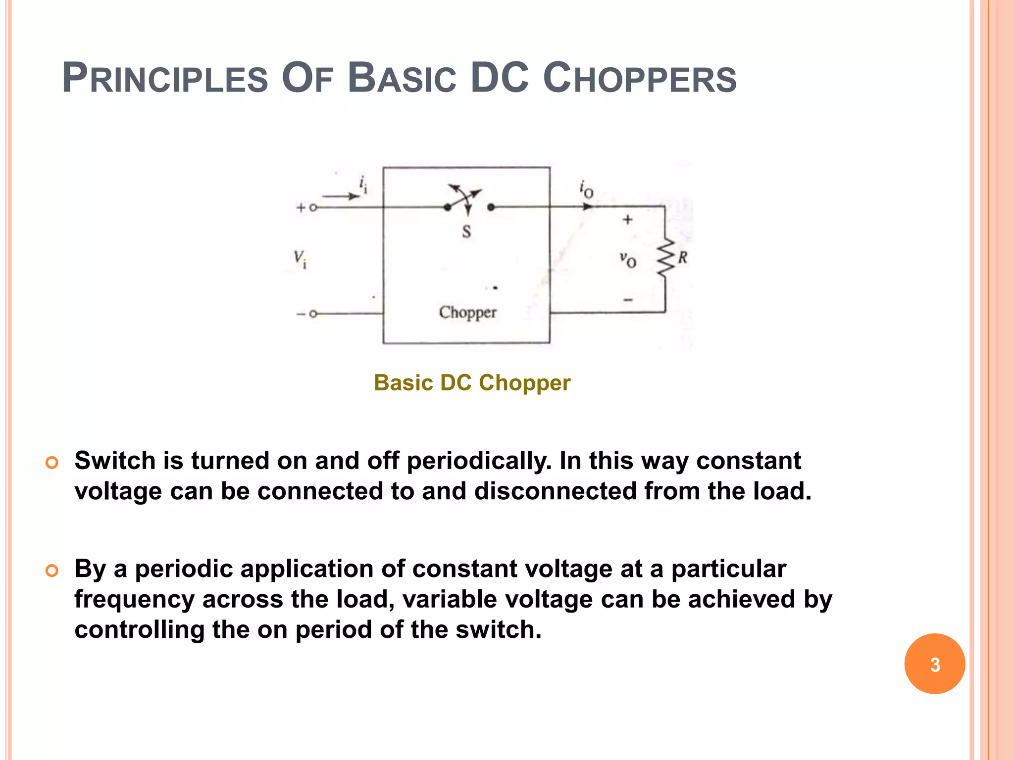
This document discusses different types of DC-DC converters known as choppers. It describes:
1) Buck and boost choppers, where buck choppers produce output voltages lower than the input, and boost choppers produce outputs higher than the input.
2) The basic operation of choppers which involves turning a switch on and off periodically to connect and disconnect a constant voltage source from the load, allowing variable output voltages.
3) Key circuits for buck, boost, and buck-boost choppers along with explanations of how energy transfer from input to output works during switch on and off periods to achieve different output voltages.
Introduction, equipment required for HVDC systems, Comparison of AC and DC Transmission, Limitations of HVDC transmission lines, reliability of HVDC systems, comparison of HVDC link with EHVAC link, HVDC system configuration and components, fundamental equations in HVDC system, HVDC links, converter theory and performance equation, valve characteristic, converter circuits, converter transformer testing, multi bridge converters, abnormal operation of HVDC system, control of HVDC system, harmonics and filters. Influence of AC system strength on AC/DC system interaction, response to AC and DC system faults, Concept of reactive power compensation- reactive Power balance in HVDC substations-Effect of angle of advance and extinction angle on reactive power requirement of converters.
HVDC Bridge and Station Configurations
1. General HVDC – HVAC Comparisons
2. Components of a Converter Bridge
3. HVDC scheme configurations
Operation of the HVDC converter
1. General assumptions
2. Rectifier operation with uncontrolled valves and X = 0
3. Rectifier operation with controlled valves and X = 0
4. Rectifier operation with controlled valves and X 0
5. Inverter operation with controlled valves and X 0
6. Commutation and Commutation Failure
7. Reactive Power Requirements
8. Short-circuit capacity requirements for an HVDC terminal.
9. Harmonics and filtering on the AC and DC sides
Conventional and emerging converter technologies in hvdc power transmission s...Naveed Shahzad
The efficiency of HVDC system is primarily associated with power electronic converters which are playing the key role in transforming AC to DC and vice versa. There have been several converter topologies known and implemented in HVDC system throughout the world, however the major converter topologies are line commutated-current source converters (CSC) and self-commutated voltage source converters (VSC). This presentation provides an overview and comparison of CSC and VSC converters including their applications, advantages, limitations and new technological advancement related to CSC, and VSC including 2 level VSC and 3 level VSC and newer modular multilevel converter (MMC) topologies.
Introduction, Operation of 12-pulse converter as receiving and sending terminals of HVDC system, Equipment required for HVDC System and their significance, Comparison of AC and DC transmission, Control of HVDC transmission
i've made this presentation for my purposes bt if it can help out someone else too then i'll b happy more than for myself. i think these slides help you a lot to understand the concepts of HVDC transmission.And may be you like the way i present it.....
High Voltage Direct Current Transmission SystemNadeem Khilji
The development of HVDC (High Voltage Direct Current) transmission system dates back to the 1930s when mercury arc rectifiers were invented. Since the 1960s, HVDC transmission system is now a mature technology and has played a vital part in both long distance transmission and in the interconnection of systems. Transmitting power at high voltage and in DC form instead of AC is a new technology proven to be economic and simple in operation which is HVDC transmission. HVDC transmission systems, when installed, often form the backbone of an electric power system. They combine high reliability with a long useful life. An HVDC link avoids some of the disadvantages and limitations of AC transmission. HVDC transmission refers to that the AC power generated at a power plant is transformed into DC power before its transmission. At the inverter (receiving side), it is then transformed back into its original AC power and then supplied to each household. Such power transmission method makes it possible to transmit electric power in an economic way.
ER Publication,
IJETR, IJMCTR,
Journals,
International Journals,
High Impact Journals,
Monthly Journal,
Good quality Journals,
Research,
Research Papers,
Research Article,
Free Journals, Open access Journals,
erpublication.org,
Engineering Journal,
Science Journals,
High Frequency Soft Switching Of PWM Boost Converter Using Auxiliary Resonant...IJERA Editor
This thesis presents High frequency Soft Switching DC-DC boost Converter. The circuit consists of a general Boost Converter with an additional resonant circuit which has a switch, inductor, capacitor and a diode.In general Boost Converter circuits have snubber circuits where switching losses are dissipated in external passive resistors; which is known as hard switching. As the switching frequency of PWM converters is increased its switching losses and conduction losses also increases. This restricts the use of PWM technique. New Zero Voltage Transition-Zero Current Transition (ZVT-ZCT) PWM converter equipped with the snubber provides the most desirable features of both ZVT and ZCT converters presented previously. Moreover all semiconductors devices operate with soft switching and hence losses are reduced.
Immunizing Image Classifiers Against Localized Adversary Attacksgerogepatton
This paper addresses the vulnerability of deep learning models, particularly convolutional neural networks
(CNN)s, to adversarial attacks and presents a proactive training technique designed to counter them. We
introduce a novel volumization algorithm, which transforms 2D images into 3D volumetric representations.
When combined with 3D convolution and deep curriculum learning optimization (CLO), itsignificantly improves
the immunity of models against localized universal attacks by up to 40%. We evaluate our proposed approach
using contemporary CNN architectures and the modified Canadian Institute for Advanced Research (CIFAR-10
and CIFAR-100) and ImageNet Large Scale Visual Recognition Challenge (ILSVRC12) datasets, showcasing
accuracy improvements over previous techniques. The results indicate that the combination of the volumetric
input and curriculum learning holds significant promise for mitigating adversarial attacks without necessitating
adversary training.
Hybrid optimization of pumped hydro system and solar- Engr. Abdul-Azeez.pdffxintegritypublishin
Advancements in technology unveil a myriad of electrical and electronic breakthroughs geared towards efficiently harnessing limited resources to meet human energy demands. The optimization of hybrid solar PV panels and pumped hydro energy supply systems plays a pivotal role in utilizing natural resources effectively. This initiative not only benefits humanity but also fosters environmental sustainability. The study investigated the design optimization of these hybrid systems, focusing on understanding solar radiation patterns, identifying geographical influences on solar radiation, formulating a mathematical model for system optimization, and determining the optimal configuration of PV panels and pumped hydro storage. Through a comparative analysis approach and eight weeks of data collection, the study addressed key research questions related to solar radiation patterns and optimal system design. The findings highlighted regions with heightened solar radiation levels, showcasing substantial potential for power generation and emphasizing the system's efficiency. Optimizing system design significantly boosted power generation, promoted renewable energy utilization, and enhanced energy storage capacity. The study underscored the benefits of optimizing hybrid solar PV panels and pumped hydro energy supply systems for sustainable energy usage. Optimizing the design of solar PV panels and pumped hydro energy supply systems as examined across diverse climatic conditions in a developing country, not only enhances power generation but also improves the integration of renewable energy sources and boosts energy storage capacities, particularly beneficial for less economically prosperous regions. Additionally, the study provides valuable insights for advancing energy research in economically viable areas. Recommendations included conducting site-specific assessments, utilizing advanced modeling tools, implementing regular maintenance protocols, and enhancing communication among system components.
Hierarchical Digital Twin of a Naval Power SystemKerry Sado
A hierarchical digital twin of a Naval DC power system has been developed and experimentally verified. Similar to other state-of-the-art digital twins, this technology creates a digital replica of the physical system executed in real-time or faster, which can modify hardware controls. However, its advantage stems from distributing computational efforts by utilizing a hierarchical structure composed of lower-level digital twin blocks and a higher-level system digital twin. Each digital twin block is associated with a physical subsystem of the hardware and communicates with a singular system digital twin, which creates a system-level response. By extracting information from each level of the hierarchy, power system controls of the hardware were reconfigured autonomously. This hierarchical digital twin development offers several advantages over other digital twins, particularly in the field of naval power systems. The hierarchical structure allows for greater computational efficiency and scalability while the ability to autonomously reconfigure hardware controls offers increased flexibility and responsiveness. The hierarchical decomposition and models utilized were well aligned with the physical twin, as indicated by the maximum deviations between the developed digital twin hierarchy and the hardware.
Welcome to WIPAC Monthly the magazine brought to you by the LinkedIn Group Water Industry Process Automation & Control.
In this month's edition, along with this month's industry news to celebrate the 13 years since the group was created we have articles including
A case study of the used of Advanced Process Control at the Wastewater Treatment works at Lleida in Spain
A look back on an article on smart wastewater networks in order to see how the industry has measured up in the interim around the adoption of Digital Transformation in the Water Industry.
Cosmetic shop management system project report.pdfKamal Acharya
Buying new cosmetic products is difficult. It can even be scary for those who have sensitive skin and are prone to skin trouble. The information needed to alleviate this problem is on the back of each product, but it's thought to interpret those ingredient lists unless you have a background in chemistry.
Instead of buying and hoping for the best, we can use data science to help us predict which products may be good fits for us. It includes various function programs to do the above mentioned tasks.
Data file handling has been effectively used in the program.
The automated cosmetic shop management system should deal with the automation of general workflow and administration process of the shop. The main processes of the system focus on customer's request where the system is able to search the most appropriate products and deliver it to the customers. It should help the employees to quickly identify the list of cosmetic product that have reached the minimum quantity and also keep a track of expired date for each cosmetic product. It should help the employees to find the rack number in which the product is placed.It is also Faster and more efficient way.
Explore the innovative world of trenchless pipe repair with our comprehensive guide, "The Benefits and Techniques of Trenchless Pipe Repair." This document delves into the modern methods of repairing underground pipes without the need for extensive excavation, highlighting the numerous advantages and the latest techniques used in the industry.
Learn about the cost savings, reduced environmental impact, and minimal disruption associated with trenchless technology. Discover detailed explanations of popular techniques such as pipe bursting, cured-in-place pipe (CIPP) lining, and directional drilling. Understand how these methods can be applied to various types of infrastructure, from residential plumbing to large-scale municipal systems.
Ideal for homeowners, contractors, engineers, and anyone interested in modern plumbing solutions, this guide provides valuable insights into why trenchless pipe repair is becoming the preferred choice for pipe rehabilitation. Stay informed about the latest advancements and best practices in the field.
Sachpazis:Terzaghi Bearing Capacity Estimation in simple terms with Calculati...Dr.Costas Sachpazis
Terzaghi's soil bearing capacity theory, developed by Karl Terzaghi, is a fundamental principle in geotechnical engineering used to determine the bearing capacity of shallow foundations. This theory provides a method to calculate the ultimate bearing capacity of soil, which is the maximum load per unit area that the soil can support without undergoing shear failure. The Calculation HTML Code included.
Student information management system project report ii.pdfKamal Acharya
Our project explains about the student management. This project mainly explains the various actions related to student details. This project shows some ease in adding, editing and deleting the student details. It also provides a less time consuming process for viewing, adding, editing and deleting the marks of the students.
Saudi Arabia stands as a titan in the global energy landscape, renowned for its abundant oil and gas resources. It's the largest exporter of petroleum and holds some of the world's most significant reserves. Let's delve into the top 10 oil and gas projects shaping Saudi Arabia's energy future in 2024.
1. DC-DC CONVERTER OR CHOPPER
M&V Patel Department of Electrical Engineering
Faculty of Technology and Engineering
Charotar University of Science and Technology – Changa
Prepared by: Dharmesh A Dabhi
Assistant Professor
2. INTRODUCTION
DC-DC converter (chopper) is used to convert constant DC
voltage into variable DC voltage.
In DC-DC conversion circuits, thyristors are used as switching
elements. Here thyristors must be turned off using forced
commutation as they lack facility of natural commutation that is
available in AC circuits.
Buck chopper produces output that is less than or equal to input
voltage.
Boost chopper provides an output voltage that is greater than or
equal to input voltage.
Typical application of DC choppers is DC motor speed control.
2
3. PRINCIPLES OF BASIC DC CHOPPERS
Switch is turned on and off periodically. In this way constant
voltage can be connected to and disconnected from the load.
By a periodic application of constant voltage at a particular
frequency across the load, variable voltage can be achieved by
controlling the on period of the switch.
3
Basic DC Chopper
4. Instantaneous voltage across load is either zero (S off) or Vi
(S on).
Average (DC) output voltage over a cycle is:
V0= TON Vi
TON+TOFF
V0=TON Vi
T
V0=d Vi 4
5. 5
Output voltage as function of duty cycle
Output voltage varies linearly with duty cycle.
It is possible to control output voltage from zero to Vi as duty cycle
varies from zero to 1.
6. METHODS FOR VARYING AVERAGE OUTPUT
VOLTAGE
Pulse width TON is varied
while overall switching
period is kept constant.
Pulse width TON or Toff is
kept constant while the
period (frequency) is
varied.
Pulse-Width Modulation Pulse-Frequency Modulation
6
9. 9
Continous Current Mode
As elements are ideal, DC
power drawn from source
must equal the DC power
absorbed by load.
P0 = Pi
V0 I0 = Vi Ii
I0 =Vi * Ii
V0
=Vi * Ii
Vi d
I0 = Ii_
d
13. When S is on (D is off),
capacitor energy supplies the
load voltage.
Vo=Vc (if capacitor is charged)
During on-state of switch S,
voltage across inductor
instantly becomes equal to
input supply voltage. Current
through it increases gradually
and stores energy in its
magnetic field.
For very first time, when S is
closed Vo=0, as capacitor is
not charged.
When S is off (D is on),
inductor voltage reverses its
polarity and adds in input
voltage to provide output
voltage which is equal to:
V0=Vi+VL
During off state of S, capacitor
charges and voltage at it
gradually build up to Vi+VL
(This capacitor voltages serves
as load voltage when next time
S in on)
If S is off forever, inductor acts
as short circuit. It does not
develop any voltage and
Vo= Vi
On-State Off-State
13
14. 14
Voltage and current
waveforms for duty cycle
50%
d= 0.5 means Switch is on and
off for equal time intervals.
Energy that inductor develops
during on-state is completely
dessipated during off-state.
If duty cycle increases above
0.5, inductor will not
dessipate its energy
completely in off-states. The
remaining inductor voltage
(due to left-over energy) adds
up next time when switch is
off and more increased
voltage appears at output.
15. 15
If duty cycle increases above 0.5, inductor will not dessipate its
energy completely in off-states. The remaining inductor voltage (due
to left-over energy) adds up next time when switch is off and more
increased voltage appears at output.
Neglecting losses, energy transferred by inductance during TOFF
must equal the energy gained by it during period TON
Final expression for output load voltage is:
Vo=Vi [1/(1-d)]
If switch is open (d=0), output voltage is equal to input
voltage. As d increases, output voltage becomes larger than
input voltage.
So output voltage is always higher than input voltage if switch
is operated at an appropriately high frequency.