Downloaded 419 times
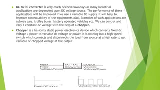
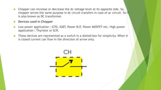


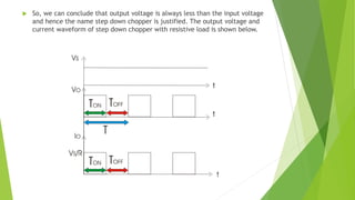
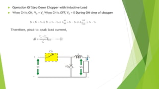


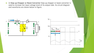
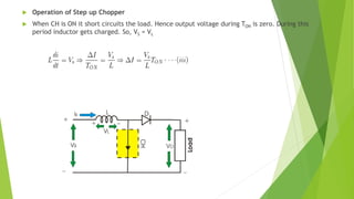


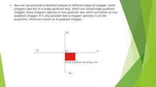


This document provides an introduction and overview of chopper circuits, which are power electronics devices that can convert a fixed DC voltage into a variable DC voltage. It defines a chopper as a high-speed switch that connects and disconnects a load from a power source rapidly to produce a variable output voltage. Choppers can either step up or step down the output voltage relative to the input. Different types of choppers are described including step-down, step-up, buck-boost, and various configurations classified by their operating quadrants on a voltage-current plane (types A, B, and C). Key components like switches, diodes, and inductors are also outlined.


