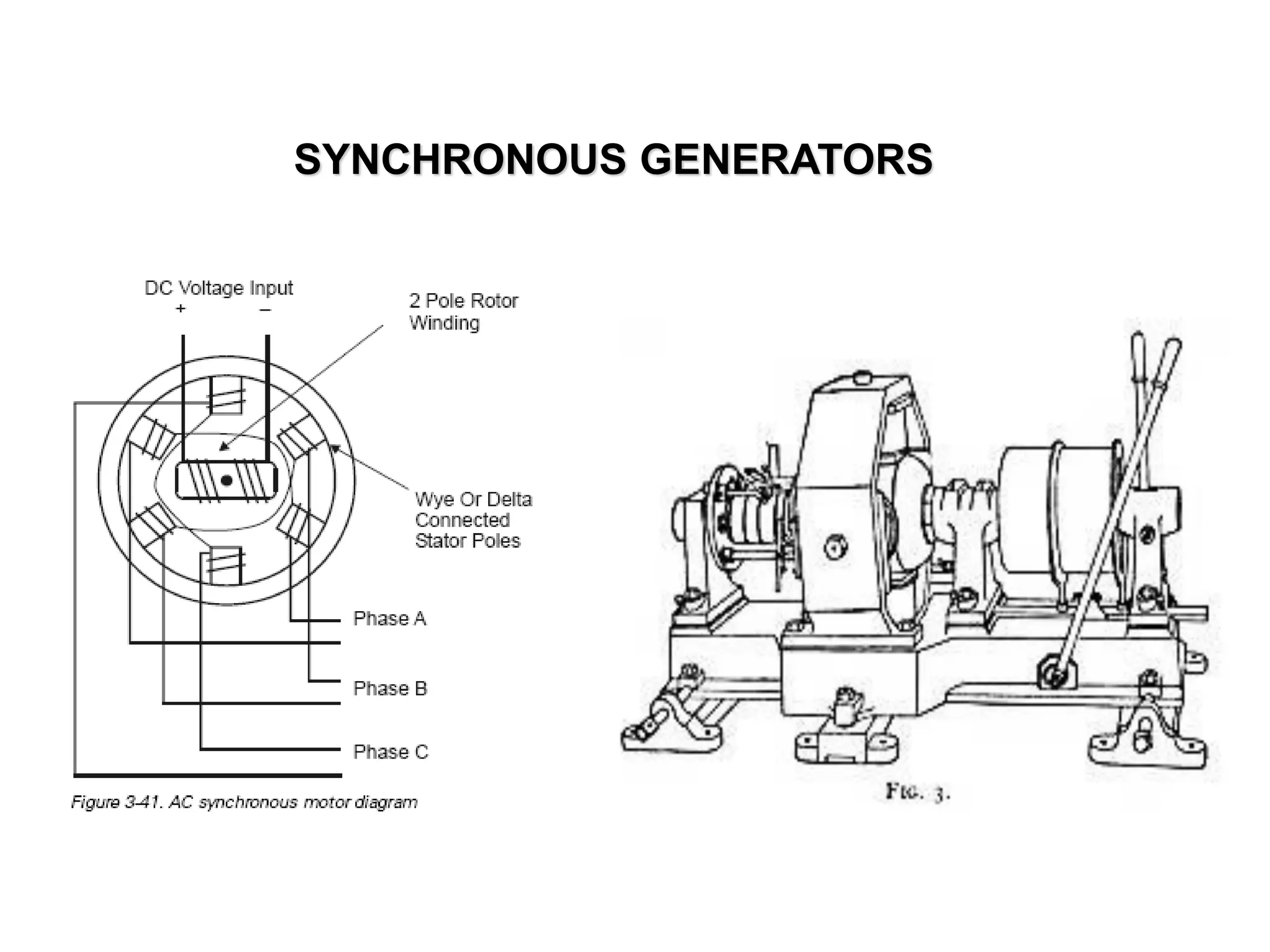
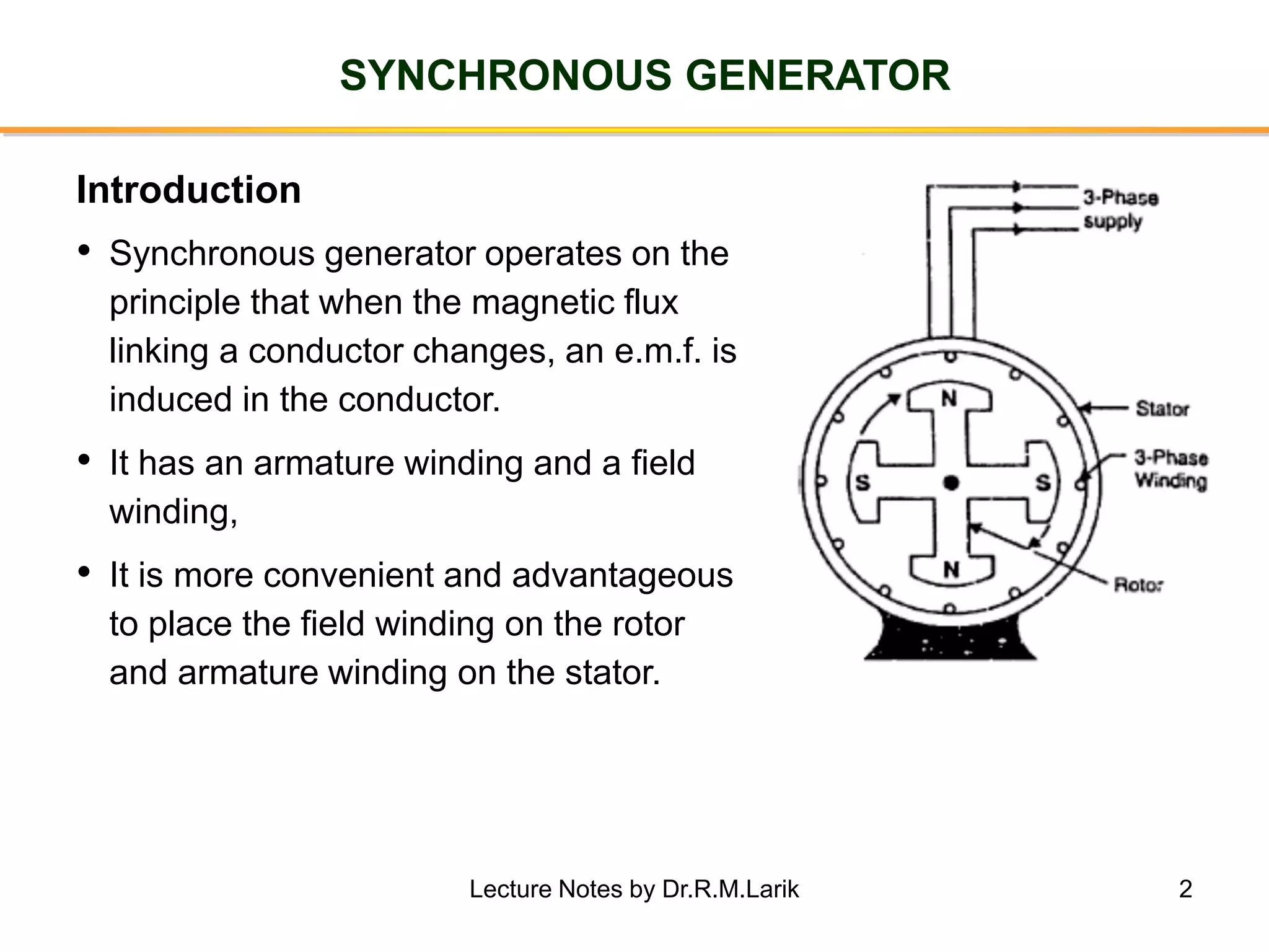
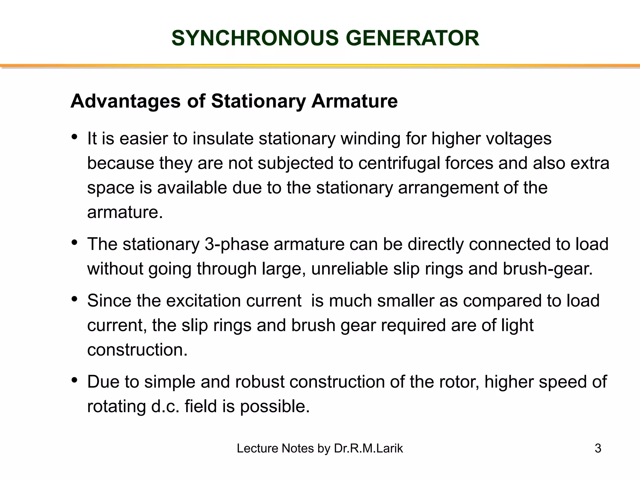
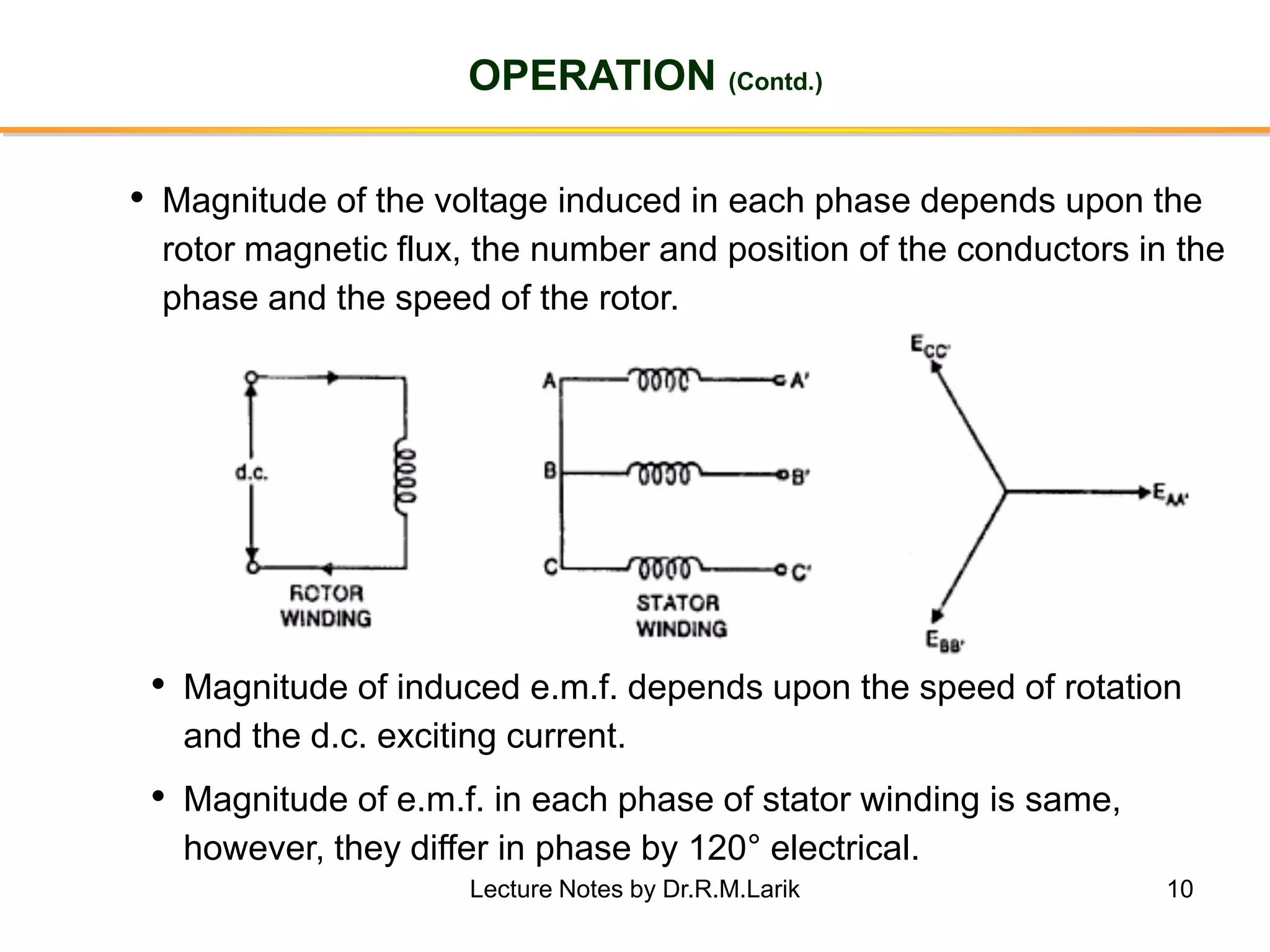
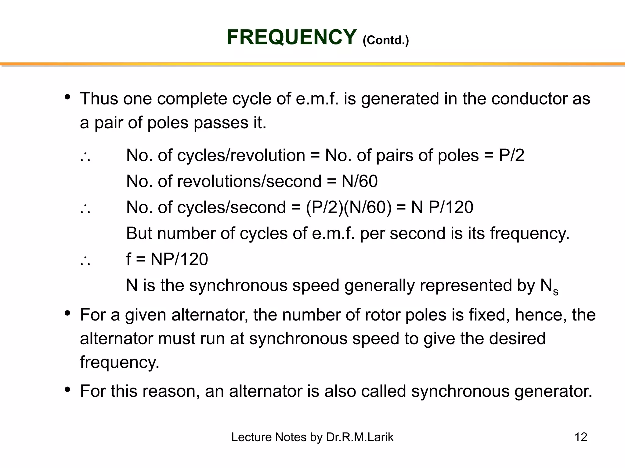
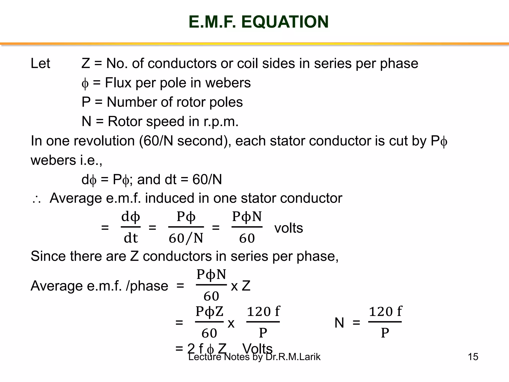
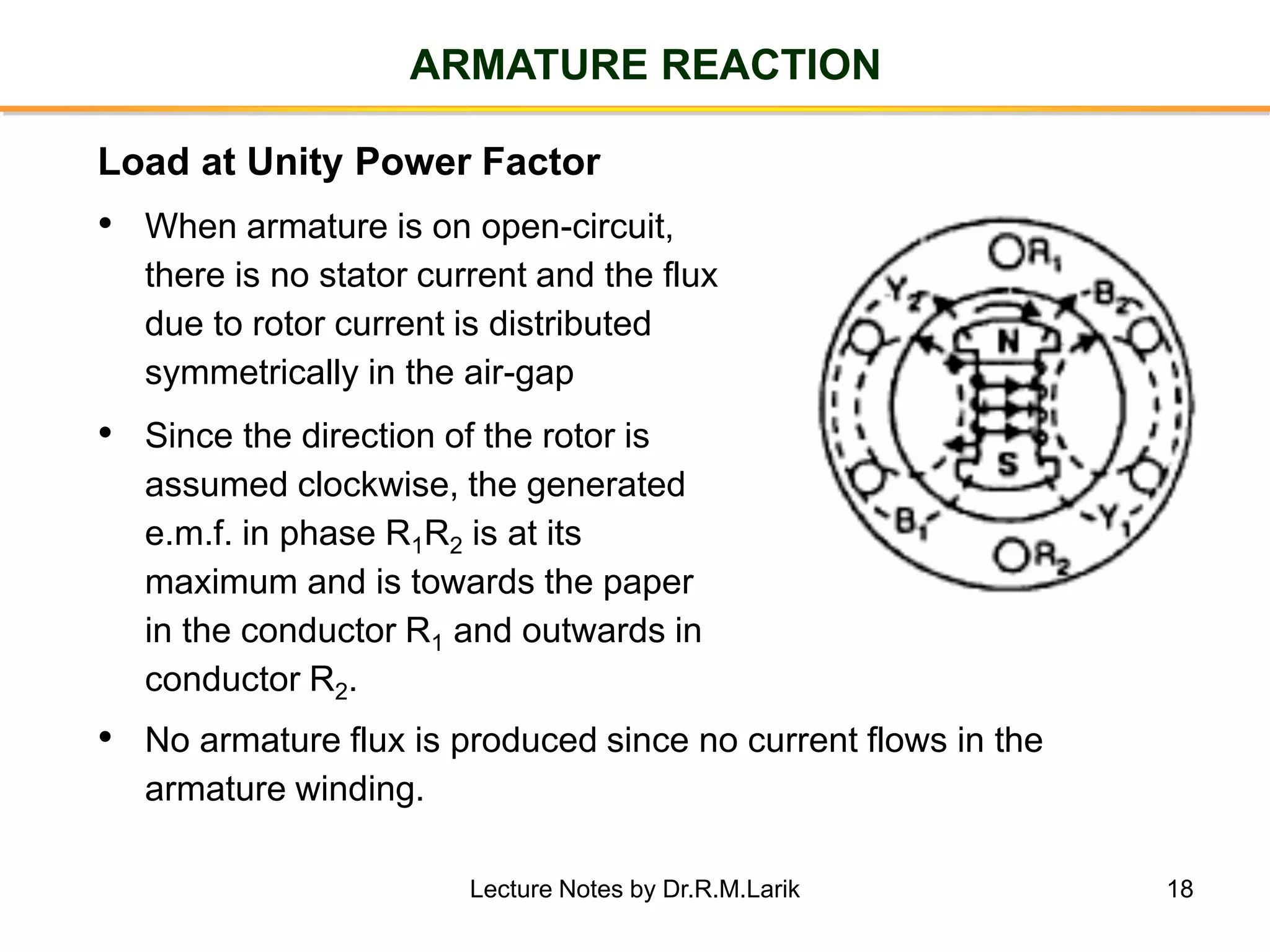
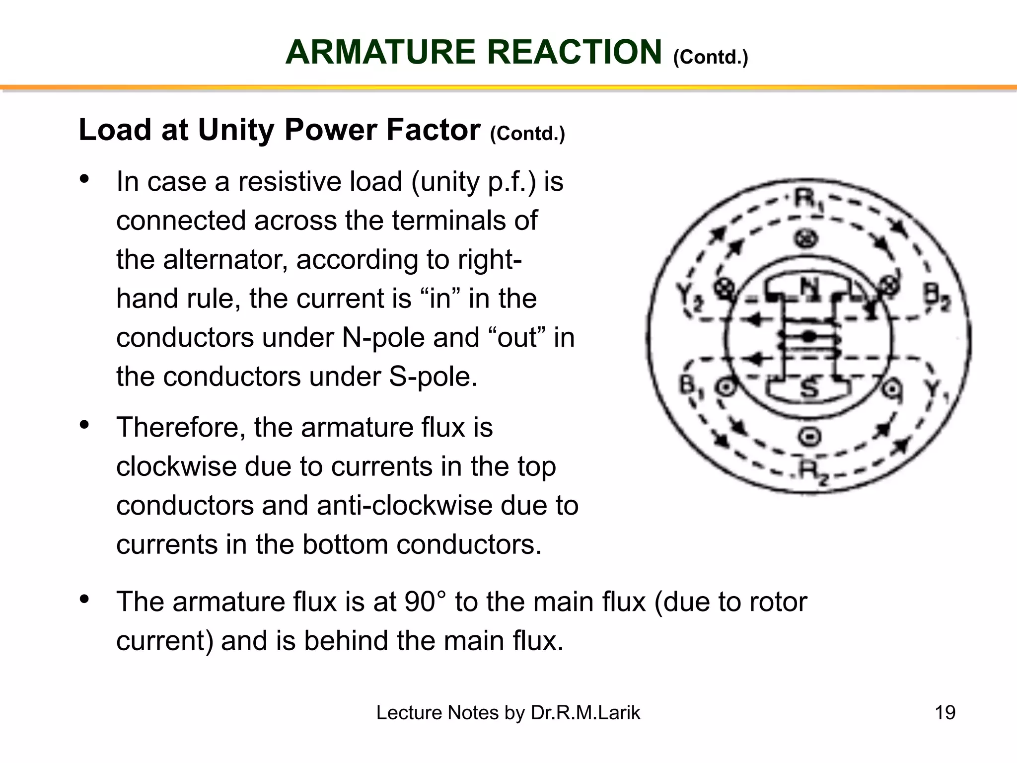
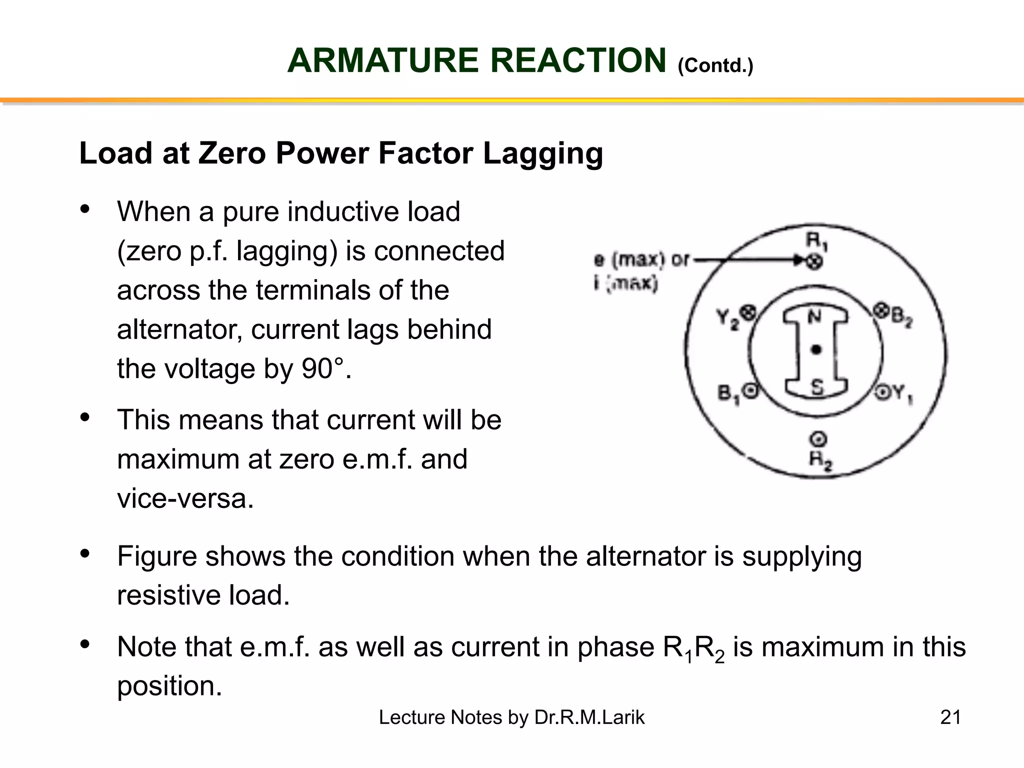
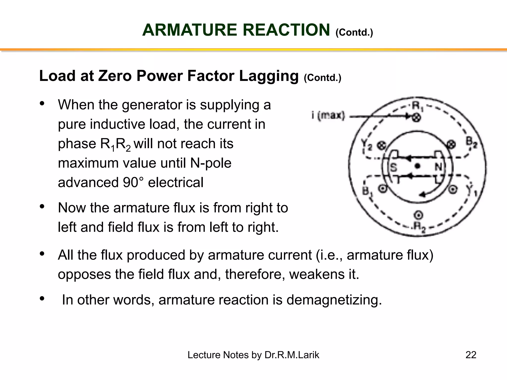
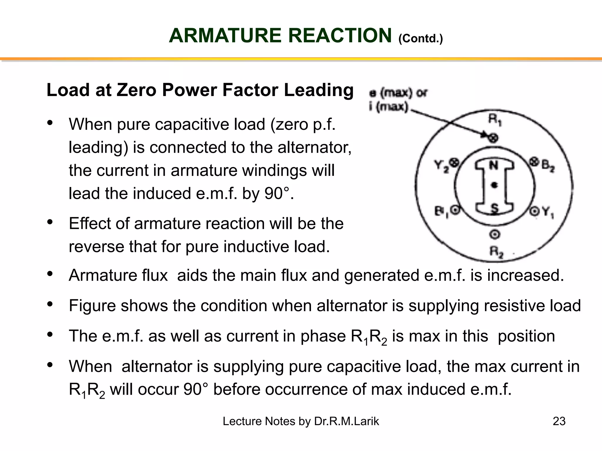
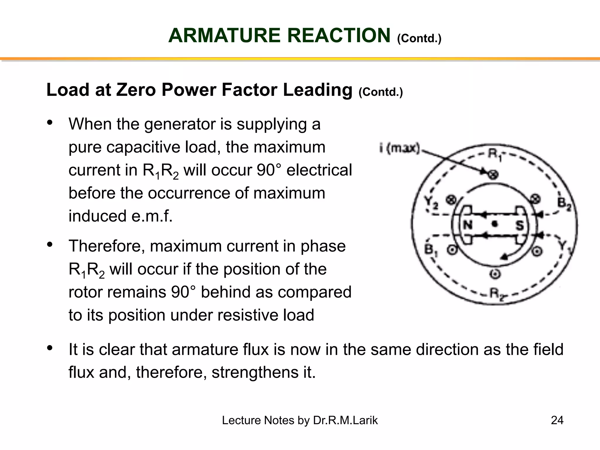
Synchronous generators operate on the principle of electromagnetic induction. They have a stationary armature winding and a rotating field winding supplied by a direct current source. It is advantageous to have the field winding on the rotor and armature winding on the stator because it allows for easier insulation of the high voltage winding and direct connection to the load. The frequency of the induced voltage depends on the number of rotor poles and its rotational speed. Armature reaction is the effect of the armature magnetic field on the main rotor field, distorting or strengthening it depending on the load power factor.
Part of Lecture series on EEE-413, Electrical Drives (DC Drives) delivered by me to students of VIII Semester B.E. (Electrical), Session 2018-19.
Z. H. College of Engg. & Technology, Aligarh Muslim University, Aligarh.
Missing materials will be uploaded shortly.
Please comment and feel free to ask anything related. Thanks!
Synchronous generator is a machine which converts mechanical power into electrical power. Three phase synchronous machine are used in thermal , hydro power plant to generate the electrical. Synchronous generator is used to generate the large number of electricity
Physical Description
Mathematical Model
Park's "dqo" transportation
Steady-state Analysis
phasor representation in d-q coordinates
link with network equations
Definition of "rotor angle"
Representation of Synchronous Machines in Stability Studies
neglect of stator transients
magnetic saturation
Simplified Models
Synchronous Machine Parameters
Reactive Capability Limits
Consists of two sets of windings:
3 phase armature winding on the stator distributed with centres 120° apart in space
field winding on the rotor supplied by DC
Two basic rotor structures used:
salient or projecting pole structure for hydraulic units (low speed)
round rotor structure for thermal units (high speed)
Salient poles have concentrated field windings; usually also carry damper windings on the pole face.Round rotors have solid steel rotors with distributed windings
Nearly sinusoidal space distribution of flux wave shape obtained by:
distributing stator windings and field windings in many slots (round rotor);
shaping pole faces (salient pole)
Electric Drives and Controls Unit 1 IntroductionDr.Raja R
Electric Drives and Controls
Unit 1 Introduction
Block Diagram of Electric Drive
Power Source
Power Modulator
Load
Control Unit
Sensing Unit
Motor
Classification of Electrical Drives
Advantages of Electrical Drives
Disadvantages of Electrical Drive
Applications of Electrical Drives
A reluctance motor is a type of electric motor that induces non-permanent magnetic poles on the ferromagnetic rotor. The rotor does not have any windings. It generates torque through magnetic reluctance.
Reluctance motor sub types include synchronous, variable, switched and variable stepping.
Reluctance motors can deliver high power density at low cost, making them attractive for many applications. Disadvantages include high torque ripple (the difference between maximum and minimum torque during one revolution) when operated at low speed, and noise due to torque ripple.
Visualization of magnetic field produced by the field winding excitation with...BhangaleSonal
There are a few ways to detect magnetic fields, one of the most reliable is with magnetic viewer film. This unique film suspends tiny nickel particles over a thin layer of viscous material allowing the particles to align with magnetic fields. It shows the location, as well as how many poles, a magnet has. Magnetic field lines can be drawn by moving a small compass from point to point around a magnet. At each point, draw a short line in the direction of the compass needle. Joining the points together reveals the path of the magnetic field lines.
Hierarchical Digital Twin of a Naval Power SystemKerry Sado
A hierarchical digital twin of a Naval DC power system has been developed and experimentally verified. Similar to other state-of-the-art digital twins, this technology creates a digital replica of the physical system executed in real-time or faster, which can modify hardware controls. However, its advantage stems from distributing computational efforts by utilizing a hierarchical structure composed of lower-level digital twin blocks and a higher-level system digital twin. Each digital twin block is associated with a physical subsystem of the hardware and communicates with a singular system digital twin, which creates a system-level response. By extracting information from each level of the hierarchy, power system controls of the hardware were reconfigured autonomously. This hierarchical digital twin development offers several advantages over other digital twins, particularly in the field of naval power systems. The hierarchical structure allows for greater computational efficiency and scalability while the ability to autonomously reconfigure hardware controls offers increased flexibility and responsiveness. The hierarchical decomposition and models utilized were well aligned with the physical twin, as indicated by the maximum deviations between the developed digital twin hierarchy and the hardware.
Student information management system project report ii.pdfKamal Acharya
Our project explains about the student management. This project mainly explains the various actions related to student details. This project shows some ease in adding, editing and deleting the student details. It also provides a less time consuming process for viewing, adding, editing and deleting the marks of the students.
Explore the innovative world of trenchless pipe repair with our comprehensive guide, "The Benefits and Techniques of Trenchless Pipe Repair." This document delves into the modern methods of repairing underground pipes without the need for extensive excavation, highlighting the numerous advantages and the latest techniques used in the industry.
Learn about the cost savings, reduced environmental impact, and minimal disruption associated with trenchless technology. Discover detailed explanations of popular techniques such as pipe bursting, cured-in-place pipe (CIPP) lining, and directional drilling. Understand how these methods can be applied to various types of infrastructure, from residential plumbing to large-scale municipal systems.
Ideal for homeowners, contractors, engineers, and anyone interested in modern plumbing solutions, this guide provides valuable insights into why trenchless pipe repair is becoming the preferred choice for pipe rehabilitation. Stay informed about the latest advancements and best practices in the field.
About
Indigenized remote control interface card suitable for MAFI system CCR equipment. Compatible for IDM8000 CCR. Backplane mounted serial and TCP/Ethernet communication module for CCR remote access. IDM 8000 CCR remote control on serial and TCP protocol.
• Remote control: Parallel or serial interface.
• Compatible with MAFI CCR system.
• Compatible with IDM8000 CCR.
• Compatible with Backplane mount serial communication.
• Compatible with commercial and Defence aviation CCR system.
• Remote control system for accessing CCR and allied system over serial or TCP.
• Indigenized local Support/presence in India.
• Easy in configuration using DIP switches.
Technical Specifications
Indigenized remote control interface card suitable for MAFI system CCR equipment. Compatible for IDM8000 CCR. Backplane mounted serial and TCP/Ethernet communication module for CCR remote access. IDM 8000 CCR remote control on serial and TCP protocol.
Key Features
Indigenized remote control interface card suitable for MAFI system CCR equipment. Compatible for IDM8000 CCR. Backplane mounted serial and TCP/Ethernet communication module for CCR remote access. IDM 8000 CCR remote control on serial and TCP protocol.
• Remote control: Parallel or serial interface
• Compatible with MAFI CCR system
• Copatiable with IDM8000 CCR
• Compatible with Backplane mount serial communication.
• Compatible with commercial and Defence aviation CCR system.
• Remote control system for accessing CCR and allied system over serial or TCP.
• Indigenized local Support/presence in India.
Application
• Remote control: Parallel or serial interface.
• Compatible with MAFI CCR system.
• Compatible with IDM8000 CCR.
• Compatible with Backplane mount serial communication.
• Compatible with commercial and Defence aviation CCR system.
• Remote control system for accessing CCR and allied system over serial or TCP.
• Indigenized local Support/presence in India.
• Easy in configuration using DIP switches.
Welcome to WIPAC Monthly the magazine brought to you by the LinkedIn Group Water Industry Process Automation & Control.
In this month's edition, along with this month's industry news to celebrate the 13 years since the group was created we have articles including
A case study of the used of Advanced Process Control at the Wastewater Treatment works at Lleida in Spain
A look back on an article on smart wastewater networks in order to see how the industry has measured up in the interim around the adoption of Digital Transformation in the Water Industry.
Final project report on grocery store management system..pdfKamal Acharya
In today’s fast-changing business environment, it’s extremely important to be able to respond to client needs in the most effective and timely manner. If your customers wish to see your business online and have instant access to your products or services.
Online Grocery Store is an e-commerce website, which retails various grocery products. This project allows viewing various products available enables registered users to purchase desired products instantly using Paytm, UPI payment processor (Instant Pay) and also can place order by using Cash on Delivery (Pay Later) option. This project provides an easy access to Administrators and Managers to view orders placed using Pay Later and Instant Pay options.
In order to develop an e-commerce website, a number of Technologies must be studied and understood. These include multi-tiered architecture, server and client-side scripting techniques, implementation technologies, programming language (such as PHP, HTML, CSS, JavaScript) and MySQL relational databases. This is a project with the objective to develop a basic website where a consumer is provided with a shopping cart website and also to know about the technologies used to develop such a website.
This document will discuss each of the underlying technologies to create and implement an e- commerce website.
Sachpazis:Terzaghi Bearing Capacity Estimation in simple terms with Calculati...Dr.Costas Sachpazis
Terzaghi's soil bearing capacity theory, developed by Karl Terzaghi, is a fundamental principle in geotechnical engineering used to determine the bearing capacity of shallow foundations. This theory provides a method to calculate the ultimate bearing capacity of soil, which is the maximum load per unit area that the soil can support without undergoing shear failure. The Calculation HTML Code included.
CFD Simulation of By-pass Flow in a HRSG module by R&R Consult.pptxR&R Consult
CFD analysis is incredibly effective at solving mysteries and improving the performance of complex systems!
Here's a great example: At a large natural gas-fired power plant, where they use waste heat to generate steam and energy, they were puzzled that their boiler wasn't producing as much steam as expected.
R&R and Tetra Engineering Group Inc. were asked to solve the issue with reduced steam production.
An inspection had shown that a significant amount of hot flue gas was bypassing the boiler tubes, where the heat was supposed to be transferred.
R&R Consult conducted a CFD analysis, which revealed that 6.3% of the flue gas was bypassing the boiler tubes without transferring heat. The analysis also showed that the flue gas was instead being directed along the sides of the boiler and between the modules that were supposed to capture the heat. This was the cause of the reduced performance.
Based on our results, Tetra Engineering installed covering plates to reduce the bypass flow. This improved the boiler's performance and increased electricity production.
It is always satisfying when we can help solve complex challenges like this. Do your systems also need a check-up or optimization? Give us a call!
Work done in cooperation with James Malloy and David Moelling from Tetra Engineering.
More examples of our work https://www.r-r-consult.dk/en/cases-en/
2. 2
SYNCHRONOUS GENERATOR
• Synchronous generator operates on the
principle that when the magnetic flux
linking a conductor changes, an e.m.f. is
induced in the conductor.
• It has an armature winding and a field
winding,
• It is more convenient and advantageous
to place the field winding on the rotor
and armature winding on the stator.
Introduction
Lecture Notes by Dr.R.M.Larik
3. 3
SYNCHRONOUS GENERATOR
• It is easier to insulate stationary winding for higher voltages
because they are not subjected to centrifugal forces and also extra
space is available due to the stationary arrangement of the
armature.
• The stationary 3-phase armature can be directly connected to load
without going through large, unreliable slip rings and brush-gear.
• Since the excitation current is much smaller as compared to load
current, the slip rings and brush gear required are of light
construction.
• Due to simple and robust construction of the rotor, higher speed of
rotating d.c. field is possible.
Advantages of Stationary Armature
Lecture Notes by Dr.R.M.Larik
4. 4
CONSTRUCTION OF SYNCHRONOUS GENERATOR
• It is the stationary part of the machine and is built up of sheet-steel
laminations having slots on its inner periphery.
• A 3-phase winding is placed in these slots and serves as the
armature winding of the alternator.
• The armature winding is connected in star with neutral grounded.
Stator
Rotor
• The rotor carries a field winding supplied with direct current
through the slip rings by a separate d.c. source.
• This d.c. source (exciter) is generally a small d.c. generator
mounted on the shaft of the alternator.
• Rotor construction is of salient (projected) pole type and non-
salient (cylindrical) pole typeLecture Notes by Dr.R.M.Larik
5. 5
CONSTRUCTION OF SYNCHRONOUS GENERATOR (Contd.)
Rotor (Contd.)
• In this type, salient or projected
poles are mounted on a large
circular steel frame which is
fixed to the shaft of the
alternator.
• The individual field pole
windings are connected in series
such that when the field winding
is energized by the exciter,
adjacent poles have opposite
polarities.
Salient Pole Type
Lecture Notes by Dr.R.M.Larik
6. 6
CONSTRUCTION OF SYNCHRONOUS GENERATOR (Contd.)
Rotor (Contd.)
• Low and medium-speed alternators (120-400 r.p.m.), those driven
by diesel engines or water turbines, have salient pole type rotors
due to the following reasons:
− The salient field poles would cause an excessive windage
loss if driven at high speed and would tend to produce noise.
− Salient-pole construction cannot be made strong enough to
withstand the mechanical stresses to which they may be
subjected at higher speeds.
Salient Pole Type (Contd.)
• For a frequency of 50 Hz, we must use a large number of poles
on the rotor of slow-speed alternators.
• Low-speed rotors possess a large diameter to provide necessary
space for the poles.Lecture Notes by Dr.R.M.Larik
7. 7
CONSTRUCTION OF SYNCHRONOUS GENERATOR (Contd.)
Rotor (Contd.)
• Non-salient pole type rotor is made
of smooth solid forged-steel
cylinder having a number of slots
along the outer surface.
• Field windings are embedded in
the slots and are connected in
series to the slip rings through
which they are energized by the
d.c. exciter.
• The regions forming the poles are
left unslotted.
Non-Salient Pole Type
Lecture Notes by Dr.R.M.Larik
8. 8
CONSTRUCTION OF SYNCHRONOUS GENERATOR (Contd.)
Rotor (Contd.)
• High-speed generators (1500 or 3000 r.p.m.), driven by steam
turbines, use non-salient type rotors due to the reasons:
− It gives noiseless operation at high speeds.
− The flux distribution around the periphery is nearly a sine wave
and hence a better e.m.f. waveform is obtained than in the case
of salient-pole type.
• Since steam turbines run at high speed and a frequency of 50 Hz is
required, we need a small number of poles on the rotor.
• We can not use less than 2 poles, hence, the highest possible
speed will be 3000 r.p.m.
Non-Salient Pole Type (Contd.)
Lecture Notes by Dr.R.M.Larik
9. 9
OPERATION
• The rotor winding is energized from the d.c. exciter and alternate N
and S poles are developed on the rotor.
• When the rotor is rotated in anti-clockwise direction by a prime
mover, the stator or armature conductors are cut by the magnetic
flux of rotor poles.
• Consequently, e.m.f. is induced in the armature conductors due to
electromagnetic induction.
• The induced e.m.f. is alternating since N and S poles of rotor
alternately pass the armature conductors.
• Direction of the induced e.m.f. can be determined by Fleming’s right
hand rule and the frequency is given by;
f = NP/120
where N = speed of rotor in r.p.m.
P = number of rotor polesLecture Notes by Dr.R.M.Larik
10. 10
OPERATION (Contd.)
• Magnitude of the voltage induced in each phase depends upon the
rotor magnetic flux, the number and position of the conductors in the
phase and the speed of the rotor.
• Magnitude of induced e.m.f. depends upon the speed of rotation
and the d.c. exciting current.
• Magnitude of e.m.f. in each phase of stator winding is same,
however, they differ in phase by 120° electrical.
Lecture Notes by Dr.R.M.Larik
11. 11
FREQUENCY
• Frequency of induced e.m.f. in the stator depends on speed and the
number of poles.
Let N = rotor speed in r.p.m.
P = number of rotor poles
f = frequency of e.m.f. in Hz
• Consider a stator conductor that is successively swept by the N and
S poles of the rotor.
• If a positive voltage is induced when a N-pole sweeps across the
conductor, a similar negative voltage is induced when a S-pole
sweeps.
Lecture Notes by Dr.R.M.Larik
12. 12
FREQUENCY (Contd.)
• Thus one complete cycle of e.m.f. is generated in the conductor as
a pair of poles passes it.
No. of cycles/revolution = No. of pairs of poles = P/2
No. of revolutions/second = N/60
No. of cycles/second = (P/2)(N/60) = N P/120
But number of cycles of e.m.f. per second is its frequency.
f = NP/120
N is the synchronous speed generally represented by Ns
• For a given alternator, the number of rotor poles is fixed, hence, the
alternator must run at synchronous speed to give the desired
frequency.
• For this reason, an alternator is also called synchronous generator.
Lecture Notes by Dr.R.M.Larik
13. 13
A.C. ARMATURE WINDINGS
• A.C. armature windings are generally open-circuit type i.e., both ends
are brought out.
• An open-circuit winding is one that does not close on itself i.e., a
closed circuit will not be formed until some external connection is
made to a source or load.
• The following are the general features of a.c. armature windings:
− A.C. armature windings are symmetrically distributed in slots
around the complete circumference of the armature.
− Distributed winding has two principal advantages:
a) Distributed winding generates a voltage in the form of sin wave.
b) Copper is evenly distributed on the armature surface resulting in
uniform heating of winding which can be easily cooled.
Lecture Notes by Dr.R.M.Larik
14. 14
A.C. ARMATURE WINDINGS (Contd.)
− A.C. armature windings may use full-pitch coils or fractional-pitch
coils
− A coil with a span of 180° electrical is called a full-pitch coil with
two sides of the coil occupyng identical positions under adjacent
opposite poles and the e.m.f. generated in the coil is maximum.
− A coil with a span of less than 180° electrical is called a fractional-
pitch coil (For example, a coil with a span of 150° electrical would
be called a 5/6 pitch coil) and the e.m.f. induced in the coil will be
less than that of a full-pitch coil.
− Most of a.c. machines use double layer armature windings i.e. one
coil side lies in the upper half of one slot while the other coil side
lies in the lower half of another slot spaced about one-pole pitch
from the first one.
Lecture Notes by Dr.R.M.Larik
15. 15
E.M.F. EQUATION
Let Z = No. of conductors or coil sides in series per phase
= Flux per pole in webers
P = Number of rotor poles
N = Rotor speed in r.p.m.
In one revolution (60/N second), each stator conductor is cut by P
webers i.e.,
d = P; and dt = 60/N
Average e.m.f. induced in one stator conductor
=
dϕ
dt
=
Pϕ
Τ60 N
=
PϕN
60
volts
Since there are Z conductors in series per phase,
Average e.m.f. /phase =
PϕN
60
x Z
=
PϕZ
60
x
120 f
P
N =
120 f
P
= 2 f Z VoltsLecture Notes by Dr.R.M.Larik
16. 16
E.M.F. EQUATION
R.M.S. value of e.m.f./phase = Average value of e.m.f. per phase x
form factor
= 2 f Z x 1.11 = 2.22 f Z Volts
E r.m.s. per phase = 2.22 f Z volts (i)
If Kp and Kd are the pitch factor and distribution factor of the armature
winding, then,
E r.m.s. per phase = 2.22 Kp Kd f Z Volts (ii)
Sometimes the turns (T) per phase rather than conductors per phase
are specified, in that case, eq. (ii) becomes:
E r.m.s. per phase = 4.44 Kp Kd f T Volts (iii)
The line voltage will depend upon whether the winding is star or delta
connected.
Lecture Notes by Dr.R.M.Larik
17. 17
ARMATURE REACTION
• When an alternator is running at no-load, there will be no current
flowing through the armature winding and magnetic flux produced in
the air-gap will be only due to rotor field.
• When the alternator is loaded, the three-phase currents will produce
an additional magnetic field in the air-gap.
• The effect of armature flux on the flux produced by field ampere-turns
is called armature reaction.
• The armature flux and the flux produced by rotor ampere-turns rotate
at a synchronous speed in the same direction, hence, the two fluxes
are fixed in space relative to each other.
• Modification of flux in the air-gap due to armature flux depends on the
magnitude of stator current and on the power factor of the load.
• Load power factor determines whether the armature flux distorts,
opposes or helps the main flux.
Lecture Notes by Dr.R.M.Larik
18. 18
ARMATURE REACTION
• When armature is on open-circuit,
there is no stator current and the flux
due to rotor current is distributed
symmetrically in the air-gap
• Since the direction of the rotor is
assumed clockwise, the generated
e.m.f. in phase R1R2 is at its
maximum and is towards the paper
in the conductor R1 and outwards in
conductor R2.
Load at Unity Power Factor
• No armature flux is produced since no current flows in the
armature winding.
Lecture Notes by Dr.R.M.Larik
19. 19
ARMATURE REACTION (Contd.)
• In case a resistive load (unity p.f.) is
connected across the terminals of
the alternator, according to right-
hand rule, the current is “in” in the
conductors under N-pole and “out” in
the conductors under S-pole.
• Therefore, the armature flux is
clockwise due to currents in the top
conductors and anti-clockwise due to
currents in the bottom conductors.
Load at Unity Power Factor (Contd.)
• The armature flux is at 90° to the main flux (due to rotor
current) and is behind the main flux.
Lecture Notes by Dr.R.M.Larik
20. 20
ARMATURE REACTION (Contd.)
• In this case, the flux in the air-gap is distorted but not weakened.
• Therefore, at unity p.f., the effect of armature reaction is merely
to distort the main field; there is no weakening of the main field
and the average flux practically remains the same.
• Since the magnetic flux due to stator currents (i.e., armature
flux) rotate; synchronously with the rotor, the flux distortion
remains the same for all positions of the rotor.
Load at Unity Power Factor (Contd.)
Lecture Notes by Dr.R.M.Larik
21. 21
ARMATURE REACTION (Contd.)
• When a pure inductive load
(zero p.f. lagging) is connected
across the terminals of the
alternator, current lags behind
the voltage by 90°.
• This means that current will be
maximum at zero e.m.f. and
vice-versa.
Load at Zero Power Factor Lagging
• Figure shows the condition when the alternator is supplying
resistive load.
• Note that e.m.f. as well as current in phase R1R2 is maximum in this
position.
Lecture Notes by Dr.R.M.Larik
22. 22
ARMATURE REACTION (Contd.)
• When the generator is supplying a
pure inductive load, the current in
phase R1R2 will not reach its
maximum value until N-pole
advanced 90° electrical
• Now the armature flux is from right to
left and field flux is from left to right.
Load at Zero Power Factor Lagging (Contd.)
• All the flux produced by armature current (i.e., armature flux)
opposes the field flux and, therefore, weakens it.
• In other words, armature reaction is demagnetizing.
Lecture Notes by Dr.R.M.Larik
23. 23
ARMATURE REACTION (Contd.)
• When pure capacitive load (zero p.f.
leading) is connected to the alternator,
the current in armature windings will
lead the induced e.m.f. by 90°.
• Effect of armature reaction will be the
reverse that for pure inductive load.
Load at Zero Power Factor Leading
• Armature flux aids the main flux and generated e.m.f. is increased.
• Figure shows the condition when alternator is supplying resistive load
• The e.m.f. as well as current in phase R1R2 is max in this position
• When alternator is supplying pure capacitive load, the max current in
R1R2 will occur 90° before occurrence of max induced e.m.f.
Lecture Notes by Dr.R.M.Larik
24. 24
ARMATURE REACTION (Contd.)
• When the generator is supplying a
pure capacitive load, the maximum
current in R1R2 will occur 90° electrical
before the occurrence of maximum
induced e.m.f.
• Therefore, maximum current in phase
R1R2 will occur if the position of the
rotor remains 90° behind as compared
to its position under resistive load
Load at Zero Power Factor Leading (Contd.)
• It is clear that armature flux is now in the same direction as the field
flux and, therefore, strengthens it.
Lecture Notes by Dr.R.M.Larik
25. 25
ARMATURE REACTION (Contd.)
• This causes an increase in the generated voltage.
• Hence at zero p.f. leading, the armature reaction strengthens the
main flux.
• For intermediate values of p.f, the effect of armature reaction is
partly distorting and partly weakening for inductive loads.
• For capacitive loads, the effect of armature reaction is partly
distorting and partly strengthening.
Load at Zero Power Factor Leading (Contd.)
Lecture Notes by Dr.R.M.Larik
26. 26
ALTERNATOR EQUIVALENT CIRCUIT
• All the quantities are per phase.
E0 = No-load e.m.f.
E = Load induced e.m.f.
• E is induced e.m.f. after
allowing for armature reaction.
• It is equal to phasor difference
of E0 and Ia XAR.
• Terminal voltage V is less than E by the voltage drops in XL and Ra.
E = V + Ia (Ra + j XL )
and E0 = E + Ia ( j XAR )
Lecture Notes by Dr.R.M.Larik
27. 27
SYNCHRONOUS REACTANCE (XS)
• Sum of armature leakage
reactance (XL) and reactance of
armature reaction (XAR) is called
synchronous reactance Xs .
Xs = XL + XAR
• It is a fictitious reactance employed to
account for the voltage effects in the
armature circuit produced by the:
− actual armature leakage reactance
− change in the air-gap flux caused by armature reaction.
• The circuit is simplified as shown.
• Synchronous impedance, Zs = Ra + j Xs
Lecture Notes by Dr.R.M.Larik
28. 28
SYNCHRONOUS REACTANCE (XS) (Contd.)
• Synchronous impedance is the
fictitious impedance employed
to account for the voltage
effects in the armature circuit
produced by the:
− actual armature resistance
− actual armature leakage
reactance
− change in the air-gap flux produced by armature reaction.
• Relationship between generator output voltage and load terminal
voltage is given by:
E0 = V + IaZs
= V + Ia (R + j Xs)
Lecture Notes by Dr.R.M.Larik
29. 29
PHASOR DIAGRAM OF A LOADED ALTERNATOR
• Consider a Y-connected alternator supplying inductive load, the
load p.f. angle being ϕ.
• In the last slide the figure shows the equivalent circuit of the
alternator per phase i.e. all quantities are per phase.
• Considering the vector diagram:
AC2 = AB2 + BC2
Eo
2 = (AD + BD)2 + (BE + CE)2
Since AD = V cos ϕ, BE = DF = V sin ϕ
BD = I Ra, CE = I Xs
Eo
2 = (V cos ϕ + I Ra)2 + (V sin ϕ + I Xs )2
Eo = V cos ϕ + I Ra
2 V sin ϕ + I Xs
2
Lecture Notes by Dr.R.M.Larik
30. 30
PHASOR DIAGRAM OF A LOADED ALTERNATOR
Problem 1(a): A 3-phase, star-connected alternator supplies a load
of 10 MW at p.f. 0.85 lagging and at 11 kV (terminal voltage). Its
resistance is 0.1 ohm per phase and synchronous reactance 0.66
ohm per phase. Calculate the e.m.f. generated per phase.
Solution:
F.L. output current =
10 x 106
3 x 11000 x 0.85
= 618 A
I Ra drop = 618 x 0.1 = 61.8 V
I XS drop = 618 x 0.66 = 408 V
Terminal voltage/phase = 11,000 / 3
= 6350 V
ϕ = cos -1 (0.85) = 31.8°; sin ϕ = sin 31.8° = 0.527
Lecture Notes by Dr.R.M.Larik
31. 31
PHASOR DIAGRAM OF A LOADED ALTERNATOR
Problem 1(a):
Solution (Contd.):
As seen from the vector diagram I instead
of V has been taken along reference
vector,
E0 = V cos ϕ + I Ro
2 + V sin ϕ + I Xs
2
= 6350 x 0.85 + 61.8 2 + 6350 x 0.527 + 408 2
= 6625 V
Problem 1(b): A 3-phase, synchronous generator is supplying a load of
100 kW at 11 kV (terminal voltage). The p.f. of load is 0.8 lagging. The
armature resistance is 0.3 ohm per phase and synchronous reactance
Xs is 0.5 ohm per phase. Calculate the e.m.f. generated in alternator.
Eo and V are per phase values.
Lecture Notes by Dr.R.M.Larik
32. 32
VOLTAGE REGULATION
• The voltage regulation of an alternator is defined as the change in
terminal voltage from no-load to full-load (the speed and field
excitation being constant) divided by full-load voltage.
% Voltage regulation =
No load voltage − Full load voltage
Full load voltage
x 100
=
Eo − V
V
x 100
where Eo = Terminal voltage of generator at no load
V = Terminal voltage of generator at full load
• E0 - V is the arithmetic difference and not the phasor difference.
• The factors affecting the voltage regulation of an alternator are:
− i) Ia Ra drop in armature winding
− ii) Ia XL drop in armature winding
− iii) Voltage change due to armature reaction
Lecture Notes by Dr.R.M.Larik