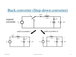
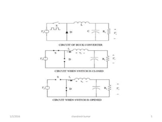
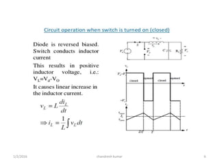
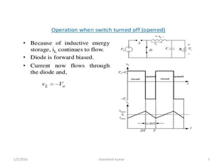
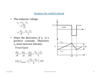
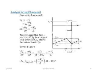
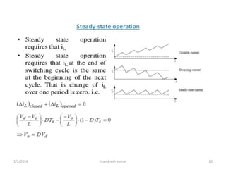
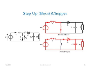
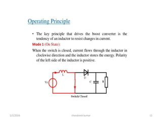
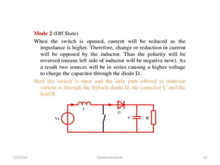
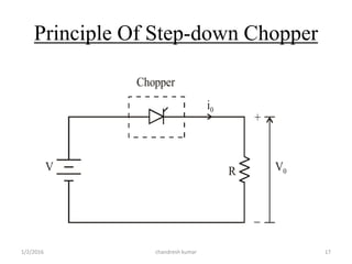
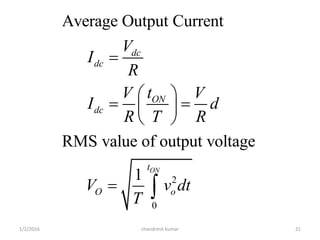
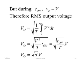
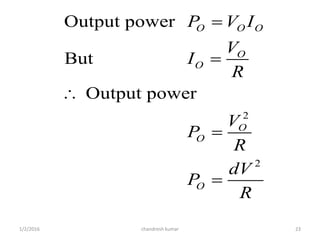
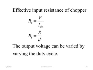
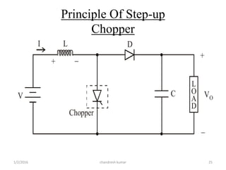
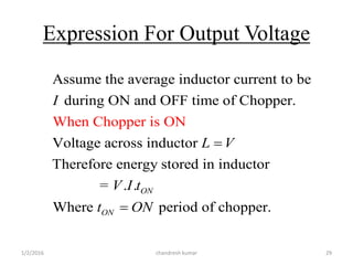
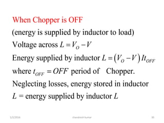
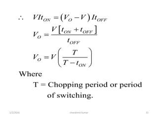
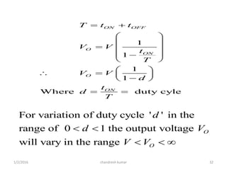
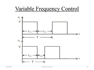
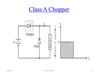
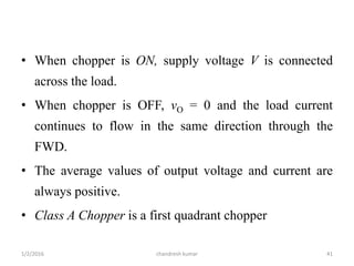
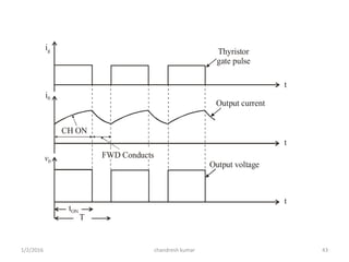
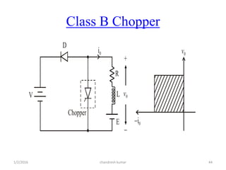
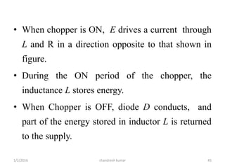
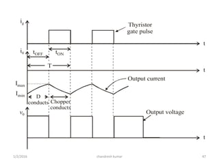
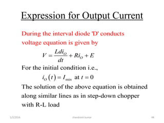
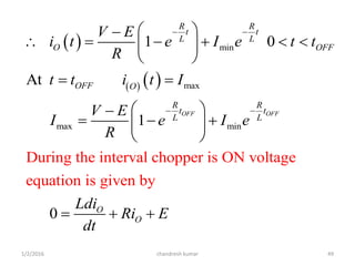
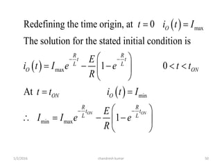
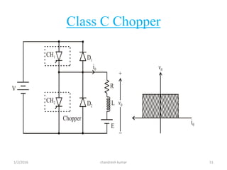
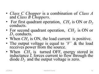
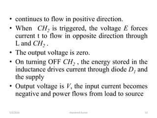
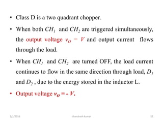
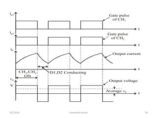
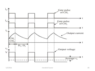
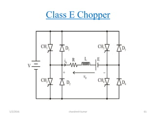
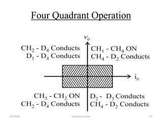
The document discusses different types of DC to DC converters known as choppers. It describes step-down and step-up choppers and how they produce output voltages lower and higher than the input voltage respectively. The principle of operation of step-down choppers involves using a thyristor switch to connect the input voltage across the load intermittently. Step-up choppers use an inductor to store energy when the switch is on and deliver it to the load and capacitor when the switch is off, boosting the voltage. The document also classifies choppers into different classes based on the polarity of output voltage and current.
in this PPT i gave introductions of the dc chopper . basic principle and working of dc chopper. and all the contents are in ps bimbhra power electronics book.
INTRODUCTION
A chopper is a static device which is used to obtain a variable dc voltage from a
constant dc voltage source. A chopper is also known as dc-to-dc converter. The thyristor converter offers greater efficiency, faster response, lower maintenance, smaller size and smooth control. Choppers are widely used in trolley cars, battery operated vehicles, traction motor control, control of large number of dc motors, etc….. They are also used in regenerative braking of dc motors to return energy back to supply and also as dc voltage regulators.
Choppers are of two types
• Step-down choppers
• Step-up choppers.
In step-down choppers, the output voltage will be less than the input voltage
whereas in step-up choppers output voltage will be more than the input voltage.
Classification of Choppers:
(a) Depending upon the direction of the output current and voltage, the converters can be classified into five classes namely Class A [One-quadrant Operation] Class B [One-quadrant Operation] Class C [Two-quadrant Operation] Class D [Two-quadrant Operation] Class E [Four-quadrant Operation]
(b) Based on the output voltage of the output, the choppers are classified as
(i) Step-Down Chopper In this case the average output voltage is less than the input voltage. It is also known as step down converter
(ii) Step-Up Chopper Here the average output voltage is more than the input voltage. It is also known as step up converter
(iii) Step-Up/Down Chopper This type of converter produces an output voltage that is either lower or higher than the input voltage
(c) Depending upon the power loss occurred during turn ON/OFF of the switching device, the choppers are classified into two categories namely
(i) Hard switched Converter Here the power loss is high during the switching (ON to OFF and OFF to ON) as a result of the non zero voltage and current on the power switches.
(ii) Soft switched or resonant converters In this type of choppers, the power loss is low at the time of switching as a result of zero voltage and/or zero current on the switches.
2
PRINCIPLE OF STEP-DOWN CHOPPER
Figure 2.1 shows a step-down chopper with resistive load. The thyristor in the
circuit acts as a switch. When thyristor is ON, supply voltage appears across the load and
when thyristor is OFF, the voltage across the load will be zero. The output voltage and
current waveforms are as shown in figure 2.2.
Principle of regenerative braking and chopper configurationAbhishek Choksi
A Regenerative Brake, is an energy recovery mechanism which slows a vehicle or object down by converting its kinetic energy into another form, which can be either used immediately or stored until needed.
Regenerative braking takes place whenever the speed of the motor exceeds the synchronous speed.
This braking method is called regenerative baking because here the motor works as generator and supply itself is given power from the load, i.e. motors.
Speed Control of Induction Motor using Variable Frequency DriveSandeep Kaushal
Induction motor is constant speed motor at a particular frequency and consumes almost same power irrespective of load demand. Let's talk about two different load one is high load and other low load. AT low load motor is delivering the load with some current and thereby torque is maintained. If load goes high, to maintain the same speed and developed torqued, motor will draw extra current and will corresponds to more losses. If speed of motor is reduced corresponding too low load and is increased corresponding to high load, then substantial amount of power can be saved. And speed can be changed by changing the frequency of input supply.
Do Diodes and electronic stuff freaks you out?And what about those clippers and clampers?The details are as follows.
You can learn every concept related to it here.Enjoy clipping :)
Power Electronics - Phase Controlled Converters.pptxPoornima D
A detailed analysis of the Controlled Converters with SCR. it contains a single-phase Fully controlled- Half Wave and Full Wave Rectifier with R, RL and RLC loads., Three Phase Fully controlled- Half Wave and Full Wave Rectifier with R, RL and RLC loads. Dual Converters. It also explains the effect of source inductance on the performance of converters
Chopper basically uses a Thyristor for high power applications. The process of turning off a conducting Thyristor is known as commutation. Here Thyristor is turned off by a current pulse that is why it is called a Current Commutated Chopper.
1.SINGLE PHASE HALF WAVE CONTROLLED CONVERTER WITH RESISTIVEINDUCTIVE LOAD
2 SINGLE PHASE FULLY CONTROLLED CONVERTER WITH RESISTIVEINDUCTIVE LOAD
3 SPEED CONTROL OF 3-PHASE SLIP RING (WOUND ROTOR) INDUCTION MOTOR
4 THYRISTORISED DRIVE FOR DC MOTOR WITH CLOSED LOOP CONTROL
5 THYRISTORISED DRIVE FOR PMDC MOTOR WITH SPEED MEASUREMENT & CLOSED LOOP CONTROL
6 SPEED MEASUREMENT OF PMDC MOTOR WITH CLOSED LOOP CONTROL
7 IGBT USING SINGLE 4 QUADRANT CHOPPER DRIVE FOR PMDC MOTOR WITH SPEED MEASUREMENT AND CLOSED LOOP AND CONTROL
8 SINGLE PHASE CYCLO CONVERTER BASED AC INDUCTION MOTOR CONTROLLER
9 THREE PHASE INPUT THYRISTORISED DRIVE 3HP DC MOTOR WITH CLOSED LOOP CONTROL
10 THREE PHASE INPUT IGBT DRIVE FOR 4 QUADRANT CHOPPER OF 3HP DC MOTOR WITH CLOSED LOOP CONTROL
ER Publication,
IJETR, IJMCTR,
Journals,
International Journals,
High Impact Journals,
Monthly Journal,
Good quality Journals,
Research,
Research Papers,
Research Article,
Free Journals, Open access Journals,
erpublication.org,
Engineering Journal,
Science Journals,
HEAP SORT ILLUSTRATED WITH HEAPIFY, BUILD HEAP FOR DYNAMIC ARRAYS.
Heap sort is a comparison-based sorting technique based on Binary Heap data structure. It is similar to the selection sort where we first find the minimum element and place the minimum element at the beginning. Repeat the same process for the remaining elements.
Saudi Arabia stands as a titan in the global energy landscape, renowned for its abundant oil and gas resources. It's the largest exporter of petroleum and holds some of the world's most significant reserves. Let's delve into the top 10 oil and gas projects shaping Saudi Arabia's energy future in 2024.
Forklift Classes Overview by Intella PartsIntella Parts
Discover the different forklift classes and their specific applications. Learn how to choose the right forklift for your needs to ensure safety, efficiency, and compliance in your operations.
For more technical information, visit our website https://intellaparts.com
Hybrid optimization of pumped hydro system and solar- Engr. Abdul-Azeez.pdffxintegritypublishin
Advancements in technology unveil a myriad of electrical and electronic breakthroughs geared towards efficiently harnessing limited resources to meet human energy demands. The optimization of hybrid solar PV panels and pumped hydro energy supply systems plays a pivotal role in utilizing natural resources effectively. This initiative not only benefits humanity but also fosters environmental sustainability. The study investigated the design optimization of these hybrid systems, focusing on understanding solar radiation patterns, identifying geographical influences on solar radiation, formulating a mathematical model for system optimization, and determining the optimal configuration of PV panels and pumped hydro storage. Through a comparative analysis approach and eight weeks of data collection, the study addressed key research questions related to solar radiation patterns and optimal system design. The findings highlighted regions with heightened solar radiation levels, showcasing substantial potential for power generation and emphasizing the system's efficiency. Optimizing system design significantly boosted power generation, promoted renewable energy utilization, and enhanced energy storage capacity. The study underscored the benefits of optimizing hybrid solar PV panels and pumped hydro energy supply systems for sustainable energy usage. Optimizing the design of solar PV panels and pumped hydro energy supply systems as examined across diverse climatic conditions in a developing country, not only enhances power generation but also improves the integration of renewable energy sources and boosts energy storage capacities, particularly beneficial for less economically prosperous regions. Additionally, the study provides valuable insights for advancing energy research in economically viable areas. Recommendations included conducting site-specific assessments, utilizing advanced modeling tools, implementing regular maintenance protocols, and enhancing communication among system components.
Cosmetic shop management system project report.pdfKamal Acharya
Buying new cosmetic products is difficult. It can even be scary for those who have sensitive skin and are prone to skin trouble. The information needed to alleviate this problem is on the back of each product, but it's thought to interpret those ingredient lists unless you have a background in chemistry.
Instead of buying and hoping for the best, we can use data science to help us predict which products may be good fits for us. It includes various function programs to do the above mentioned tasks.
Data file handling has been effectively used in the program.
The automated cosmetic shop management system should deal with the automation of general workflow and administration process of the shop. The main processes of the system focus on customer's request where the system is able to search the most appropriate products and deliver it to the customers. It should help the employees to quickly identify the list of cosmetic product that have reached the minimum quantity and also keep a track of expired date for each cosmetic product. It should help the employees to find the rack number in which the product is placed.It is also Faster and more efficient way.
Hierarchical Digital Twin of a Naval Power SystemKerry Sado
A hierarchical digital twin of a Naval DC power system has been developed and experimentally verified. Similar to other state-of-the-art digital twins, this technology creates a digital replica of the physical system executed in real-time or faster, which can modify hardware controls. However, its advantage stems from distributing computational efforts by utilizing a hierarchical structure composed of lower-level digital twin blocks and a higher-level system digital twin. Each digital twin block is associated with a physical subsystem of the hardware and communicates with a singular system digital twin, which creates a system-level response. By extracting information from each level of the hierarchy, power system controls of the hardware were reconfigured autonomously. This hierarchical digital twin development offers several advantages over other digital twins, particularly in the field of naval power systems. The hierarchical structure allows for greater computational efficiency and scalability while the ability to autonomously reconfigure hardware controls offers increased flexibility and responsiveness. The hierarchical decomposition and models utilized were well aligned with the physical twin, as indicated by the maximum deviations between the developed digital twin hierarchy and the hardware.
Student information management system project report ii.pdfKamal Acharya
Our project explains about the student management. This project mainly explains the various actions related to student details. This project shows some ease in adding, editing and deleting the student details. It also provides a less time consuming process for viewing, adding, editing and deleting the marks of the students.
6th International Conference on Machine Learning & Applications (CMLA 2024)ClaraZara1
6th International Conference on Machine Learning & Applications (CMLA 2024) will provide an excellent international forum for sharing knowledge and results in theory, methodology and applications of on Machine Learning & Applications.
Overview of the fundamental roles in Hydropower generation and the components involved in wider Electrical Engineering.
This paper presents the design and construction of hydroelectric dams from the hydrologist’s survey of the valley before construction, all aspects and involved disciplines, fluid dynamics, structural engineering, generation and mains frequency regulation to the very transmission of power through the network in the United Kingdom.
Author: Robbie Edward Sayers
Collaborators and co editors: Charlie Sims and Connor Healey.
(C) 2024 Robbie E. Sayers
1. DC TO DC
CONVERTER
Submitted to :
Er. Shimi S.L
(Assistant Professor)
Department of Electrical
Engineering , NITTTR Chandigarh
Presentation by:
Chandresh kumar
(141503)
ME-MOD-IC-2014
Department of Electrical engineering
NITTTR Chandigarh
chandresh kumar1/2/2016 1
2. Introduction
• Chopper is a static device.
• A variable dc voltage is obtained from a constant
dc voltage source.
• Also known as dc-to-dc converter.
• Widely used for motor control.
• Also used in regenerative braking.
• Thyristor (as a switch) converter offers greater
efficiency, faster response, lower maintenance,
smaller size and smooth control.
chandresh kumar1/2/2016 2
3. Types of Choppers
Step-down choppers.
Step-up choppers.
In step down chopper output voltage is less than
input voltage.
In step up chopper output voltage is more than
input voltage.
chandresh kumar1/2/2016 3
18. • A step-down chopper with resistive load.
• The thyristor in the circuit acts as a switch.
• When thyristor is ON, supply voltage appears
across the load
• When thyristor is OFF, the voltage across the
load will be zero.
chandresh kumar1/2/2016 18
19. Vdc
v0
V
V/R
i0
Idc
t
t
tON
T
tOFF
verage value of output or load voltage.
verage value of output or load current.
Time interval for which SCR conducts.
Time interval for which SCR is OFF.
Period of switching
dc
dc
ON
OFF
ON OFF
V A
I A
t
t
T t t
or chopping period.
1
Freq. of chopper switching or chopping freq.f
T
chandresh kumar1/2/2016 19
20. Average Output Voltage
.
duty cycle
ON
dc
ON OFF
ON
dc
ON
t
V V
t t
t
V V V d
T
t
but d
t
chandresh kumar1/2/2016 20
21. 2
0
Average Output Current
RMS value of output voltage
1 ON
dc
dc
ON
dc
t
O o
V
I
R
tV V
I d
R T R
V v dt
T
chandresh kumar1/2/2016 21
22. 2
0
2
But during ,
Therefore RMS output voltage
1
.
.
ON
ON o
t
O
ON
O ON
O
t v V
V V dt
T
tV
V t V
T T
V d V
chandresh kumar1/2/2016 22
23. 1/2/2016 chandresh kumar 23
2
2
Output power
But
Output power
O O O
O
O
O
O
O
P V I
V
I
R
V
P
R
dV
P
R
24. 1/2/2016 chandresh kumar 24
Effective input resistance of chopper
The output voltage can be varied by
varying the duty cycle.
i
dc
i
V
R
I
R
R
d
26. • The values of L and C are chosen depending
upon the requirement of output voltage and
current.
• The inductor current ‘I’ rises and the inductor
stores energy during the ON time of the
chopper, tON.
• Step-up chopper is used to obtain a load
voltage higher than the input voltage V.
• When the chopper is ON, the inductor L is
connected across the supply.
chandresh kumar1/2/2016 26
27. • The current tends to decrease resulting in
reversing the polarity of induced EMF in L.
• Therefore voltage across load is given by:-
• When the chopper is off, the inductor current I
is forced to flow through the diode D and load
for a period, tOFF.
chandresh kumar1/2/2016 27
. .,O O
dI
V V L i e V V
dt
28. • A large capacitor ‘C’ connected across the
load, will provide a continuous output voltage
• Diode D prevents any current flow from
capacitor to the source.
• Step up choppers are used for regenerative
braking of dc motors
1/2/2016 chandresh kumar 28
29. Expression For Output Voltage
1/2/2016 chandresh kumar 29
Assume the average inductor current to be
during ON and OFF time of Chopper.
Voltage across inductor
Therefore energy stored in inductor
= . .
Where
When Chopper
period of chopper.
is ON
ON
ON
I
L V
V I t
t ON
30. 1/2/2016 chandresh kumar 30
(energy is supplied by inductor to load)
Voltage across
Energy supplied by inductor
where period of Chopper.
Neg
When Chopper
lecting losses, energy stored in inductor
is OFF
O
O OFF
OFF
L V V
L V V It
t OFF
L
= energy supplied by inductor L
31. 1/2/2016 chandresh kumar 31
Where
T = Chopping period or period
of switching.
ON O OFF
ON OFF
O
OFF
O
ON
VIt V V It
V t t
V
t
T
V V
T t
32. 1/2/2016 chandresh kumar 32
1
1
1
1
Where duty cyle
ON OFF
O
ON
O
ON
T t t
V V
t
T
V V
d
t
d
T
For variation of duty cycle ' ' in the
range of 0 1 the output voltage
will vary in the range
O
O
d
d V
V V
33. Control Strategies
• The output dc voltage can be varied by the
following methods.
1. Pulse width modulation control or constant
frequency operation.
2. Variable frequency control
chandresh kumar1/2/2016 33
34. Pulse Width Modulation
• tON is varied keeping chopping frequency ‘f’ &
chopping period ‘T’ constant.
• Output voltage is varied by varying the ON
time tON
chandresh kumar1/2/2016 34
36. Variable Frequency Control
• Chopping frequency ‘f’ is varied keeping either
tON or tOFF constant.
• To obtain full output voltage range, frequency has
to be varied over a wide range.
• This method produces harmonics in the output
and for large tOFF load current may become
discontinuous
chandresh kumar1/2/2016 36
38. Performance Parameters
• The thyristor requires a certain minimum time
to turn ON and turn OFF.
• Duty cycle d can be varied only between a
min. & max. value, limiting the min. and max.
value of the output voltage.
• Ripple in the load current depends inversely on
the chopping frequency, f.
• To reduce the load ripple current, frequency
should be as high as possible.
chandresh kumar1/2/2016 38
39. Classification Of Choppers
• Choppers are classified as
– Class A Chopper
– Class B Chopper
– Class C Chopper
– Class D Chopper
– Class E Chopper
chandresh kumar1/2/2016 39
41. • When chopper is ON, supply voltage V is connected
across the load.
• When chopper is OFF, vO = 0 and the load current
continues to flow in the same direction through the
FWD.
• The average values of output voltage and current are
always positive.
• Class A Chopper is a first quadrant chopper
chandresh kumar1/2/2016 41
42. • Class A Chopper is a step-down chopper in which
power always flows form source to load.
• It is used to control the speed of dc motor.
• The output current equations obtained in step
down chopper with R-L load can be used to study
the performance of Class A Chopper.
chandresh kumar1/2/2016 42
45. • When chopper is ON, E drives a current through
L and R in a direction opposite to that shown in
figure.
• During the ON period of the chopper, the
inductance L stores energy.
• When Chopper is OFF, diode D conducts, and
part of the energy stored in inductor L is returned
to the supply.
chandresh kumar1/2/2016 45
46. • Average output voltage is positive.
• Average output current is negative.
• Therefore Class B Chopper operates in second
quadrant.
• In this chopper, power flows from load to source.
• Class B Chopper is used for regenerative braking of dc
motor.
• Class B Chopper is a step-up chopper.
chandresh kumar1/2/2016 46
48. Expression for Output Current
min
For the initial condition i.e.,
During the interval diode 'D' conduc
at 0
The solution of the ab
ts
voltage equation
ove equation is obtained
along similar lines as in s
is given by
O
O
O
Ldi
V Ri E
dt
i t I t
tep-down chopper
with R-L load
chandresh kumar1/2/2016 48
49.
min
max
max min
During the interval chopper is ON voltage
equation is g
1 0
At
1
0
iven by
OFF OFF
R R
t t
L L
O OFF
OFF O
R R
t t
L L
O
O
V E
i t e I e t t
R
t t i t I
V E
I e I e
R
Ldi
Ri E
dt
chandresh kumar1/2/2016 49
50.
max
max
min
min max
Redefining the time origin, at 0
The solution for the stated initial condition is
1 0
At
1
ON ON
O
R R
t t
L L
O ON
ON O
R R
t t
L L
t i t I
E
i t I e e t t
R
t t i t I
E
I I e e
R
chandresh kumar1/2/2016 50
52. • Class C Chopper is a combination of Class A
and Class B Choppers.
• For first quadrant operation, CH1 is ON or D2
conducts.
• For second quadrant operation, CH2 is ON or
D1 conducts.
• When CH1 is ON, the load current is positive.
• The output voltage is equal to ‘V’ & the load
receives power from the source.
• When CH1 is turned OFF, energy stored in
inductance L forces current to flow through the
diode D2 and the output voltage is zero.
chandresh kumar1/2/2016 52
53. • continues to flow in positive direction.
• When CH2 is triggered, the voltage E forces
current t to flow in opposite direction through
L and CH2 .
• The output voltage is zero.
• On turning OFF CH2 , the energy stored in the
inductance drives current through diode D1 and
the supply
• Output voltage is V, the input current becomes
negative and power flows from load to source
chandresh kumar1/2/2016 53
54. • Average output voltage is positive
• Average output current can take both positive
and negative values.
• Choppers CH1 & CH2 should not be turned
ON simultaneously as it would result in short
circuiting the supply.
• Class C Chopper can be used both for dc
motor control and regenerative braking of dc
motor.
• Class C Chopper can be used as a step-up or
step-down chopper.
chandresh kumar1/2/2016 54
55. Gate pulse
of CH2
Gate pulse
of CH1
Output current
Output voltage
ig1
ig2
i0
V0
t
t
t
t
D1 D1D2 D2CH1 CH2 CH1 CH2
ON ON ON ON
chandresh kumar1/2/2016 55
56. Class D Chopper
V
+ v0
D2
D1 CH2
CH1
v0
i0
L ER i0
chandresh kumar1/2/2016 56
57. • Class D is a two quadrant chopper.
• When both CH1 and CH2 are triggered simultaneously,
the output voltage vO = V and output current flows
through the load.
• When CH1 and CH2 are turned OFF, the load current
continues to flow in the same direction through load, D1
and D2 , due to the energy stored in the inductor L.
• Output voltage vO = - V.
chandresh kumar1/2/2016 57
58. • Average load voltage is positive if chopper
ON time is more than the OFF time
• Average output voltage becomes negative if
tON < tOFF .
• Hence the direction of load current is always
positive but load voltage can be positive or
negative.
chandresh kumar1/2/2016 58
59. Gate pulse
of CH2
Gate pulse
of CH1
Output current
Output voltage
Average v0
ig1
ig2
i0
v0
V
t
t
t
t
CH ,CH
ON
1 2 D1,D2 Conducting
chandresh kumar1/2/2016 59
60. Gate pulse
of CH2
Gate pulse
of CH1
Output current
Output voltage
Average v0
ig1
ig2
i0
v0
V
t
t
t
t
CH
CH
1
2
D , D1 2
chandresh kumar1/2/2016 60
62. Four Quadrant Operation
v0
i0
CH - CH ON
CH - D Conducts
1 4
4 2
D D2 3- Conducts
CH - D Conducts4 2
CH - CH ON
CH - D Conducts
3 2
2 4
CH - D Conducts
D - D Conducts
2 4
1 4
chandresh kumar1/2/2016 62
63. • Class E is a four quadrant chopper
• When CH1 and CH4 are triggered, output
current iO flows in positive direction through
CH1 and CH4, and with output voltage vO = V.
• This gives the first quadrant operation.
• When both CH1 and CH4 are OFF, the energy
stored in the inductor L drives iO through D2
and D3 in the same direction, but output
voltage vO = -V.
chandresh kumar1/2/2016 63
64. • Therefore the chopper operates in the fourth
quadrant.
• When CH2 and CH3 are triggered, the load
current iO flows in opposite direction & output
voltage vO = -V.
• Since both iO and vO are negative, the chopper
operates in third quadrant
chandresh kumar1/2/2016 64
65. • When both CH2 and CH3 are OFF, the load
current iO continues to flow in the same
direction D1 and D4 and the output voltage
vO = V.
• Therefore the chopper operates in second
quadrant as vO is positive but iO is negative.
chandresh kumar1/2/2016 65