Downloaded 692 times
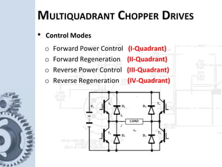

1) A chopper is used to provide variable DC voltage from a constant DC source and is widely used to control DC motors. 2) A chopper-fed DC drive works by connecting a DC chopper between a fixed-voltage DC source and DC motor to vary the armature voltage. 3) A multi-quadrant chopper drive can provide forward power control, forward regeneration, reverse power control, and reverse regeneration by controlling the switching of the thyristors in the chopper circuit.


