Download as PDF, PPTX


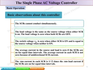


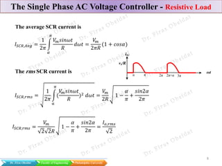
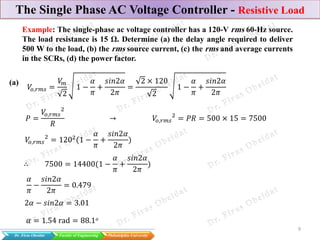


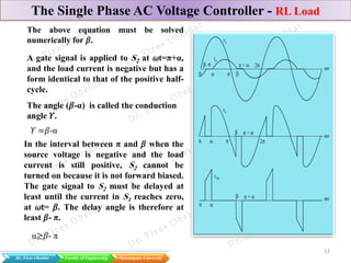
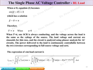
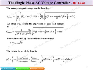


The document discusses various types of AC voltage controllers, specifically focusing on single-phase and three-phase configurations with resistive and RL loads. It details the basic operations, formulas, and calculations necessary for understanding how these converters manage voltage and power delivery. The document includes practical examples, showcasing the application of theoretical concepts in real-world scenarios.


