Download as PDF, PPTX
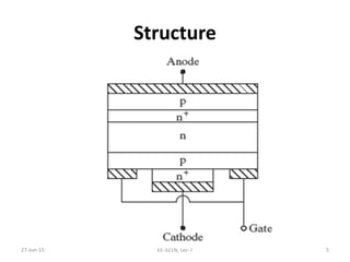
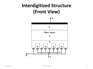
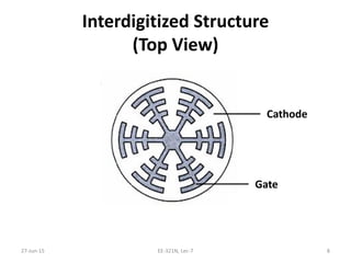
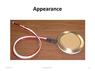
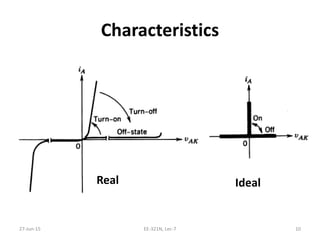

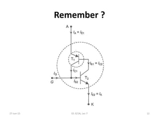
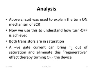
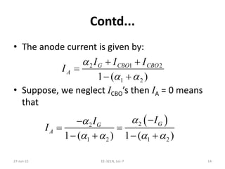


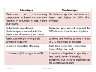


The document discusses the Gate Turn Off (GTO) thyristor. It is a fully controlled switching device that can be turned off through a negative gate current, unlike a conventional SCR which is only semi-controlled. GTOs provide ratings up to 6kV and 6kA. They have an interdigitated gate-cathode structure to ensure low access resistance and uniform turn-off. GTOs allow elimination of commutation components, faster switching, and improved converter efficiency but have higher conduction losses than SCRs.