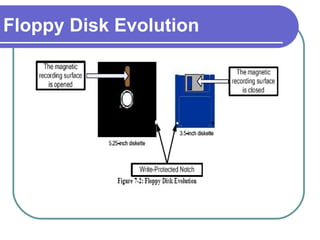
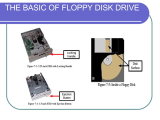
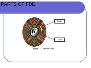
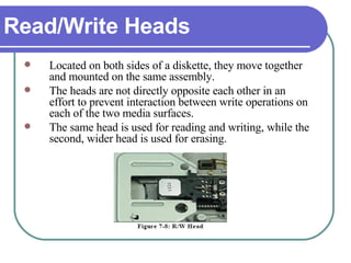
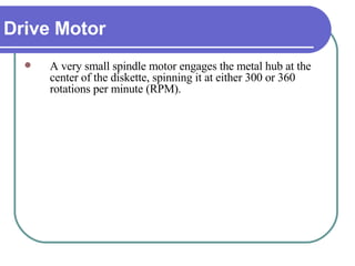
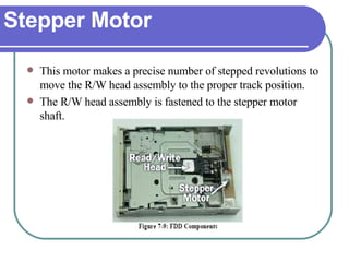
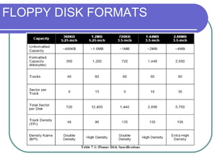
Chapter 7 BASIC DISK DRIVES
Objectives At the end of this chapter students should be able to: Learn the basic concept of FDD. Know how to handle FDD problems. Learn the basic concept of HDD. Know several types of HDD interfaces. Install and setup IDE drive. Understand and learn how run ScanDisk .
FLOPPY DISK DRIVE
Introduction Floppy disk drive (FDD)  is a device used to read and write data into  floppy disk  (also known as diskette).  It was originally created in 1967 by IBM. It was the primary means of storing data to a computer until the CD-ROM drive (will be covered in Chapter 8) became popular.  In fact, FDD have been a key component of most personal computers for more than 20 years and are still being used today.
Introduction
Floppy Disk Evolution The first floppy drives used an 8-inch disk, which evolved into the 5.25-inch disk that was used on the first IBM Personal Computer in August 1981.  The 5.25-inch disk held only 360 kilobytes compared to the 1.44 megabyte capacity of today's 3.5-inch diskette. By the mid-1990s, the 5.25-inch version had fallen out of popularity, partly because the diskette's recording surface could easily become contaminated by fingerprints through the open access area.
Floppy Disk Evolution
THE BASIC OF FLOPPY DISK DRIVE Basically, a floppy disk drive reads and writes (R/W) data to a small, circular piece of magnetic-coated plastic similar to audio cassette tape.  The FDD has an opening in the front to allow the floppy disk to be inserted and removed.  The R/W heads are open to the atmosphere. They touch and move directly on the surface of the diskette.  Older 5.25-inch units used a locking handles to secure the disk in the drive.  A spring-loaded assembly ejected the disk from the drive when the handle was rotated. Now, the 3.5-inch units have ejection buttons.
Data moves back and forth between the system’s memory and the floppy disk surface.  The system memory passes the data to the  Floppy Disk Controller (FDC)  and into the floppy drive’s control board. The control board converts the data into signals that can be applied to the drive’s R/W heads which, in turn, produce the magnetic spots on the disk surface. THE BASIC OF FLOPPY DISK DRIVE
In the original PCs, the FDC circuit was located on the FDD controller card (separated circuit from the mother board).  But now, all of this circuitry has been integrated into the motherboard itself. THE BASIC OF FLOPPY DISK DRIVE
THE BASIC OF FLOPPY DISK DRIVE
PARTS OF FDD Floppy disks are divided to parts called  tracks  which are arranged in concentric rings.  These tracks are then divided into  sector .  By having this technology, the system can jump from file “1” to “20” directly without having to fast forward from file “2” to “19”.  This is a similar approach used in Hard Disk Drive.
PARTS OF FDD
Major components of FDD  Read/Write Heads Drive Motor Stepper Motor Mechanical frame Circuit Board
Read/Write Heads Located on both sides of a diskette, they move together and mounted on the same assembly.  The heads are not directly opposite each other in an effort to prevent interaction between write operations on each of the two media surfaces.  The same head is used for reading and writing, while the second, wider head is used for erasing.
Drive Motor A very small spindle motor engages the metal hub at the center of the diskette, spinning it at either 300 or 360 rotations per minute (RPM).
Stepper Motor This motor makes a precise number of stepped revolutions to move the R/W head assembly to the proper track position.  The R/W head assembly is fastened to the stepper motor shaft.
Mechanical Frame A system of levers that opens the little protective window on the diskette to allow the R/W heads to touch the dual-sided diskette media.  An external button allows the diskette to be ejected, at which point the spring-loaded protective window on the diskette closes.
Circuit Board Contains all of the electronics to handle the data read from or written to the diskette. It also controls the stepper-motor control circuits used to move the R/W heads to each track, as well as the movement of the R/W heads toward the diskette surface.
FLOPPY DISK FORMATS Floppy disks often have two  capacity  specifications, which are the  unformatted capacity  and the  formatted capacity .  The capacities of different type of floppy disks are represented in the Table 7-1.
FLOPPY DISK FORMATS
The  density  of the disk surface refers to the amount of data that can be stored in a given amount of space. In other words, the higher the density, the tighter it can pack the data together on a floppy disk. There are two basic factors: How many tracks can be fit on the disk ( track density )   -measured in tracks per inch or  TPI How many bits can be fit on each track ( bit density ). - measured in bits per inch or  BPI . FLOPPY DISK FORMATS
KEEPING A FLOPPY DISK DRIVE RUNNING Floppy disk drives are inexpensive and easy to replace.  The only preventive maintenance required is to keep the floppy disk drive clean.  Excellent cleaning kits are available in most computer stores.  To achieve the best performance from a floppy disk drive in a high-use or industrial environment, schedule monthly cleaning.
If a floppy disk drive doesn’t work, the first thing you suspect should be the floppy disk. To check a floppy disk, follow the following procedure: First, make sure the disk is not write protected. The hole on the corner of a 3.5-inch disk should be closed. Try another disk. Try a new (formatted) disk. Try someone else's disk, the one that is known to work on another computer. If two or more disks are unreadable, the drive is suspected to have problem. ERROR CAUSED BY THE FLOPPY DISK
SRAM If you can read data from one disk, but not another, then the problem is the floppy disk.  Data errors on floppy disks generally result in an error message that ends with the words “Abort, Retry, Fail.”  The process for repairing floppy disks is identical to the process for repairing hard disk drives
CMOS SETTING Occasionally, the CMOS settings for floppy disks can cause problems with drive operations. Any of the following errors indicates a possible CMOS setup problem: General failure reading drive A: (or B:) Not ready error reading drive A: (or B:) Insert disk for drive A: (or B:) and press any key when ready .
FLOPPY DISK DRIVE CABLE PROBLEM Some of the problems with the FDD cables are; they are wear out, work themselves loose, and are sometimes improperly installed.  Check out both the data cable and the power cable as causes of the malfunctioning floppy disk drive before moving on to the controller. .
How to protect floppy disk Don’t use clip. don’t put near magnet, maybe data will lost don’ make any erasing on floppy disk Don’t put something heavy
HARD DISK DRIVE
Introduction Hard Disk  is the most popular storage device used to store various kinds of data in most computers.  Hard Disk Drive (HDD)  is the mechanism that controls positioning, reading, and writing data of the hard disk, which provide the largest amount of data storage for the PC. Although the hard disk drive and the hard disk are not the same thing, they are packaged as a unit and so either term is sometimes used to refer to the whole unit.
HARD DISK DRIVE BASIC Hard disks were invented in the 1950s. They started as large disks up to 20 inches in diameter holding just a few megabytes.  They were originally called as “fixed disks”, but later became known as “hard disks” to distinguish them from “floppy disks”. Hard disks have a  hard platter  that holds the magnetic medium, as opposed to the flexible plastic film found in tapes and floppies. Both hard disks and floppy disks use the same  magnetic  recording techniques.
HDD CHARACTERISTIC Capacity of a hard disk drive is usually quoted in  gigabytes .  Older HDDs used to quote their smaller capacities in megabytes.  The physical size of a hard disk drive is measured in inches. The majority of HDDs used in desktops today are 3.5-inch wide, while those used in laptops are 2.5-inch wide.
HDD CHARACTERISTIC
NON-VOLATILE MEMORY Basically, a hard disk consists of flat disks called  platters , coated on both sides with a special magnetic media material designed to store data.  The platters are mounted by cutting a hole in the center and stacking them onto a  spindle .  The platters rotate at high speed, driven by a special  spindle motor  connected to the spindle. Special electromagnetic R/W devices called R/W heads  are mounted onto  sliders  and used to either record data onto the disk or read data from it. The sliders are mounted onto  arms , all of which are mechanically connected into a single assembly and positioned over the surface of the disk by a device called an  actuator .
NON-VOLATILE MEMORY A  logic board  controls the activity of the other components and communicates with the rest of the PC. Each surface of each platter on the disk can hold tens of billions of individual bits of data. These are organized into larger “chunks” for convenience, and to allow for easier and faster access to information stored in the hard disks. Each platter has two heads, one on the top of the platter and one on the bottom (see Figure 7-15). In that case, a hard disk with two platters has four surfaces and six total heads, while a hard disk with three platters has six surfaces and six total heads.
NON-VOLATILE MEMORY
ROM Each platter has its information recorded in concentric circles called  tracks . Each track is   further broken down into smaller pieces called  sectors , each of which holds 512 bytes of information.  Sectors are not read individually on most PCs, but they are grouped together into continuous chunks called  clusters .  Since there are corresponding tracks on the top and bottom of each disk in the stack, the HDD controller organizes them into  cylinders .
ROM For example, Cylinder X of a four platter HDD would consist of Track X of each surface. The cylinder concept is described Figure 7-17.
TYPES OF ROM There are four basic ROM types: Programmable ROM (PROM) Erasable Programmable ROM (EPROM) Electrically Erasable Programmable ROM (EEPROM) Flash memory
HARD DISK INTERFACES Interface  is a communication channel between the hard disk and the system, which handles all the data flows that is read from or written to the hard disk. Below are some of hard disk drive interfaces: ST-506 ESDI SCSI IDE/ATA SATA
IDE DRIVE INSTALLATION AND SETUP There are 5 basic steps of installing a hard disk drive. Setting the jumpers. Mounting the hard drive. Connecting the cable. Plugging in the power connector. Configuring the drive.
SETTING THE JUMPERS There are usually only a few jumper settings (shown on the HDD casing surface) and they do not vary greatly from drive to drive. Here are the jumper’s settings you will normally find in a hard disk.
MOUNTING THE HARD DRIVE The simplest way to mount hard disks into the  system case  is the direct mounting method, where the disk is screwed directly into a drive bay.
CONNECTING THE CABLE AND POWER CONNECTOR IDE devices use a ribbon cable to connect to each other.  IDE ribbon cables have either 40 or 80 wires.  The three connectors are typically different colors and attach to specific items: The black connector attaches to the primary ( master ) drive. The grey connector attaches to the secondary ( slave ) drive. The blue connector attaches to the motherboard.
CONNECTING THE CABLE AND POWER CONNECTOR
CONNECTING THE CABLE AND POWER CONNECTOR Assuming that, you want to connect 2 hard drives to your computer system. You have done the jumper setting for your master and slave drive. Follow these steps:
STEP 1 1. Connect the black-coloured connector to the master drive.
STEP 2 2. Connect the grey-coloured connector to the slave drive.
3. Connect the blue connector to the primary IDE controller on the motherboard STEP 3
STEP 4 After all of the data cables have been connected, connect power cables to all of the drives. You will need to push firmly to make sure that the power cable is properly seated in the socket of the drive.
CONFIGURING THE DRIVE Before setting up the operating system on the computer, it is important that the BIOS settings are set correctly. To enter the BIOS, follow the instructions on the POST screen.
STEP 1 On the POST (Power-on Self Test) screen shown in Figure 7- 35, it says “Press Del to enter Setup”. Other computers may  ask you to hit Ctrl+Alt+Esc, or hit F1. Press the button  “ Delete” on the keyboard.
STEP 2 You should see the main BIOS selection menu. At all times, use the arrow keys (Up, Down, Left and Right) to navigate between the items and using the ENTER key to select the item.  Select Standard CMOS Features and press ENTER. You should see your current C: drive settings under the primary hard drive (master).
STEP 2
STEP 3 Go on to the configuration of the primary hard drive (slave). Your BIOS should auto detect your new hard drive and give you its settings.
STEP 4 Once you're done with the BIOS configuration, select the Save & Exit Setup at the BIOS main menu screen and allow the system to reboot.  Or, you can just simply press the button F10 on the keyboard.
STEP 4
ScanDisk  is a utility in MS-DOS and Microsoft Windows systems which checks and repairs file systems and bad clusters.  It was introduced in MS-DOS version 6.2.  Previous versions of MS-DOS supplied only the simpler, purely text-based program CHKDSK. SCANDISK
Double-click  My Computer , and then right-click the hard disk drive that you want to check. Click  Properties , and then click  Tools . Under  Error-checking , click the  Check Now  button. A dialog box that shows the Check disk options will appear RUNNING CHKDSK
RUNNING CHKDSK
RUNNING CHKDSK
Use one of the following procedures: To run CHKDSK in read-only mode, click Start. To repair errors without scanning the volume for bad sectors, select the  Automatically fix file system errors  check box, and then click  Start . To repair errors, locate bad sectors, and recover readable information, select the  Scan for and attempt recovery of bad sectors  check box, and then click  Start . RUNNING CHKDSK
RUNNING CHKDSK

Chapter 7: Basic Disk Drives

  • 1.
    Chapter 7 BASICDISK DRIVES
  • 2.
    Objectives At theend of this chapter students should be able to: Learn the basic concept of FDD. Know how to handle FDD problems. Learn the basic concept of HDD. Know several types of HDD interfaces. Install and setup IDE drive. Understand and learn how run ScanDisk .
  • 3.
  • 4.
    Introduction Floppy diskdrive (FDD) is a device used to read and write data into floppy disk (also known as diskette). It was originally created in 1967 by IBM. It was the primary means of storing data to a computer until the CD-ROM drive (will be covered in Chapter 8) became popular. In fact, FDD have been a key component of most personal computers for more than 20 years and are still being used today.
  • 5.
  • 6.
    Floppy Disk EvolutionThe first floppy drives used an 8-inch disk, which evolved into the 5.25-inch disk that was used on the first IBM Personal Computer in August 1981. The 5.25-inch disk held only 360 kilobytes compared to the 1.44 megabyte capacity of today's 3.5-inch diskette. By the mid-1990s, the 5.25-inch version had fallen out of popularity, partly because the diskette's recording surface could easily become contaminated by fingerprints through the open access area.
  • 7.
  • 8.
    THE BASIC OFFLOPPY DISK DRIVE Basically, a floppy disk drive reads and writes (R/W) data to a small, circular piece of magnetic-coated plastic similar to audio cassette tape. The FDD has an opening in the front to allow the floppy disk to be inserted and removed. The R/W heads are open to the atmosphere. They touch and move directly on the surface of the diskette. Older 5.25-inch units used a locking handles to secure the disk in the drive. A spring-loaded assembly ejected the disk from the drive when the handle was rotated. Now, the 3.5-inch units have ejection buttons.
  • 9.
    Data moves backand forth between the system’s memory and the floppy disk surface. The system memory passes the data to the Floppy Disk Controller (FDC) and into the floppy drive’s control board. The control board converts the data into signals that can be applied to the drive’s R/W heads which, in turn, produce the magnetic spots on the disk surface. THE BASIC OF FLOPPY DISK DRIVE
  • 10.
    In the originalPCs, the FDC circuit was located on the FDD controller card (separated circuit from the mother board). But now, all of this circuitry has been integrated into the motherboard itself. THE BASIC OF FLOPPY DISK DRIVE
  • 11.
    THE BASIC OFFLOPPY DISK DRIVE
  • 12.
    PARTS OF FDDFloppy disks are divided to parts called tracks which are arranged in concentric rings. These tracks are then divided into sector . By having this technology, the system can jump from file “1” to “20” directly without having to fast forward from file “2” to “19”. This is a similar approach used in Hard Disk Drive.
  • 13.
  • 14.
    Major components ofFDD Read/Write Heads Drive Motor Stepper Motor Mechanical frame Circuit Board
  • 15.
    Read/Write Heads Locatedon both sides of a diskette, they move together and mounted on the same assembly. The heads are not directly opposite each other in an effort to prevent interaction between write operations on each of the two media surfaces. The same head is used for reading and writing, while the second, wider head is used for erasing.
  • 16.
    Drive Motor Avery small spindle motor engages the metal hub at the center of the diskette, spinning it at either 300 or 360 rotations per minute (RPM).
  • 17.
    Stepper Motor Thismotor makes a precise number of stepped revolutions to move the R/W head assembly to the proper track position. The R/W head assembly is fastened to the stepper motor shaft.
  • 18.
    Mechanical Frame Asystem of levers that opens the little protective window on the diskette to allow the R/W heads to touch the dual-sided diskette media. An external button allows the diskette to be ejected, at which point the spring-loaded protective window on the diskette closes.
  • 19.
    Circuit Board Containsall of the electronics to handle the data read from or written to the diskette. It also controls the stepper-motor control circuits used to move the R/W heads to each track, as well as the movement of the R/W heads toward the diskette surface.
  • 20.
    FLOPPY DISK FORMATSFloppy disks often have two capacity specifications, which are the unformatted capacity and the formatted capacity . The capacities of different type of floppy disks are represented in the Table 7-1.
  • 21.
  • 22.
    The density of the disk surface refers to the amount of data that can be stored in a given amount of space. In other words, the higher the density, the tighter it can pack the data together on a floppy disk. There are two basic factors: How many tracks can be fit on the disk ( track density ) -measured in tracks per inch or TPI How many bits can be fit on each track ( bit density ). - measured in bits per inch or BPI . FLOPPY DISK FORMATS
  • 23.
    KEEPING A FLOPPYDISK DRIVE RUNNING Floppy disk drives are inexpensive and easy to replace. The only preventive maintenance required is to keep the floppy disk drive clean. Excellent cleaning kits are available in most computer stores. To achieve the best performance from a floppy disk drive in a high-use or industrial environment, schedule monthly cleaning.
  • 24.
    If a floppydisk drive doesn’t work, the first thing you suspect should be the floppy disk. To check a floppy disk, follow the following procedure: First, make sure the disk is not write protected. The hole on the corner of a 3.5-inch disk should be closed. Try another disk. Try a new (formatted) disk. Try someone else's disk, the one that is known to work on another computer. If two or more disks are unreadable, the drive is suspected to have problem. ERROR CAUSED BY THE FLOPPY DISK
  • 25.
    SRAM If youcan read data from one disk, but not another, then the problem is the floppy disk. Data errors on floppy disks generally result in an error message that ends with the words “Abort, Retry, Fail.” The process for repairing floppy disks is identical to the process for repairing hard disk drives
  • 26.
    CMOS SETTING Occasionally,the CMOS settings for floppy disks can cause problems with drive operations. Any of the following errors indicates a possible CMOS setup problem: General failure reading drive A: (or B:) Not ready error reading drive A: (or B:) Insert disk for drive A: (or B:) and press any key when ready .
  • 27.
    FLOPPY DISK DRIVECABLE PROBLEM Some of the problems with the FDD cables are; they are wear out, work themselves loose, and are sometimes improperly installed. Check out both the data cable and the power cable as causes of the malfunctioning floppy disk drive before moving on to the controller. .
  • 28.
    How to protectfloppy disk Don’t use clip. don’t put near magnet, maybe data will lost don’ make any erasing on floppy disk Don’t put something heavy
  • 29.
  • 30.
    Introduction Hard Disk is the most popular storage device used to store various kinds of data in most computers. Hard Disk Drive (HDD) is the mechanism that controls positioning, reading, and writing data of the hard disk, which provide the largest amount of data storage for the PC. Although the hard disk drive and the hard disk are not the same thing, they are packaged as a unit and so either term is sometimes used to refer to the whole unit.
  • 31.
    HARD DISK DRIVEBASIC Hard disks were invented in the 1950s. They started as large disks up to 20 inches in diameter holding just a few megabytes. They were originally called as “fixed disks”, but later became known as “hard disks” to distinguish them from “floppy disks”. Hard disks have a hard platter that holds the magnetic medium, as opposed to the flexible plastic film found in tapes and floppies. Both hard disks and floppy disks use the same magnetic recording techniques.
  • 32.
    HARD DISK DRIVEBASIC Hard disks were invented in the 1950s. They started as large disks up to 20 inches in diameter holding just a few megabytes. They were originally called as “fixed disks”, but later became known as “hard disks” to distinguish them from “floppy disks”. Hard disks have a hard platter that holds the magnetic medium, as opposed to the flexible plastic film found in tapes and floppies. Both hard disks and floppy disks use the same magnetic recording techniques.
  • 33.
    HDD CHARACTERISTIC Capacityof a hard disk drive is usually quoted in gigabytes . Older HDDs used to quote their smaller capacities in megabytes. The physical size of a hard disk drive is measured in inches. The majority of HDDs used in desktops today are 3.5-inch wide, while those used in laptops are 2.5-inch wide.
  • 34.
  • 35.
    NON-VOLATILE MEMORY Basically,a hard disk consists of flat disks called platters , coated on both sides with a special magnetic media material designed to store data. The platters are mounted by cutting a hole in the center and stacking them onto a spindle . The platters rotate at high speed, driven by a special spindle motor connected to the spindle. Special electromagnetic R/W devices called R/W heads are mounted onto sliders and used to either record data onto the disk or read data from it. The sliders are mounted onto arms , all of which are mechanically connected into a single assembly and positioned over the surface of the disk by a device called an actuator .
  • 36.
    NON-VOLATILE MEMORY A logic board controls the activity of the other components and communicates with the rest of the PC. Each surface of each platter on the disk can hold tens of billions of individual bits of data. These are organized into larger “chunks” for convenience, and to allow for easier and faster access to information stored in the hard disks. Each platter has two heads, one on the top of the platter and one on the bottom (see Figure 7-15). In that case, a hard disk with two platters has four surfaces and six total heads, while a hard disk with three platters has six surfaces and six total heads.
  • 37.
  • 38.
    ROM Each platterhas its information recorded in concentric circles called tracks . Each track is further broken down into smaller pieces called sectors , each of which holds 512 bytes of information. Sectors are not read individually on most PCs, but they are grouped together into continuous chunks called clusters . Since there are corresponding tracks on the top and bottom of each disk in the stack, the HDD controller organizes them into cylinders .
  • 39.
    ROM For example,Cylinder X of a four platter HDD would consist of Track X of each surface. The cylinder concept is described Figure 7-17.
  • 40.
    TYPES OF ROMThere are four basic ROM types: Programmable ROM (PROM) Erasable Programmable ROM (EPROM) Electrically Erasable Programmable ROM (EEPROM) Flash memory
  • 41.
    HARD DISK INTERFACESInterface is a communication channel between the hard disk and the system, which handles all the data flows that is read from or written to the hard disk. Below are some of hard disk drive interfaces: ST-506 ESDI SCSI IDE/ATA SATA
  • 42.
    IDE DRIVE INSTALLATIONAND SETUP There are 5 basic steps of installing a hard disk drive. Setting the jumpers. Mounting the hard drive. Connecting the cable. Plugging in the power connector. Configuring the drive.
  • 43.
    SETTING THE JUMPERSThere are usually only a few jumper settings (shown on the HDD casing surface) and they do not vary greatly from drive to drive. Here are the jumper’s settings you will normally find in a hard disk.
  • 44.
    MOUNTING THE HARDDRIVE The simplest way to mount hard disks into the system case is the direct mounting method, where the disk is screwed directly into a drive bay.
  • 45.
    CONNECTING THE CABLEAND POWER CONNECTOR IDE devices use a ribbon cable to connect to each other. IDE ribbon cables have either 40 or 80 wires. The three connectors are typically different colors and attach to specific items: The black connector attaches to the primary ( master ) drive. The grey connector attaches to the secondary ( slave ) drive. The blue connector attaches to the motherboard.
  • 46.
    CONNECTING THE CABLEAND POWER CONNECTOR
  • 47.
    CONNECTING THE CABLEAND POWER CONNECTOR Assuming that, you want to connect 2 hard drives to your computer system. You have done the jumper setting for your master and slave drive. Follow these steps:
  • 48.
    STEP 1 1.Connect the black-coloured connector to the master drive.
  • 49.
    STEP 2 2.Connect the grey-coloured connector to the slave drive.
  • 50.
    3. Connect theblue connector to the primary IDE controller on the motherboard STEP 3
  • 51.
    STEP 4 Afterall of the data cables have been connected, connect power cables to all of the drives. You will need to push firmly to make sure that the power cable is properly seated in the socket of the drive.
  • 52.
    CONFIGURING THE DRIVEBefore setting up the operating system on the computer, it is important that the BIOS settings are set correctly. To enter the BIOS, follow the instructions on the POST screen.
  • 53.
    STEP 1 Onthe POST (Power-on Self Test) screen shown in Figure 7- 35, it says “Press Del to enter Setup”. Other computers may ask you to hit Ctrl+Alt+Esc, or hit F1. Press the button “ Delete” on the keyboard.
  • 54.
    STEP 2 Youshould see the main BIOS selection menu. At all times, use the arrow keys (Up, Down, Left and Right) to navigate between the items and using the ENTER key to select the item. Select Standard CMOS Features and press ENTER. You should see your current C: drive settings under the primary hard drive (master).
  • 55.
  • 56.
    STEP 3 Goon to the configuration of the primary hard drive (slave). Your BIOS should auto detect your new hard drive and give you its settings.
  • 57.
    STEP 4 Onceyou're done with the BIOS configuration, select the Save & Exit Setup at the BIOS main menu screen and allow the system to reboot. Or, you can just simply press the button F10 on the keyboard.
  • 58.
  • 59.
    ScanDisk isa utility in MS-DOS and Microsoft Windows systems which checks and repairs file systems and bad clusters. It was introduced in MS-DOS version 6.2. Previous versions of MS-DOS supplied only the simpler, purely text-based program CHKDSK. SCANDISK
  • 60.
    Double-click MyComputer , and then right-click the hard disk drive that you want to check. Click Properties , and then click Tools . Under Error-checking , click the Check Now button. A dialog box that shows the Check disk options will appear RUNNING CHKDSK
  • 61.
  • 62.
  • 63.
    Use one ofthe following procedures: To run CHKDSK in read-only mode, click Start. To repair errors without scanning the volume for bad sectors, select the Automatically fix file system errors check box, and then click Start . To repair errors, locate bad sectors, and recover readable information, select the Scan for and attempt recovery of bad sectors check box, and then click Start . RUNNING CHKDSK
  • 64.