Downloaded 109 times

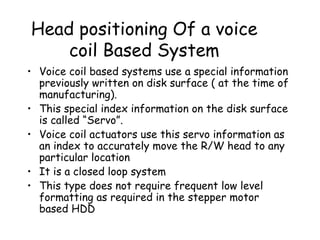
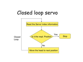
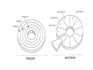
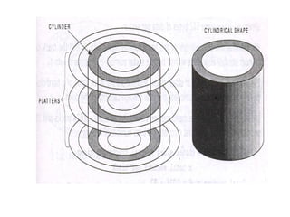
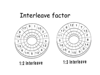
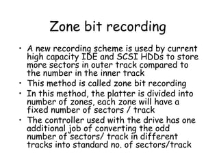
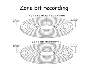
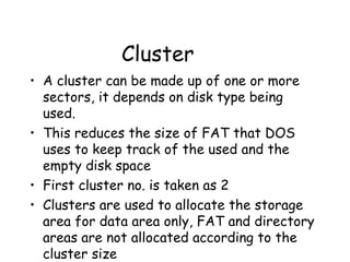

The document discusses the different components and technologies used in hard disk drives for head positioning and data storage. It covers voice coil actuators, servo information, closed-loop positioning, wedge, embedded and dedicated servo types. It also describes disk geometry concepts like tracks, sectors, cylinders and calculates storage capacity. Technologies like interleave, zone bit recording, write pre-compensation, master boot record, clusters, logical vs physical formatting are summarized.


