Floppy Disk Drive
•The floppy disk drive (FDD) was the primary
means of adding data to a computer until the
CD-ROM drive became popular.
• Basically, a floppy disk drive reads and writes
data to a small, circular piece of metal-coated
plastic similar to audio cassette tape.
3.
FDD contd..
• Thefloppy disk drive (FDD) was invented at
IBM by Alan Shugart in 1967.
• Floppy disk drives had five generations: 360
KB (5 ¼”), 1.2 MB (5 ¼”), 720 KB (3 ½”), 1.44
MB (3 ½”) and 2.88 MB (3 ½”).
• The 5.25-inch disks were dubbed "floppy"
because the diskette packaging was a very
flexible plastic envelope.
4.
FDD Contd..
A floppydisk is a lot like a cassette tape:
• Both use a thin plastic base material coated
with iron oxide. This oxide is a ferromagnetic
material, meaning that if you expose it to a
magnetic field it is permanently magnetized
by the field.
• Both can record information instantly.
• Both can be erased and reused many times.
• Both are very inexpensive and easy to use.
5.
FDD Contd..
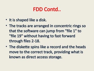
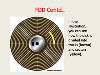
• Itis shaped like a disk.
• The tracks are arranged in concentric rings so
that the software can jump from "file 1" to
"file 19" without having to fast forward
through files 2-18.
• The diskette spins like a record and the heads
move to the correct track, providing what is
known as direct access storage.
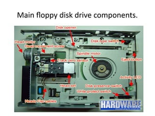
FDD Major Parts
•Read/Write Heads: Located on both sides of a
diskette, they move together on the same
assembly.
• The same head is used for reading and writing,
while a second, wider head is used for erasing
a track just prior to it being written.
8.
FDD Major Parts
•Drive Motor: A very small spindle motor
engages the metal hub at the center of the
diskette, spinning it at either 300 or 360
rotations per minute (RPM).
9.
FDD Major Parts
•Stepper Motor: This motor makes a precise
number of stepped revolutions to move the
read/write head assembly to the proper track
position. The read/write head assembly is
fastened to the stepper motor shaft.
10.
FDD Major Parts
•Mechanical Frame: A system of levers that
opens the little protective window on the
diskette to allow the read/write heads to
touch the dual-sided diskette media.
• An external button allows the diskette to be
ejected, at which point the spring-loaded
protective window on the diskette closes.
11.
FDD Major Parts
•Circuit Board: Contains all of the electronics to
handle the data read from or written to the
diskette. It also controls the stepper-motor
control circuits used to move the read/write
heads to each track, as well as the movement
of the read/write heads toward the diskette
surface.
4 Sensors onFDD
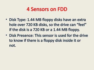
• Disk Type: 1.44 MB floppy disks have an extra
hole over 720 KB disks, so the drive can “feel”
if the disk is a 720 KB or a 1.44 MB floppy.
• Disk Presence: This sensor is used for the drive
to know if there is a floppy disk inside it or
not.
15.
4 Sensors onFDD
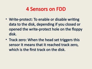
• Write-protect: To enable or disable writing
data to the disk, depending if you closed or
opened the write-protect hole on the floppy
disk.
• Track zero: When the head set triggers this
sensor it means that it reached track zero,
which is the first track on the disk.
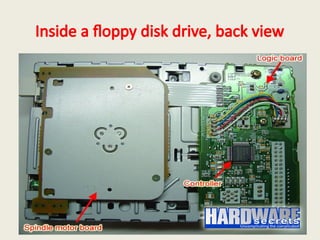
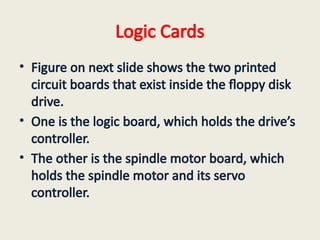
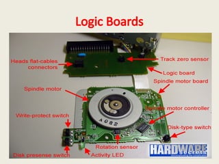
Logic Cards
• Figureon next slide shows the two printed
circuit boards that exist inside the floppy disk
drive.
• One is the logic board, which holds the drive’s
controller.
• The other is the spindle motor board, which
holds the spindle motor and its servo
controller.
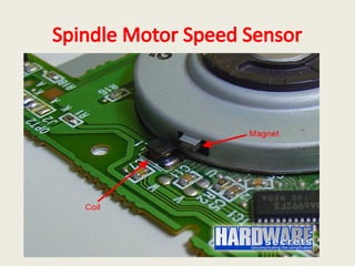
Motor Speed Sensor
•The spindle motor uses a sensor for checking
if it is rotating or not and also to check its
speed.
• So, this motor is a closed loop system, i.e. it
has a sensor that feeds the controller in order
to perform any speed adjustments that may
be necessary to keep it rotating at its correct
speed.
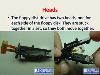
Heads
• The floppydisk drive has two heads, one for
each side of the floppy disk. They are stuck
together in a set, so they both move together.
22.
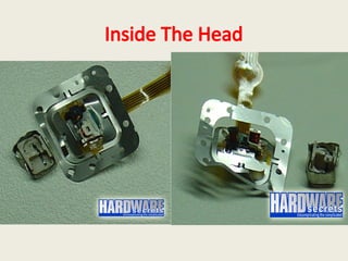
Inside The Head
•it has two coils inside. These coils are in
charge of generating the necessary
electromagnetic field for erasing or writing
data on the disk and also in charge of
capturing the magnetic field generated by the
floppy and transforming it into electrical
current when data is being read from the
floppy.
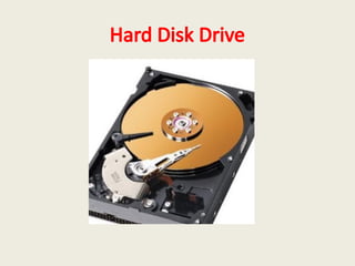
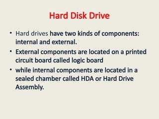
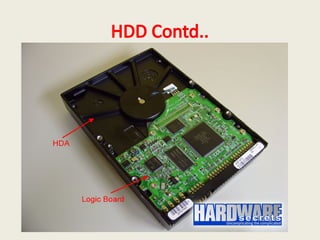
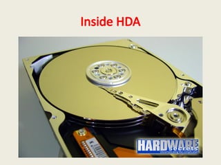
Hard Disk Drive
•Hard drives have two kinds of components:
internal and external.
• External components are located on a printed
circuit board called logic board
• while internal components are located in a
sealed chamber called HDA or Hard Drive
Assembly.
HDD Contd..
• Youcannot open a hard drive or you will make
your drive unusable. Hard drives are
assembled in clean rooms (cleaner than
surgery rooms) and then sealed.
• Any particle of dust inside the HDA can
destroy the surface of the discs, because the
discs spin at a very high speed (at least 7,200
rpm nowadays).
28.
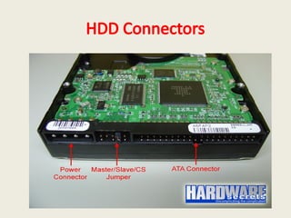
HDD Connectors
• Harddisk drives have basically two connectors,
one for power and other for exchanging data
with the computer. This second connector is
better known as “interface”.
• The two common interfaces are called ATA
(Advanced Technology Attachment) and SATA
(Serial ATA).
• Later interface was created to replace ATA and is
becoming more popular these days.
29.
HDD Connectors
• Afterthe released of SATA, ATA interface
started being also called PATA (Parallel ATA).
• Another famous interface is called SCSI (Small
Computer Systems Interface), but it is targeted
to servers and rarely seen on PCs targeted to
end-users.
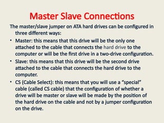
Master Slave Connections
Themaster/slave jumper on ATA hard drives can be configured in
three different ways:
• Master: this means that this drive will be the only one
attached to the cable that connects the hard drive to the
computer or will be the first drive in a two-drive configuration.
• Slave: this means that this drive will be the second drive
attached to the cable that connects the hard drive to the
computer.
• CS (Cable Select): this means that you will use a “special”
cable (called CS cable) that the configuration of whether a
drive will be master or slave will be made by the position of
the hard drive on the cable and not by a jumper configuration
on the drive.
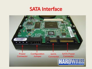
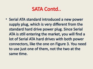
SATA Contd..
• SerialATA standard introduced a new power
supply plug, which is very different from the
standard hard drive power plug. Since Serial
ATA is still entering the market, you will find a
lot of Serial ATA hard drives with both power
connectors, like the one on Figure 3. You need
to use just one of them, not the two at the
same time.
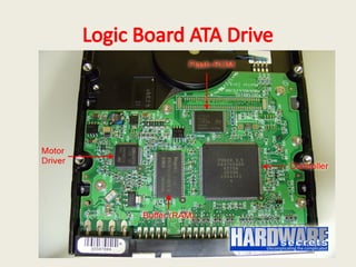
Controller
• The bigcircuit is the controller. It is in charge
of everything: exchanging data between the
hard drive and the computer, controlling the
motors on the hard drive, commanding the
heads to read or write data, etc
37.
FLASH ROM
• Optionallythere is a Flash-ROM circuit where
the hard drive firmware is located. Firmware is
the name given to a program that is stored
inside a ROM (Read Only Memory). The hard
drive firmware is the program its controller
executes. Sometimes this device is embedded
in the controller
38.
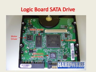
MOTOR Driver Chip
•The controller doesn’t drive enough current to
turn on or move the hard drive motors. So all
hard drives use a motor driver chip. This chip
is a current amplifier. It takes the commands
sent from the controller to the motors and
passes them to the motors, but with a higher
current. So, this chip is located between the
controller and the motors.
39.
RAM
• The fourthmain chip you can find on a logic
board is the RAM (Random Access Memory)
chip, also known as buffer. This chips has an
ultimate role in the hard drive performance.
The higher its capacity, the fastest the data
transfer between the drive and the computer
will be. You can find out the capacity of your
hard drive buffer on the chip manufacturer’s
website.
40.
SATA/ ATA ConverterChip
• A lot of manufacturers instead of designing
Serial ATA controller chips simply pick ATA
controller chips and add a converter chip to
convert the hard drive Serial ATA interface into
regular ATA.
41.
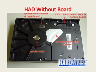
Spindle Motor
• Onnext slide is the H.DA after the logic board
is removed. There you can clearly see the
spindle motor and its contacts – which
connect this motor to the logic board –, and
also the contacts from the devices inside the
HDA, namely the heads and the voice coil
actuators.
Spindle Motor
• Onhard drives targeted to desktops, the
spindle motor rotates at 5,400 rpm, 7,200 rpm
or even 10,000 rpm, depending on the drive.
The faster this motor rotates, the faster data
can be read from the platters. Hard drives
targeted to laptops usually rotates at 4,200
rpm.
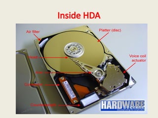
Inside HDA
• Thehard drive can have several discs. The one
on our picture had three discs. There is one
read/write read for each side of the disc –
which is also called platter. The heads are
stuck together in an arm. So, all the heads
move together.
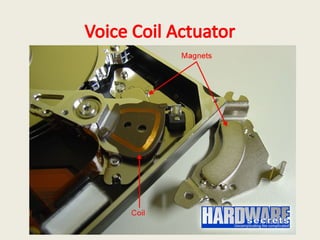
Actuator
• A motor(actually the correct term is
“actuator”) called voice coil moves the arm. It
is called “voice coil” because it uses the same
idea behind loudspeakers: a coil inside a
magnetic field provided by a magnet.
Depending on the current direction on the coil
the arm moves to one side or to the other
side. And depending on the intensity of the
current, the actuator will move more or less.