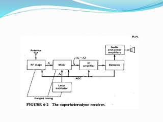
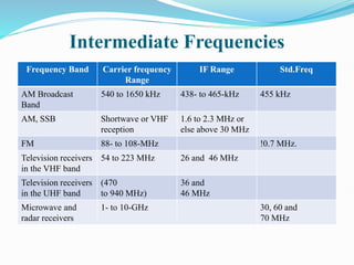
RADIO RECEIVER
Tuned radio-frequency (TRF) receiver
 Used as a fixed-frequency receiver in special
applications
 Simplicity
 High sensitivity
Tuned radio-frequency (TRF) receiver
 TRF receivers were simple to design and align at broadcast
frequencies (535 to 1640 kHz).
 Instability associated with high gain being achieved at one
frequency by a multistage amplifier.
 If such an amplifier has a gain of 40,000, all that is needed is
1/40,000 of the output of the last stage (positive feedback) to
find itself back at the input to the first stage, and oscillations
will occur, at the frequency at which the polarity of this
spurious feedback is positive.
 Such conditions are almost unavoidable at high frequencies and
is certainly not conducive to good receiver operation.
 TRF receiver suffered from a variation in bandwidth
over the tuning range.
 It was unable to achieve sufficient selectivity at high
frequencies, partly as a result of the enforced use of
single-tuned circuits.
 Several double-tuned amplifiers tune in unison were
too great
 Bandwidth of 10 kHz at a frequency of 535 kHz.
 Q of this circuit must be Q = f/BW= 535/10 = 53 .5.
 At 1640 kHz, Q=1640/10=164
 Q at 1640 kHz is unlikely to be in excess of 120, Q=XL/R
 Inductive reactance has to be increased which implies L
has to be increased.
 Hence bandwidth at 1640 kHz f/Q= 1640/120 =13.7 kHz
 The receiver will pick up adjacent stations as well as the
one to which it is tuned.
 tune to 36.5 MHz Q = 36,500/10 = 3650
Disadvantages of TRF Receiver
 Instability
 Insufficient adjacent-frequency rejection
 Bandwidth variation
Superheterodyne Receiver
 A constant frequency difference is maintained between the
local oscillator and the RF circuit;
 This is done through capacitance tuning, in which all the
capacitors are ganged together and operated in unison by
one control knob.
 The IF amplifier generally uses two or three transformers,
each consisting of a pair of mutually coupled tuned
circuits.
 With this large number of double-tuned circuits operating
at a constant, specially chosen frequency, the IF amplifier
provides most of the gain (and therefore sensitivity) and
bandwidth requirements of the receiver.
 Since the characteristics of the IF amplifier are
independent of the frequency to which the receiver is
tuned, the selectivity and sensitivity of the superhet are
usually fairly uniform throughout its tuning range and not
subject to the variations that affect the TRF receiver.
 The RF Circuits used mainly to select the wanted
frequency, to reject interference such as the image
frequency and (especially at high frequencies) to reduce
the noise figure of the receiver.
 The RF stage is normally a wideband RF amplifier tunable
from: approximately 540 kHz to 1650 kHz
 The local oscillator is a variable oscillator capable of
generating a signal from 0.995 MHz to 2.105 MHz.
 The incoming signal from the transmitter is selected and
amplified by the RF stage.
 It is then combined (mixed) with a predetermined local
oscillator signal in the mixer stage.
 During this stage, a class C nonlinear device processes the
signals, producing the sum, difference, and originals.
 The signal from the mixer is then supplied to the IF
(intermediate-frequency) amplifier.
 This amplifier is a very-narrow-bandwidth class A device
capable of selecting a frequency of 455 kHz ± 3 kHz and
rejecting all others.
 Detector stage: eliminates one of the sidebands still
present and separates the RF from the audio components
of the other sideband
1. Select an AM station, i.e., 640 kHz.
2. · Tune the RF amplifier to the lower end of the AM band.
3. Tune the RF amplifier. This also tunes the local oscillator
to a predetermined frequency of 1095 kHz.
4. Mix the 1095 kHz and 640 kHz. This produces the
following signals at the output of the mixer circuit; these
signals are then fed to the IF amplifier:
a. 1095-KHz local oscillator frequency
b. 640-kHz AM station carrier frequency
c. 455-kHz difference frequency
d. 1735-kHz sum frequency
 The process of tuning the local oscillator to a
predetermined frequency for each station throughout the
AM band is known as tracking.
 Direct conversion receiver: mixer output is audio
 Sensitivity. The sensitivity of a radio receiver is its ability to
amplify weak signals.
 It is often defined in terms of the voltage that must be applied
to the receiver input terminals to give a standard output power,
measured at the output terminals.
 Thus 30 percent modulation by a 400-Hz sine wave is used,
and the signal is applied to the receiver through a standard
coupling network known as a dummy antenna.
 The standard output is 50 milliwatts (50 rnW), and for all types
of receivers the loudspeaker is replaced by a load resistance of
equal value.
 Selectivity The selectivity of a receiver is its ability
to reject unwanted signals
 Frequency of the generator is varied to either side of the
frequency to which the receiver is tuned
 The output of the receiver naturally falls, since the input
frequency is now incorrect.
 The input voltage must be increased until the output is the
same as it was originally.
 The, ratio of the voltage required of resonance to the voltage
required when the generator is tuned to the receiver's frequency
is calculated at a number of points and then plotted in decibels
to give a curve
Image frequency and its rejection
 Image frequency is defined as the signal frequency plus
twice the intermediate frequency
i
s
i
i
s
i
o
si
i
o
s
i
s
o
f
f
f
f
f
f
f
f
f
f
f
f
f
f
2











 The rejection of an image frequency by a single-tuned
circuit, i.e., the ratio of the gain at the signal frequency
to the gain at the image frequency, (Image frequency
rejection ratio) is given by
 IFRR=Gain at signal frequency/Gain at Image frequency
 If fsi/fs
 large, as it is in the AM broadcast band, the use of an RF
stage is not essential for good image-frequency rejection,
but it does become necessary above about 3 MHz
 Image rejection depends on the front-end selectivity of the
receiver and must be achieved before the IF stage.
Adjacent channel selectivity
(Double spotting)
 picking up of the same shortwave station at two nearby
points on the receiver dial.
 It is caused by poor front-end selectivity, i.e.,
inadequate image-frequency rejection
Functions of RF amplifier
 1. Greater gain, i.e., better sensitivity
 2. Improved image-frequency rejection
 3. Improved signal-to-noise ratio
 4. Improved rejection of adjacent unwanted signals, i.e., better
selectivity
 5. Better coupling of the receiver to the antenna (important at
VHF and above)
 6. Prevention of spurious frequencies from entering the mixer
and heterodyning there to produce an interfering frequency
equal to the IF from the desired signal
 Prevention of reradiation of the local oscillator through the
antenna of the receiver (relatively rare)
 Signal frequency range from 540 to 1650 kHz
 Local oscillator frequency above signal frequency: 995 to
2105 kHz,
 Ratio of maximum to minimum frequencies : 2.2: 1
 Local oscillator below signal frequency: 85 to 1195 kHz,
ratio of maximum to minimum frequencies : 14: 1
 Normal tunable capacitor has a capacitance ratio of
approximately 10:1 giving a frequency ratio of 3.2: 1.
Hence the 2.2: I ratio required of the local oscillator
 operating above signal frequency is selected.
Choice of Intermediate Frequencies
 1. If the intermediate frequency is too high, poor
selectivity and poor adjacent channel rejection result
unless sharp cutoff (e.g., crystal or mechanical) filters are
used in the IF stages.
 2. A high value of intermediate frequency increases
tracking difficulties.
 3. As the intermediate frequency is lowered, image-
frequency rejection becomes poorer
Choice of Intermediate Frequencies
 A very low intermediate frequency can make the
selectivity too sharp, cutting off the sidebands.
 This problem arises because the Q must be low when the
IF is low, unless crystal or mechanical filters are used, and
therefore the gain per stage is low.
 A designer is more likely to raise the Q than to increase
the number of IF amplifiers.
Choice of Intermediate Frequencies
 5.If the IF is very low, the frequency stability of the local
oscillator must be made correspondingly higher because
any frequency drift is now a larger proportion of the low
IF than of a high IF.
 6. The intermediate frequency must not fall within the
tuning range of the receiver, or else instability will occur
and heterodyne whistles will be heard, making it
impossible to tune to the frequency band immediately
adjacent to the intermediate frequency.
Intermediate Frequencies
Frequency Band Carrier frequency
Range
IF Range Std.Freq
AM Broadcast
Band
540 to 1650 kHz 438- to 465-kHz 455 kHz
AM, SSB Shortwave or VHF
reception
1.6 to 2.3 MHz or
else above 30 MHz
FM 88- to 108-MHz !0.7 MHz.
Television receivers
in the VHF band
54 to 223 MHz 26 and 46 MHz
Television receivers
in the UHF band
(470
to 940 MHz)
36 and
46 MHz
Microwave and
radar receivers
1- to 10-GHz 30, 60 and
70 MHz
FM RECEIVERS
 1. Generally much higher operating frequencies in
FM
 2. Need for limiting and de-emphasis in FM
 3. Totally different methods of demodulation
 4. Different methods of obtaining AGC
 bandwidth of 200 kHz
REFERENCES
1.Electronic Communications, Dennis Roddy, John
Coolen, Pearson Education, Fourth Edition.
2. Electronic Communication Systems, George Kennedy,
Bernard Davis, TMH, Fourth edition.

Radio Receiver ppt presentation on .pptx

  • 1.
  • 2.
    Tuned radio-frequency (TRF)receiver  Used as a fixed-frequency receiver in special applications  Simplicity  High sensitivity
  • 3.
  • 4.
     TRF receiverswere simple to design and align at broadcast frequencies (535 to 1640 kHz).  Instability associated with high gain being achieved at one frequency by a multistage amplifier.  If such an amplifier has a gain of 40,000, all that is needed is 1/40,000 of the output of the last stage (positive feedback) to find itself back at the input to the first stage, and oscillations will occur, at the frequency at which the polarity of this spurious feedback is positive.  Such conditions are almost unavoidable at high frequencies and is certainly not conducive to good receiver operation.
  • 5.
     TRF receiversuffered from a variation in bandwidth over the tuning range.  It was unable to achieve sufficient selectivity at high frequencies, partly as a result of the enforced use of single-tuned circuits.  Several double-tuned amplifiers tune in unison were too great
  • 6.
     Bandwidth of10 kHz at a frequency of 535 kHz.  Q of this circuit must be Q = f/BW= 535/10 = 53 .5.  At 1640 kHz, Q=1640/10=164  Q at 1640 kHz is unlikely to be in excess of 120, Q=XL/R  Inductive reactance has to be increased which implies L has to be increased.  Hence bandwidth at 1640 kHz f/Q= 1640/120 =13.7 kHz  The receiver will pick up adjacent stations as well as the one to which it is tuned.  tune to 36.5 MHz Q = 36,500/10 = 3650
  • 7.
    Disadvantages of TRFReceiver  Instability  Insufficient adjacent-frequency rejection  Bandwidth variation
  • 8.
    Superheterodyne Receiver  Aconstant frequency difference is maintained between the local oscillator and the RF circuit;  This is done through capacitance tuning, in which all the capacitors are ganged together and operated in unison by one control knob.  The IF amplifier generally uses two or three transformers, each consisting of a pair of mutually coupled tuned circuits.
  • 10.
     With thislarge number of double-tuned circuits operating at a constant, specially chosen frequency, the IF amplifier provides most of the gain (and therefore sensitivity) and bandwidth requirements of the receiver.  Since the characteristics of the IF amplifier are independent of the frequency to which the receiver is tuned, the selectivity and sensitivity of the superhet are usually fairly uniform throughout its tuning range and not subject to the variations that affect the TRF receiver.
  • 11.
     The RFCircuits used mainly to select the wanted frequency, to reject interference such as the image frequency and (especially at high frequencies) to reduce the noise figure of the receiver.  The RF stage is normally a wideband RF amplifier tunable from: approximately 540 kHz to 1650 kHz  The local oscillator is a variable oscillator capable of generating a signal from 0.995 MHz to 2.105 MHz.
  • 12.
     The incomingsignal from the transmitter is selected and amplified by the RF stage.  It is then combined (mixed) with a predetermined local oscillator signal in the mixer stage.  During this stage, a class C nonlinear device processes the signals, producing the sum, difference, and originals.
  • 13.
     The signalfrom the mixer is then supplied to the IF (intermediate-frequency) amplifier.  This amplifier is a very-narrow-bandwidth class A device capable of selecting a frequency of 455 kHz ± 3 kHz and rejecting all others.  Detector stage: eliminates one of the sidebands still present and separates the RF from the audio components of the other sideband
  • 14.
    1. Select anAM station, i.e., 640 kHz. 2. · Tune the RF amplifier to the lower end of the AM band. 3. Tune the RF amplifier. This also tunes the local oscillator to a predetermined frequency of 1095 kHz. 4. Mix the 1095 kHz and 640 kHz. This produces the following signals at the output of the mixer circuit; these signals are then fed to the IF amplifier: a. 1095-KHz local oscillator frequency b. 640-kHz AM station carrier frequency c. 455-kHz difference frequency d. 1735-kHz sum frequency
  • 15.
     The processof tuning the local oscillator to a predetermined frequency for each station throughout the AM band is known as tracking.  Direct conversion receiver: mixer output is audio
  • 16.
     Sensitivity. Thesensitivity of a radio receiver is its ability to amplify weak signals.  It is often defined in terms of the voltage that must be applied to the receiver input terminals to give a standard output power, measured at the output terminals.  Thus 30 percent modulation by a 400-Hz sine wave is used, and the signal is applied to the receiver through a standard coupling network known as a dummy antenna.  The standard output is 50 milliwatts (50 rnW), and for all types of receivers the loudspeaker is replaced by a load resistance of equal value.
  • 18.
     Selectivity Theselectivity of a receiver is its ability to reject unwanted signals
  • 19.
     Frequency ofthe generator is varied to either side of the frequency to which the receiver is tuned  The output of the receiver naturally falls, since the input frequency is now incorrect.  The input voltage must be increased until the output is the same as it was originally.  The, ratio of the voltage required of resonance to the voltage required when the generator is tuned to the receiver's frequency is calculated at a number of points and then plotted in decibels to give a curve
  • 20.
    Image frequency andits rejection  Image frequency is defined as the signal frequency plus twice the intermediate frequency i s i i s i o si i o s i s o f f f f f f f f f f f f f f 2           
  • 21.
     The rejectionof an image frequency by a single-tuned circuit, i.e., the ratio of the gain at the signal frequency to the gain at the image frequency, (Image frequency rejection ratio) is given by  IFRR=Gain at signal frequency/Gain at Image frequency
  • 22.
     If fsi/fs large, as it is in the AM broadcast band, the use of an RF stage is not essential for good image-frequency rejection, but it does become necessary above about 3 MHz  Image rejection depends on the front-end selectivity of the receiver and must be achieved before the IF stage.
  • 26.
    Adjacent channel selectivity (Doublespotting)  picking up of the same shortwave station at two nearby points on the receiver dial.  It is caused by poor front-end selectivity, i.e., inadequate image-frequency rejection
  • 27.
    Functions of RFamplifier  1. Greater gain, i.e., better sensitivity  2. Improved image-frequency rejection  3. Improved signal-to-noise ratio  4. Improved rejection of adjacent unwanted signals, i.e., better selectivity  5. Better coupling of the receiver to the antenna (important at VHF and above)  6. Prevention of spurious frequencies from entering the mixer and heterodyning there to produce an interfering frequency equal to the IF from the desired signal  Prevention of reradiation of the local oscillator through the antenna of the receiver (relatively rare)
  • 29.
     Signal frequencyrange from 540 to 1650 kHz  Local oscillator frequency above signal frequency: 995 to 2105 kHz,  Ratio of maximum to minimum frequencies : 2.2: 1  Local oscillator below signal frequency: 85 to 1195 kHz, ratio of maximum to minimum frequencies : 14: 1  Normal tunable capacitor has a capacitance ratio of approximately 10:1 giving a frequency ratio of 3.2: 1. Hence the 2.2: I ratio required of the local oscillator  operating above signal frequency is selected.
  • 30.
    Choice of IntermediateFrequencies  1. If the intermediate frequency is too high, poor selectivity and poor adjacent channel rejection result unless sharp cutoff (e.g., crystal or mechanical) filters are used in the IF stages.  2. A high value of intermediate frequency increases tracking difficulties.  3. As the intermediate frequency is lowered, image- frequency rejection becomes poorer
  • 31.
    Choice of IntermediateFrequencies  A very low intermediate frequency can make the selectivity too sharp, cutting off the sidebands.  This problem arises because the Q must be low when the IF is low, unless crystal or mechanical filters are used, and therefore the gain per stage is low.  A designer is more likely to raise the Q than to increase the number of IF amplifiers.
  • 32.
    Choice of IntermediateFrequencies  5.If the IF is very low, the frequency stability of the local oscillator must be made correspondingly higher because any frequency drift is now a larger proportion of the low IF than of a high IF.  6. The intermediate frequency must not fall within the tuning range of the receiver, or else instability will occur and heterodyne whistles will be heard, making it impossible to tune to the frequency band immediately adjacent to the intermediate frequency.
  • 33.
    Intermediate Frequencies Frequency BandCarrier frequency Range IF Range Std.Freq AM Broadcast Band 540 to 1650 kHz 438- to 465-kHz 455 kHz AM, SSB Shortwave or VHF reception 1.6 to 2.3 MHz or else above 30 MHz FM 88- to 108-MHz !0.7 MHz. Television receivers in the VHF band 54 to 223 MHz 26 and 46 MHz Television receivers in the UHF band (470 to 940 MHz) 36 and 46 MHz Microwave and radar receivers 1- to 10-GHz 30, 60 and 70 MHz
  • 35.
    FM RECEIVERS  1.Generally much higher operating frequencies in FM  2. Need for limiting and de-emphasis in FM  3. Totally different methods of demodulation  4. Different methods of obtaining AGC  bandwidth of 200 kHz
  • 37.
    REFERENCES 1.Electronic Communications, DennisRoddy, John Coolen, Pearson Education, Fourth Edition. 2. Electronic Communication Systems, George Kennedy, Bernard Davis, TMH, Fourth edition.