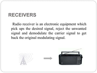
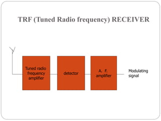
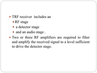
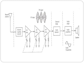
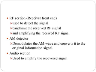
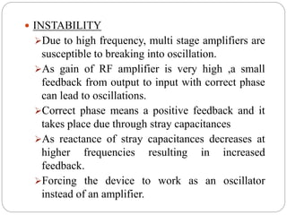
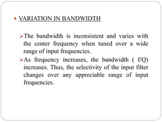
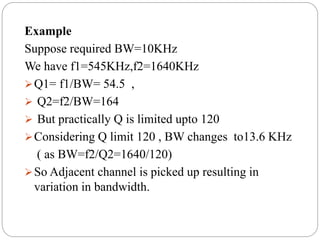
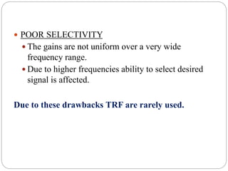
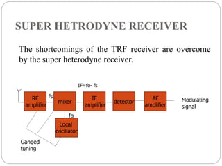
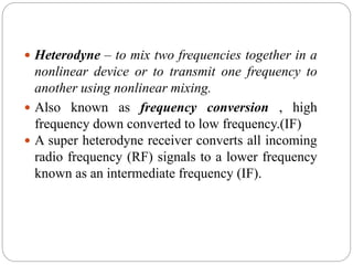
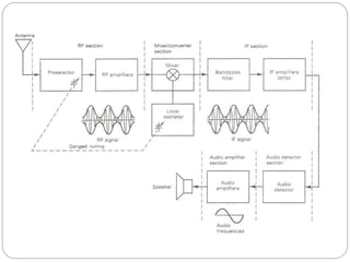
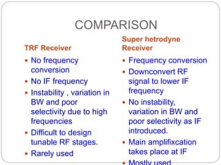
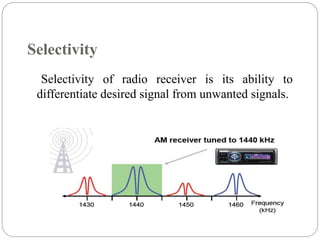
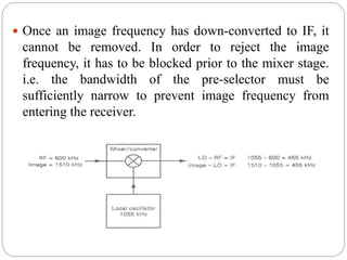
Presented By :-
Er. Srishtee Chaudhary
Lecturer E.C.E
GPCG,Patiala
RECEIVERS
RECEIVERS
Radio receiver is an electronic equipment which
pick ups the desired signal, reject the unwanted
signal and demodulate the carrier signal to get
back the original modulating signal.
Function of Radio Receivers
 Intercept the incoming modulated signal
 Select desired signal and reject unwanted signals
 Amplify selected R.F signal
 Detect modulated signal to get back original
modulating signal
 Amplify modulating frequency signal
Design of Receiver
 The radio receiver has to be cost effective
 Requirements:
 Has to work according to application as for AM
or FM signals
 Tune to and amplify desired radio station
 Filter out all other stations
 Demodulator has to work with all radio stations
regardless of carrier frequency
Classification of Radio Receivers
Depending upon application
 AM Receivers - receive broadcast of speech or
music from AM transmitters which operate on long
wave, medium wave or short wave bands.
 FM Receivers – receive broadcast programs from
FM transmitters which operate in VHF or UHF
bands.
 Communication Receivers - used for reception of
telegraph and short wave telephone signals.
 Television Receivers - used to receive television
broadcast in VHF or UHF bands.
 Radar Receivers – used to receive radio detection
and ranging signals.
Depending upon fundamental aspects
 Tuned Radio Frequency (TRF)Receivers
 Super-heterodyne Receivers
RECEIVERS
Tuned Radio Frequency (TRF) Receiver:
 Composed of RF amplifiers and detectors.
 No frequency conversion
 It is not often used.
 Difficult to design tunable RF stages.
 Difficult to obtain high gain RF amplifiers
Super-hetrodyne Receiver
 Downconvert RF signal to lower IF frequency
 Main amplifixcation takes place at IF
Communication Receiver
 Downconvert RF signal to two IF frequency
TRF (Tuned Radio frequency) RECEIVER
Tuned radio
frequency
amplifier
detector
A. F.
amplifier
Modulating
signal
 TRF receiver includes an
 RF stage
 a detector stage
 and an audio stage .
 Two or three RF amplifiers are required to filter
and amplify the received signal to a level sufficient
to drive the detector stage.
 RF section (Receiver front end)
used to detect the signal
bandlimit the received RF signal
and amplifying the received RF signal.
 AM detector
Demodulates the AM wave and converts it to the
original information signal.
 Audio section
Used to amplify the recovered signal
Advantages of TRF
 TRF receivers are simple to design and allow the
broadcast frequency 535 KHz to 1640 KHz.
 High senstivity.
Disadvantages of TRF
 At the higher frequency, it produces difficulty in
design.
 It has poor audio quality.
 Drawbacks
 Instability
 Variation in BW
 Poor Selectivity
 INSTABILITY
Due to high frequency, multi stage amplifiers are
susceptible to breaking into oscillation.
As gain of RF amplifier is very high ,a small
feedback from output to input with correct phase
can lead to oscillations.
Correct phase means a positive feedback and it
takes place due through stray capacitances
As reactance of stray capacitances decreases at
higher frequencies resulting in increased
feedback.
Forcing the device to work as an oscillator
instead of an amplifier.
 VARIATION IN BANDWIDTH
The bandwidth is inconsistent and varies with
the center frequency when tuned over a wide
range of input frequencies.
As frequency increases, the bandwidth ( f/Q)
increases. Thus, the selectivity of the input filter
changes over any appreciable range of input
frequencies.
Example
Suppose required BW=10KHz
We have f1=545KHz,f2=1640KHz
Q1= f1/BW= 54.5 ,
 Q2=f2/BW=164
 But practically Q is limited upto 120
Considering Q limit 120 , BW changes to13.6 KHz
( as BW=f2/Q2=1640/120)
So Adjacent channel is picked up resulting in
variation in bandwidth.
 POOR SELECTIVITY
 The gains are not uniform over a very wide
frequency range.
 Due to higher frequencies ability to select desired
signal is affected.
Due to these drawbacks TRF are rarely used.
SUPER HETRODYNE RECEIVER
RF
amplifier
Local
oscillator
mixer
IF
amplifier
detector
AF
amplifier
Modulating
signal
Ganged
tuning
fs
fo
IF=fo- fs
The shortcomings of the TRF receiver are overcome
by the super heterodyne receiver.
 Heterodyne – to mix two frequencies together in a
nonlinear device or to transmit one frequency to
another using nonlinear mixing.
 Also known as frequency conversion , high
frequency down converted to low frequency.(IF)
 A super heterodyne receiver converts all incoming
radio frequency (RF) signals to a lower frequency
known as an intermediate frequency (IF).
DRAWBACKS OVERCOMED
 Stability – as high frequency is down converted to
IF the reactance of stray capacitances will not
decrease as it was at higher frequencies resulting in
increased feedback.
 No variation in BW- as IF range is 438 to 465 KHz
(in case of AM receivers) mostly 455KHz
,appropriate for Q limit (120).
 Better selectivity- as no adjacent channels are
picked due to variation in BW.
 RF section
 Consists of a pre-selector and an amplifier
 Pre-selector is a broad-tuned bandpass filter with an
adjustable center frequency used to reject unwanted
radio frequency and to reduce the noise bandwidth.
 RF amplifier determines the sensitivity of the
receiver and a predominant factor in determining the
noise figure for the receiver.
 Mixer/converter section
 Consists of a radio-frequency oscillator and a mixer.
 Choice of oscillator depends on the stability and
accuracy desired.
 Mixer is a nonlinear device to convert radio
frequency to intermediate frequencies (i.e.
heterodyning process).
 The shape of the envelope, the bandwidth and the
original information contained in the envelope
remains unchanged although the carrier and
sideband frequencies are translated from RF to IF.
 IF section
 Consists of a series of IF amplifiers and bandpass
filters to achieve most of the receiver gain and
selectivity.
 The IF is always lower than the RF because it is
easier and less expensive to construct high-gain,
stable amplifiers for low frequency signals.
 IF amplifiers are also less likely to oscillate than
their RF counterparts.
 Detector section
 To convert the IF signals back to the original
source information (demodulation).
 Can be as simple as a single diode or as complex
as a PLL or balanced demodulator.
 Audio amplifier section
 Comprises several cascaded audio amplifiers and
one or more speakers
 AGC ( Automatic Gain Control )
 Adjust the IF amplifier gain according to signal
level(to the average amplitude signal almost
constant).
 AGC is a system by means of which the overall
gain of radio receiver is varied automatically with
the variations in the strength of received signals,
to maintain the output constant.
 AGC circuit is used to adjust and stabilize the
frequency of local oscillator.
 Types of AGC –
 No AGC
Simple AGC
Delayed AGC
 FREQUENCY CONVERSION in the mixer stage is
identical to the frequency conversion in the
modulator except that in the receiver, the frequencies
are down-converted rather that up-converted.
 In the mixer, RF signals are combined with the
local oscillator frequency
 The local oscillator is designed such that its
frequency of oscillation is always above or below
the desired RF carrier by an amount equal to the IF
center frequency.
 Therefore the difference of RF and oscillator
frequency is always equal to the IF frequency
 The adjustment for the center frequency of the pre-
selector and the local oscillator frequency are gang-
tune (the two adjustments are tied together so that
single adjustment will change the center frequency of
the pre-selector and at the same time change the local
oscillator)
 when local oscillator frequency is tuned above the
RF – high side injection
when local oscillator frequency is tuned below the
RF – low side injection
 Mathematically expressed :
High side injection
Low side injection IF
RF
lo f
f
f 

IF
RF
lo f
f
f 

COMPARISON
TRF Receiver
Super hetrodyne
Receiver
 No frequency
conversion
 No IF frequency
 Instability , variation in
BW and poor
selectivity due to high
frequencies
 Difficult to design
tunable RF stages.
 Rarely used
 Frequency conversion
 Downconvert RF
signal to lower IF
frequency
 No instability,
variation in BW and
poor selectivity as IF
introduced.
 Main amplifixcation
takes place at IF
CHARACTERISTICS OF RADIO RECEIVERS
 Sensitivity
 Selectivity
 Fidelity
Sensitivity
 Ability to amplify weak signals.
 Minimum RF signal level that can be detected at
the input to the receiver and still produce a usable
demodulated information signal.
 Broadcast receivers/ radio receivers should have
reasonably high sensitivity so that it may have good
response to the desired signal
 But should not have excessively high sensitivity
otherwise it will pick up all undesired noise signals.
 It is function of receiver gain and measures in
decibels.
 Sensitivity of a receiver is expressed in microvolts
of the received signal.
 Typical sensitivity for commercial broadcast-band
AM receiver is 50 μV.
 Sensitivity of the receiver depends on :
1.Noise power present at the input to the receiver
2.Receiver noise figure
3.Bandwidth improvement factor of the receiver
The best way to improve the sensitivity is to
reduce the noise level.
Selectivity
Selectivity of radio receiver is its ability to
differentiate desired signal from unwanted signals.
 Selectivity is obtained by using tuned circuits,
which are tuned to desired frequency. The quality
factor of these LC circuits determines the
selectivity. It is given by,
Q=XL/R
 For better selectivity ‘Q’ should be high.
Fidelity
 Fidelity is defined as – a measure of the ability of a
communication system to produce an exact replica
of the original source information at the output of
the receiver.
 Any variations in the demodulated signal that are
not in the original information signal is considered
as distortion.
 Radio receiver should have high fidelity or
accuracy.
 Example- In an A.M. broadcast the maximum audio
frequency is 5 KHz hence receiver with good
fidelity must produce entire frequency up to 5KHz.
IMAGE FREQUENCY
 In radio reception using heterodyning in the tuning
process, an undesired input frequency that is
capable of producing the same intermediate
frequency (IF) that the desired input frequency
produces.
 Image frequency – any frequency other than the
selected radio frequency carrier that will produce
a cross-product frequency that is equal to the
intermediate frequency if allowed to enter a
receiver and mix with the local oscillator.
 It is given by signal frequency plus twice the
intermediate frequency
fsi = fs + 2fi
 It is equivalent to a second radio frequency that
will produce an IF that will interfere with the IF
from the desired radio frequency.
 if the selected RF carrier and its image frequency
enter a receiver at a same time, they both mix
with the local oscillator frequency and produce
different frequencies that are equal to the IF.
 Consequently, two different stations are received
and demodulated simultaneously
 The higher the IF, the farther away the image
frequency is from the desired radio frequency.
Therefore, for better image frequency rejection, a
high IF is preferred.
 However, the higher the IF, it is more difficult to
build a stable amplifier with high gain. i.e. there is
a trade-off when selecting the IF for a radio
receiver (image frequency rejection vs IF gain and
stability)
MATHEMATICAL ANALYSIS
 Basic principle with two frequencies component f1
and f2,we have harmonics f1,f2,f1+f2,f1-f2
 In case of radio receivers, two frequency
components are fo and fs
 So harmonic we have fo,fs,fo+fs,fo-fs
 Let Undesired frequency fsi(=fo+fif) able to reach
at the mixer
 So now two frequency components will be fo (local
oscillator) and fsi (undesired freq)
 And harmonics will be fo,fsi,fo+fsi,fo-fsi
 Substituting value of fsi we have
 fo,fo+fs,2fo+fif,fif
 It was observed that difference component is a
mirror image of IF
 Consequently, 2 different stations are received
and demodulated simultaneously
 Once an image frequency has down-converted to IF, it
cannot be removed. In order to reject the image
frequency, it has to be blocked prior to the mixer stage.
i.e. the bandwidth of the pre-selector must be
sufficiently narrow to prevent image frequency from
entering the receiver.
CHOICE OF IF
 Very high IF will result in poor selectivity and poor
adjacent channel rejection
 A high value of IF will result in tracking
difficulties
 At low values of IF image frequency rejection is
poor. Also the selectivity will be too sharp that cut
off the sidebands
THANKS

RECEIVERS.ppt

  • 1.
    Presented By :- Er.Srishtee Chaudhary Lecturer E.C.E GPCG,Patiala RECEIVERS
  • 2.
    RECEIVERS Radio receiver isan electronic equipment which pick ups the desired signal, reject the unwanted signal and demodulate the carrier signal to get back the original modulating signal.
  • 3.
    Function of RadioReceivers  Intercept the incoming modulated signal  Select desired signal and reject unwanted signals  Amplify selected R.F signal  Detect modulated signal to get back original modulating signal  Amplify modulating frequency signal
  • 4.
    Design of Receiver The radio receiver has to be cost effective  Requirements:  Has to work according to application as for AM or FM signals  Tune to and amplify desired radio station  Filter out all other stations  Demodulator has to work with all radio stations regardless of carrier frequency
  • 5.
    Classification of RadioReceivers Depending upon application  AM Receivers - receive broadcast of speech or music from AM transmitters which operate on long wave, medium wave or short wave bands.  FM Receivers – receive broadcast programs from FM transmitters which operate in VHF or UHF bands.
  • 6.
     Communication Receivers- used for reception of telegraph and short wave telephone signals.  Television Receivers - used to receive television broadcast in VHF or UHF bands.  Radar Receivers – used to receive radio detection and ranging signals.
  • 7.
    Depending upon fundamentalaspects  Tuned Radio Frequency (TRF)Receivers  Super-heterodyne Receivers
  • 8.
    RECEIVERS Tuned Radio Frequency(TRF) Receiver:  Composed of RF amplifiers and detectors.  No frequency conversion  It is not often used.  Difficult to design tunable RF stages.  Difficult to obtain high gain RF amplifiers
  • 9.
    Super-hetrodyne Receiver  DownconvertRF signal to lower IF frequency  Main amplifixcation takes place at IF Communication Receiver  Downconvert RF signal to two IF frequency
  • 10.
    TRF (Tuned Radiofrequency) RECEIVER Tuned radio frequency amplifier detector A. F. amplifier Modulating signal
  • 11.
     TRF receiverincludes an  RF stage  a detector stage  and an audio stage .  Two or three RF amplifiers are required to filter and amplify the received signal to a level sufficient to drive the detector stage.
  • 13.
     RF section(Receiver front end) used to detect the signal bandlimit the received RF signal and amplifying the received RF signal.  AM detector Demodulates the AM wave and converts it to the original information signal.  Audio section Used to amplify the recovered signal
  • 14.
    Advantages of TRF TRF receivers are simple to design and allow the broadcast frequency 535 KHz to 1640 KHz.  High senstivity.
  • 15.
    Disadvantages of TRF At the higher frequency, it produces difficulty in design.  It has poor audio quality.  Drawbacks  Instability  Variation in BW  Poor Selectivity
  • 16.
     INSTABILITY Due tohigh frequency, multi stage amplifiers are susceptible to breaking into oscillation. As gain of RF amplifier is very high ,a small feedback from output to input with correct phase can lead to oscillations. Correct phase means a positive feedback and it takes place due through stray capacitances As reactance of stray capacitances decreases at higher frequencies resulting in increased feedback. Forcing the device to work as an oscillator instead of an amplifier.
  • 17.
     VARIATION INBANDWIDTH The bandwidth is inconsistent and varies with the center frequency when tuned over a wide range of input frequencies. As frequency increases, the bandwidth ( f/Q) increases. Thus, the selectivity of the input filter changes over any appreciable range of input frequencies.
  • 18.
    Example Suppose required BW=10KHz Wehave f1=545KHz,f2=1640KHz Q1= f1/BW= 54.5 ,  Q2=f2/BW=164  But practically Q is limited upto 120 Considering Q limit 120 , BW changes to13.6 KHz ( as BW=f2/Q2=1640/120) So Adjacent channel is picked up resulting in variation in bandwidth.
  • 19.
     POOR SELECTIVITY The gains are not uniform over a very wide frequency range.  Due to higher frequencies ability to select desired signal is affected. Due to these drawbacks TRF are rarely used.
  • 20.
  • 21.
     Heterodyne –to mix two frequencies together in a nonlinear device or to transmit one frequency to another using nonlinear mixing.  Also known as frequency conversion , high frequency down converted to low frequency.(IF)  A super heterodyne receiver converts all incoming radio frequency (RF) signals to a lower frequency known as an intermediate frequency (IF).
  • 22.
    DRAWBACKS OVERCOMED  Stability– as high frequency is down converted to IF the reactance of stray capacitances will not decrease as it was at higher frequencies resulting in increased feedback.  No variation in BW- as IF range is 438 to 465 KHz (in case of AM receivers) mostly 455KHz ,appropriate for Q limit (120).  Better selectivity- as no adjacent channels are picked due to variation in BW.
  • 24.
     RF section Consists of a pre-selector and an amplifier  Pre-selector is a broad-tuned bandpass filter with an adjustable center frequency used to reject unwanted radio frequency and to reduce the noise bandwidth.  RF amplifier determines the sensitivity of the receiver and a predominant factor in determining the noise figure for the receiver.
  • 25.
     Mixer/converter section Consists of a radio-frequency oscillator and a mixer.  Choice of oscillator depends on the stability and accuracy desired.  Mixer is a nonlinear device to convert radio frequency to intermediate frequencies (i.e. heterodyning process).  The shape of the envelope, the bandwidth and the original information contained in the envelope remains unchanged although the carrier and sideband frequencies are translated from RF to IF.
  • 26.
     IF section Consists of a series of IF amplifiers and bandpass filters to achieve most of the receiver gain and selectivity.  The IF is always lower than the RF because it is easier and less expensive to construct high-gain, stable amplifiers for low frequency signals.  IF amplifiers are also less likely to oscillate than their RF counterparts.
  • 27.
     Detector section To convert the IF signals back to the original source information (demodulation).  Can be as simple as a single diode or as complex as a PLL or balanced demodulator.  Audio amplifier section  Comprises several cascaded audio amplifiers and one or more speakers
  • 28.
     AGC (Automatic Gain Control )  Adjust the IF amplifier gain according to signal level(to the average amplitude signal almost constant).  AGC is a system by means of which the overall gain of radio receiver is varied automatically with the variations in the strength of received signals, to maintain the output constant.
  • 29.
     AGC circuitis used to adjust and stabilize the frequency of local oscillator.  Types of AGC –  No AGC Simple AGC Delayed AGC
  • 30.
     FREQUENCY CONVERSIONin the mixer stage is identical to the frequency conversion in the modulator except that in the receiver, the frequencies are down-converted rather that up-converted.  In the mixer, RF signals are combined with the local oscillator frequency  The local oscillator is designed such that its frequency of oscillation is always above or below the desired RF carrier by an amount equal to the IF center frequency.  Therefore the difference of RF and oscillator frequency is always equal to the IF frequency
  • 31.
     The adjustmentfor the center frequency of the pre- selector and the local oscillator frequency are gang- tune (the two adjustments are tied together so that single adjustment will change the center frequency of the pre-selector and at the same time change the local oscillator)  when local oscillator frequency is tuned above the RF – high side injection when local oscillator frequency is tuned below the RF – low side injection  Mathematically expressed : High side injection Low side injection IF RF lo f f f   IF RF lo f f f  
  • 33.
    COMPARISON TRF Receiver Super hetrodyne Receiver No frequency conversion  No IF frequency  Instability , variation in BW and poor selectivity due to high frequencies  Difficult to design tunable RF stages.  Rarely used  Frequency conversion  Downconvert RF signal to lower IF frequency  No instability, variation in BW and poor selectivity as IF introduced.  Main amplifixcation takes place at IF
  • 34.
    CHARACTERISTICS OF RADIORECEIVERS  Sensitivity  Selectivity  Fidelity
  • 35.
    Sensitivity  Ability toamplify weak signals.  Minimum RF signal level that can be detected at the input to the receiver and still produce a usable demodulated information signal.  Broadcast receivers/ radio receivers should have reasonably high sensitivity so that it may have good response to the desired signal  But should not have excessively high sensitivity otherwise it will pick up all undesired noise signals.  It is function of receiver gain and measures in decibels.
  • 36.
     Sensitivity ofa receiver is expressed in microvolts of the received signal.  Typical sensitivity for commercial broadcast-band AM receiver is 50 μV.  Sensitivity of the receiver depends on : 1.Noise power present at the input to the receiver 2.Receiver noise figure 3.Bandwidth improvement factor of the receiver The best way to improve the sensitivity is to reduce the noise level.
  • 37.
    Selectivity Selectivity of radioreceiver is its ability to differentiate desired signal from unwanted signals.
  • 38.
     Selectivity isobtained by using tuned circuits, which are tuned to desired frequency. The quality factor of these LC circuits determines the selectivity. It is given by, Q=XL/R  For better selectivity ‘Q’ should be high.
  • 39.
    Fidelity  Fidelity isdefined as – a measure of the ability of a communication system to produce an exact replica of the original source information at the output of the receiver.  Any variations in the demodulated signal that are not in the original information signal is considered as distortion.  Radio receiver should have high fidelity or accuracy.  Example- In an A.M. broadcast the maximum audio frequency is 5 KHz hence receiver with good fidelity must produce entire frequency up to 5KHz.
  • 40.
    IMAGE FREQUENCY  Inradio reception using heterodyning in the tuning process, an undesired input frequency that is capable of producing the same intermediate frequency (IF) that the desired input frequency produces.  Image frequency – any frequency other than the selected radio frequency carrier that will produce a cross-product frequency that is equal to the intermediate frequency if allowed to enter a receiver and mix with the local oscillator.  It is given by signal frequency plus twice the intermediate frequency fsi = fs + 2fi
  • 41.
     It isequivalent to a second radio frequency that will produce an IF that will interfere with the IF from the desired radio frequency.  if the selected RF carrier and its image frequency enter a receiver at a same time, they both mix with the local oscillator frequency and produce different frequencies that are equal to the IF.  Consequently, two different stations are received and demodulated simultaneously
  • 42.
     The higherthe IF, the farther away the image frequency is from the desired radio frequency. Therefore, for better image frequency rejection, a high IF is preferred.  However, the higher the IF, it is more difficult to build a stable amplifier with high gain. i.e. there is a trade-off when selecting the IF for a radio receiver (image frequency rejection vs IF gain and stability)
  • 43.
    MATHEMATICAL ANALYSIS  Basicprinciple with two frequencies component f1 and f2,we have harmonics f1,f2,f1+f2,f1-f2  In case of radio receivers, two frequency components are fo and fs  So harmonic we have fo,fs,fo+fs,fo-fs  Let Undesired frequency fsi(=fo+fif) able to reach at the mixer  So now two frequency components will be fo (local oscillator) and fsi (undesired freq)  And harmonics will be fo,fsi,fo+fsi,fo-fsi
  • 44.
     And harmonicswill be fo,fsi,fo+fsi,fo-fsi  Substituting value of fsi we have  fo,fo+fs,2fo+fif,fif  It was observed that difference component is a mirror image of IF  Consequently, 2 different stations are received and demodulated simultaneously
  • 45.
     Once animage frequency has down-converted to IF, it cannot be removed. In order to reject the image frequency, it has to be blocked prior to the mixer stage. i.e. the bandwidth of the pre-selector must be sufficiently narrow to prevent image frequency from entering the receiver.
  • 46.
    CHOICE OF IF Very high IF will result in poor selectivity and poor adjacent channel rejection  A high value of IF will result in tracking difficulties  At low values of IF image frequency rejection is poor. Also the selectivity will be too sharp that cut off the sidebands
  • 47.