Downloaded 117 times
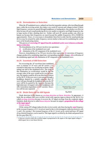
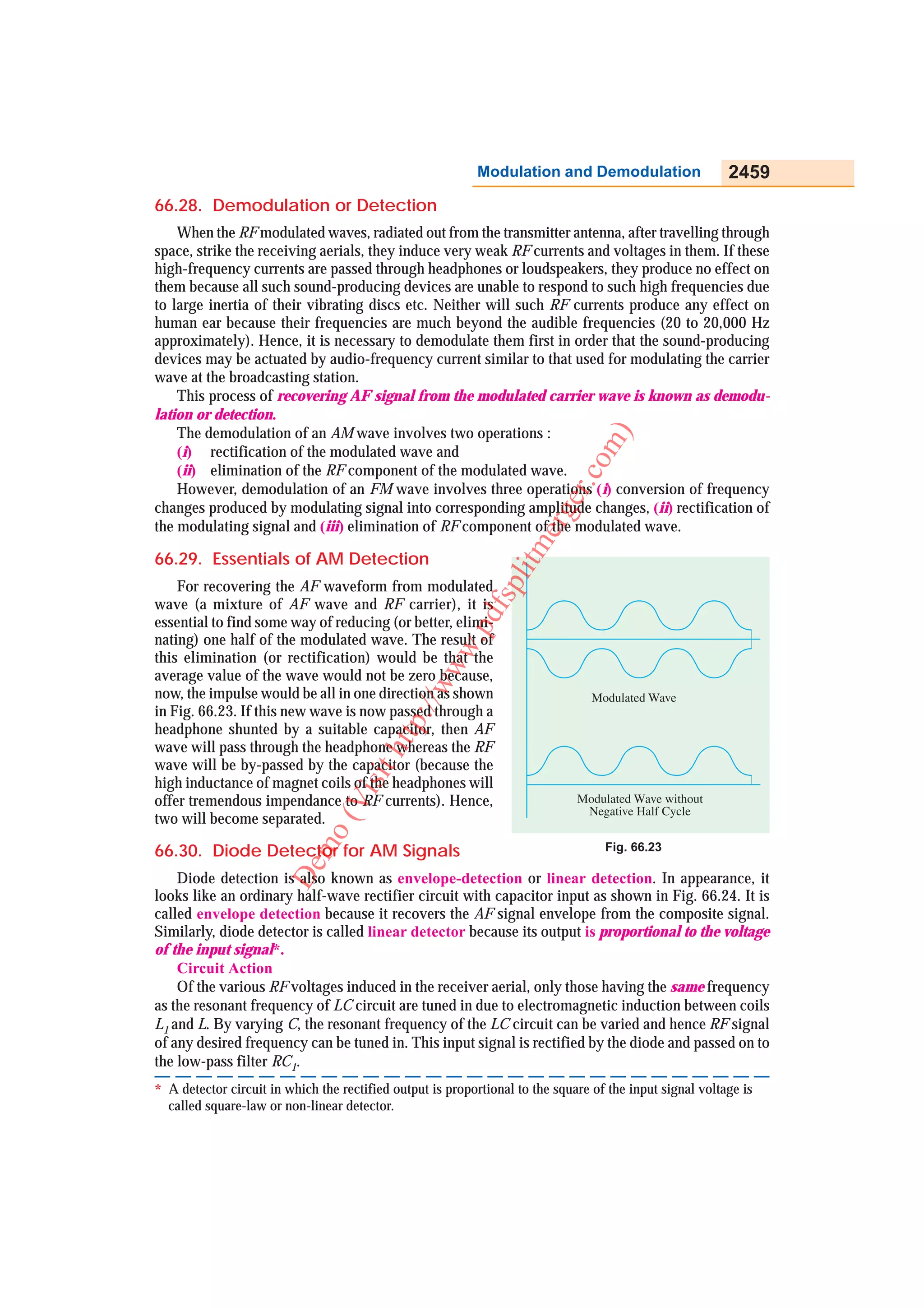
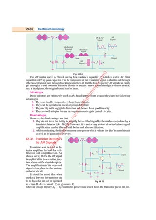
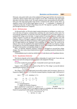

This document discusses demodulation, or detection, which is the process of recovering the audio frequency (AF) signal from a modulated radio frequency (RF) carrier wave. It describes the basic operations involved in demodulating an amplitude modulated (AM) wave and a frequency modulated (FM) wave. Specifically for AM detection, it explains the essential process of rectification using a diode detector circuit to recover the AF signal envelope. For FM detection, it discusses converting frequency variations in the FM signal into voltage changes using a quadrature detector circuit.


