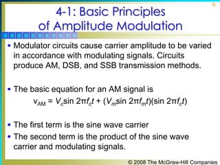
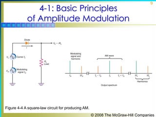
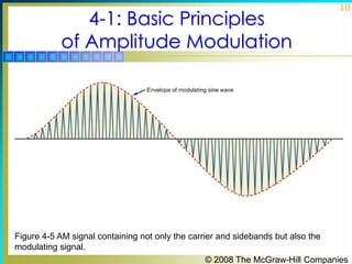
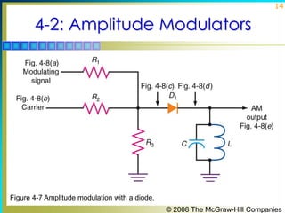
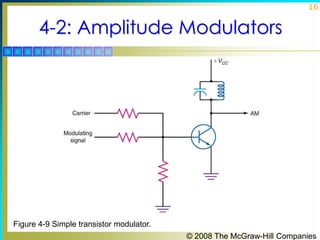
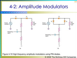
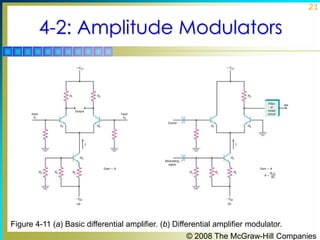
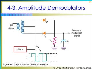
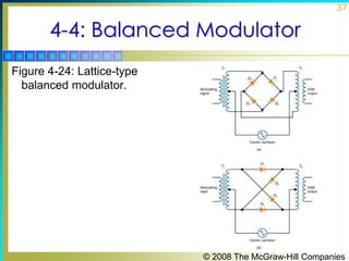
1

Principles of Electronic
Communication Systems
Third Edition
Louis E. Frenzel, Jr.

© 2008 The McGraw-Hill Companies
2

Chapter 4

Amplitude Modulator
and Demodulator Circuits
3

Topics Covered in Chapter 4
 4-1: Basic Principles of Amplitude Modulation
 4-2: Amplitude Modulators
 4-3: Amplitude Demodulators
 4-4: Balanced Modulators
 4-5: SSB Circuits

© 2008 The McGraw-Hill Companies
4-1: Basic Principles
of Amplitude Modulation

4

 Modulator circuits cause carrier amplitude to be varied

in accordance with modulating signals. Circuits
produce AM, DSB, and SSB transmission methods.
 The basic equation for an AM signal is

νAM = Vcsin 2πfct + (Vmsin 2πfmt)(sin 2πfct)
 The first term is the sine wave carrier
 The second term is the product of the sine wave

carrier and modulating signals.
© 2008 The McGraw-Hill Companies
4-1: Basic Principles
of Amplitude Modulation

5

AM in the Time Domain
 Amplitude modulation voltage is produced by a circuit

that can multiply the carrier by the modulating signal
and then add the carrier.
 If a circuit’s gain is a function of 1+ m sin 2πfmt, the

expression for the AM signal is
νAM = A(νc)
Where A is the gain or attenuation factor.

© 2008 The McGraw-Hill Companies
4-1: Basic Principles
of Amplitude Modulation

6

Figure 4-1 Block diagram of a circuit to produce AM.
© 2008 The McGraw-Hill Companies
4-1: Basic Principles
of Amplitude Modulation

7

AM in the Frequency Domain
 The product of the carrier and modulating signal can be

generated by applying both signals to a nonlinear
component such as a diode.
 A square-law function is one that varies in proportion
to the square of the input signals. A diode gives a good
approximation of a square-law response. Bipolar and
field-effect transistors (FETs) can also be biased to give
a square-law response.

© 2008 The McGraw-Hill Companies
4-1: Basic Principles
of Amplitude Modulation

8

AM in the Frequency Domain
 Diodes and transistors whose function is not a pure

square-law function produce third-, fourth-, and higherorder harmonics, which are sometimes referred to as
intermodulation products.
 Intermodulation products are easy to filter out.
 Tuned circuits filter out the modulating signal and carrier
harmonics, leaving only carrier and sidebands.

© 2008 The McGraw-Hill Companies
4-1: Basic Principles
of Amplitude Modulation

9

Figure 4-4 A square-law circuit for producing AM.
© 2008 The McGraw-Hill Companies
4-1: Basic Principles
of Amplitude Modulation

10

Figure 4-5 AM signal containing not only the carrier and sidebands but also the
modulating signal.
© 2008 The McGraw-Hill Companies
4-1: Basic Principles
of Amplitude Modulation

11

Figure 4-6 The tuned circuit filters out the modulating signal and carrier harmonics,
leaving only the carrier and sidebands.
© 2008 The McGraw-Hill Companies
12

4-2: Amplitude Modulators
 There are two types of amplitude modulators. They

are low-level and high-level modulators.
 Low-level modulators generate AM with small signals

and must be amplified before transmission.
 High-level modulators produce AM at high power

levels, usually in the final amplifier stage of a
transmitter.

© 2008 The McGraw-Hill Companies
13

4-2: Amplitude Modulators
Low-Level AM: Diode Modulator
 Diode modulation consists of a resistive mixing







network, a diode rectifier, and an LC tuned circuit.
The carrier is applied to one input resistor and the
modulating signal to another input resistor.
This resistive network causes the two signals to be
linearly mixed (i.e. algebraically added).
A diode passes half cycles when forward biased.
The coil and capacitor repeatedly exchange
energy, causing an oscillation or ringing at the resonant
frequency.

© 2008 The McGraw-Hill Companies
14

4-2: Amplitude Modulators

Figure 4-7 Amplitude modulation with a diode.
© 2008 The McGraw-Hill Companies
15

4-2: Amplitude Modulators
Low-Level AM: Transistor Modulator
 Transistor modulation consists of a resistive mixing

network, a transistor, and an LC tuned circuit.
 The emitter-base junction of the transistor serves as a
diode and nonlinear device.
 Modulation and amplification occur as base current
controls a larger collector current.
 The LC tuned circuit oscillates (rings) to generate the
missing half cycle.

© 2008 The McGraw-Hill Companies
16

4-2: Amplitude Modulators

Figure 4-9 Simple transistor modulator.
© 2008 The McGraw-Hill Companies
17

4-2: Amplitude Modulators
Low-Level AM: PIN Diode Modulator
 Variable attenuator circuits using PIN diodes produce

AM at VHF, UHF, and microwave frequencies.
 PIN diodes are special type silicon junction diodes
designed for use at frequencies above 100 MHz.
 When PIN diodes are forward-biased, they operate as
variable resistors.
 Attenuation caused by PIN diode circuits varies with the
amplitude of the modulating signal.

© 2008 The McGraw-Hill Companies
18

4-2: Amplitude Modulators

Figure 4-10 High-frequency amplitude modulators using PIN diodes.
© 2008 The McGraw-Hill Companies
19

4-2: Amplitude Modulators
Low-Level AM: Differential Amplifier
 Differential amplifier modulators make excellent

amplitude modulators because they have a high
gain, good linearity and can be 100 percent modulated.
 The output voltage can be taken between two
collectors, producing a balanced, or
differential, output.
 The output can also be taken from the output of either
collector to ground, producing a single-ended output.

© 2008 The McGraw-Hill Companies
20

4-2: Amplitude Modulators
Low-Level AM: Differential Amplifier
 The modulating signal is applied to the base of a

constant-current source transistor.
 The modulating signal varies the emitter current and
therefore the gain of the circuit.
 The result is AM in the output.

© 2008 The McGraw-Hill Companies
21

4-2: Amplitude Modulators

Figure 4-11 (a) Basic differential amplifier. (b) Differential amplifier modulator.
© 2008 The McGraw-Hill Companies
22

4-2: Amplitude Modulators
High-Level AM
 In high-level modulation, the modulator varies the

voltage and power in the final RF amplifier stage of the
transmitter.
 The result is high efficiency in the RF amplifier and
overall high-quality performance.

© 2008 The McGraw-Hill Companies
23

4-2: Amplitude Modulators
High-Level AM: Collector Modulator
 The collector modulator is a linear power amplifier

that takes the low-level modulating signals and
amplifies them to a high-power level.
 A modulating output signal is coupled through a
modulation transformer to a class C amplifier.
 The secondary winding of the modulation transformer is
connected in series with the collector supply voltage of
the class C amplifier.

© 2008 The McGraw-Hill Companies
24

4-2: Amplitude Modulators

Figure 4-13 A high-level collector modulator.
© 2008 The McGraw-Hill Companies
25

4-2: Amplitude Modulators
High-Level AM: Series Modulator
 A series modulator produces high-level modulation

without a large and expensive modulation transformer
used in collector modulators.
 It improves frequency response.
 It is, however, very inefficient.

© 2008 The McGraw-Hill Companies
26

4-2: Amplitude Modulators
High-Level AM: Series Modulator
 A series modulator replaces the modulation
transformer with an emitter follower.
 The modulating signal is applied to the emitter
follower.
 The emitter follower is in series with the collector
supply voltage.
 The collector voltage changes with variations in the
amplified audio modulating signal.

© 2008 The McGraw-Hill Companies
27

4-2: Amplitude Modulators

Figure 4-15 Series modulation. Transistors may also be MOSFETs with appropriate
biasing.
© 2008 The McGraw-Hill Companies
28

4-3: Amplitude Demodulators
 Demodulators, or detectors, are circuits that accept

modulated signals and recover the original modulating
information.

© 2008 The McGraw-Hill Companies
29

4-3: Amplitude Demodulators

Figure 4-16 A diode detector AM demodulator.
© 2008 The McGraw-Hill Companies
30

4-3: Amplitude Demodulators
Diode Detector
 On positive alternations of the AM signal, the
capacitor charges quickly to the peak value of pulses
passed by the diode.
 When the pulse voltage drops to zero, the capacitor
discharges into the resistor.
 The time constant of the capacitor and resistor is long
compared to the period of the carrier.
 The capacitor discharges only slightly when the diode
is not conducting.
 The resulting waveform across the capacitor is a
close approximation to the original modulating signal.
© 2008 The McGraw-Hill Companies
31

4-3: Amplitude Demodulators
Diode Detector
 Because the diode detector recovers the envelope of

the AM (modulating) signal, the circuit is sometimes
called an envelope detector.
 If the RC time constant in a diode detector is too
long, the capacitor discharge will be too slow to follow
the faster changes in the modulating signal.
 This is referred to as diagonal distortion.

© 2008 The McGraw-Hill Companies
32

4-3: Amplitude Demodulators
Synchronous Detection
 Synchronous detectors use an internal clock signal at

the carrier frequency in the receiver to switch the AM
signal off and on, producing rectification similar to that
in a standard diode detector.
 Synchronous detectors or coherent detectors have
less distortion and a better signal-to-noise ratio than
standard diode detectors.

© 2008 The McGraw-Hill Companies
33

4-3: Amplitude Demodulators
Synchronous Detection
 The key to making the synchronous detector work is to

ensure that the signal producing the switching action is
perfectly in phase with the received AM carrier.
 An internally generated carrier signal from an oscillator
will not work.

© 2008 The McGraw-Hill Companies
34

4-3: Amplitude Demodulators

Figure 4-22 A practical synchronous detector.
© 2008 The McGraw-Hill Companies
35

4-4: Balanced Modulator
 A balanced modulator is a circuit that generates a

DSB signal, suppressing the carrier and leaving only
the sum and difference frequencies at the output.
 The output of a balanced modulator can be further
processed by filters or phase-shifting circuitry to
eliminate one of the sidebands, resulting in a SSB
signal.
 Types of balanced modulators include
lattice, 1496/1596 IC, and the analog multiplier.

© 2008 The McGraw-Hill Companies
36

4-4: Balanced Modulator
Lattice Modulator
 A popular and widely used balanced modulator is the







diode ring or lattice modulator.
The lattice modulator consists of an input
transformer, an output transformer and four diodes
connected in a bridge circuit.
The carrier signal is applied to the center taps of the
input and output transformers.
The modulating signal is applied to the input
transformer.
The output appears across the output transformer.

© 2008 The McGraw-Hill Companies
37

4-4: Balanced Modulator
Figure 4-24: Lattice-type
balanced modulator.

© 2008 The McGraw-Hill Companies
38

4-4: Balanced Modulator
Lattice Modulators
 The carrier sine wave is considerably higher in

frequency and amplitude than the modulating signal.
 The carrier sine wave is used as a source of forward
and reverse bias for the diodes.
 The carrier turns the diodes off and on at a high rate of
speed.
 The diodes act like switches that connect the
modulating signal at the secondary of T1 to the primary
of T2.
© 2008 The McGraw-Hill Companies
39

4-4: Balanced Modulator
IC Balanced Modulators
 The 1496/1596 IC is a versatile circuit available for

communication applications.
 It can work at carrier frequencies up to 100 MHz.
 It can achieve a carrier suppression of 50 to 65 dB.
 The 1496/1596 IC can operate as a balanced modulator
or configured to perform as an amplitude modulator, a
product detector, or a synchronous detector.

© 2008 The McGraw-Hill Companies
40

4-4: Balanced Modulator
IC Balanced Modulators: Analog Multiplier
 An analog multiplier is a type of integrated circuit that







can be used as a balanced modulator.
Analog multipliers are often used to generate DSB
signals.
The analog multiplier is not a switching circuit like the
balanced modulator.
The analog multiplier uses differential amplifiers
operating in the linear mode.
The carrier must be a sine wave and the multiplier
produces the true product of two analog inputs.

© 2008 The McGraw-Hill Companies
41

4-5: SSB Circuits
Generating SSB Signals: The Filter Method
 The filter method is the simplest and most widely used

method of generating SSB signals.
 The modulating signal is applied to the audio amplifier.
 The amplifier’s output is fed to one input of a balanced
modulator.
 A crystal oscillator provides the carrier signal which is
also applied to the balanced modulator.

© 2008 The McGraw-Hill Companies
42

4-5: SSB Circuits
Generating SSB Signals: The Filter Method
 The output of the balanced modulator is a double-

sideband (DSB) signal.
 An SSB signal is produced by passing the DSB signal
through a highly selective bandpass filter.
 With the filter method, it is necessary to select either the
upper or the lower sideband.

© 2008 The McGraw-Hill Companies
43

4-5: SSB Circuits

Figure 4-31 An SSB transmitter using the filter method.
© 2008 The McGraw-Hill Companies
44

4-5: SSB Circuits
Generating SSB Signals: Phasing Method
 The phasing method of SSB generation uses a
phase-shift technique that causes one of the
sidebands to be canceled out.
 The phasing method uses two balanced modulators
which eliminate the carrier.
 The carrier oscillator is applied to the upper balanced
modulator along with the modulating signal.

© 2008 The McGraw-Hill Companies
45

4-5: SSB Circuits
Generating SSB Signals: Phasing Method
 The carrier and modulating signals are both shifted in

phase by 90 degrees and applied to another balanced
modulator.
 Phase-shifting causes one sideband to be canceled out
when the two modulator outputs are added together.

© 2008 The McGraw-Hill Companies
46

4-5: SSB Circuits

Figure 4-33 An SSB generator using the phasing method.
© 2008 The McGraw-Hill Companies
47

4-5: SSB Circuits
DSB and SSB Demodulation
 To recover the intelligence in a DSB or SSB signal, the

carrier that was suppressed at the receiver must be
reinserted.
 A product detector is a balanced modulator used in a
receiver to recover the modulating signal.
 Any balanced modulator can be used as a product
detector to demodulate SSB signals.

© 2008 The McGraw-Hill Companies
48

4-5: SSB Circuits

Figure 4-38 A balanced modulator used as a product detector to demodulate an SSB
signal.
© 2008 The McGraw-Hill Companies

Chapter04. am modulators

  • 1.
    1 Principles of Electronic CommunicationSystems Third Edition Louis E. Frenzel, Jr. © 2008 The McGraw-Hill Companies
  • 2.
  • 3.
    3 Topics Covered inChapter 4  4-1: Basic Principles of Amplitude Modulation  4-2: Amplitude Modulators  4-3: Amplitude Demodulators  4-4: Balanced Modulators  4-5: SSB Circuits © 2008 The McGraw-Hill Companies
  • 4.
    4-1: Basic Principles ofAmplitude Modulation 4  Modulator circuits cause carrier amplitude to be varied in accordance with modulating signals. Circuits produce AM, DSB, and SSB transmission methods.  The basic equation for an AM signal is νAM = Vcsin 2πfct + (Vmsin 2πfmt)(sin 2πfct)  The first term is the sine wave carrier  The second term is the product of the sine wave carrier and modulating signals. © 2008 The McGraw-Hill Companies
  • 5.
    4-1: Basic Principles ofAmplitude Modulation 5 AM in the Time Domain  Amplitude modulation voltage is produced by a circuit that can multiply the carrier by the modulating signal and then add the carrier.  If a circuit’s gain is a function of 1+ m sin 2πfmt, the expression for the AM signal is νAM = A(νc) Where A is the gain or attenuation factor. © 2008 The McGraw-Hill Companies
  • 6.
    4-1: Basic Principles ofAmplitude Modulation 6 Figure 4-1 Block diagram of a circuit to produce AM. © 2008 The McGraw-Hill Companies
  • 7.
    4-1: Basic Principles ofAmplitude Modulation 7 AM in the Frequency Domain  The product of the carrier and modulating signal can be generated by applying both signals to a nonlinear component such as a diode.  A square-law function is one that varies in proportion to the square of the input signals. A diode gives a good approximation of a square-law response. Bipolar and field-effect transistors (FETs) can also be biased to give a square-law response. © 2008 The McGraw-Hill Companies
  • 8.
    4-1: Basic Principles ofAmplitude Modulation 8 AM in the Frequency Domain  Diodes and transistors whose function is not a pure square-law function produce third-, fourth-, and higherorder harmonics, which are sometimes referred to as intermodulation products.  Intermodulation products are easy to filter out.  Tuned circuits filter out the modulating signal and carrier harmonics, leaving only carrier and sidebands. © 2008 The McGraw-Hill Companies
  • 9.
    4-1: Basic Principles ofAmplitude Modulation 9 Figure 4-4 A square-law circuit for producing AM. © 2008 The McGraw-Hill Companies
  • 10.
    4-1: Basic Principles ofAmplitude Modulation 10 Figure 4-5 AM signal containing not only the carrier and sidebands but also the modulating signal. © 2008 The McGraw-Hill Companies
  • 11.
    4-1: Basic Principles ofAmplitude Modulation 11 Figure 4-6 The tuned circuit filters out the modulating signal and carrier harmonics, leaving only the carrier and sidebands. © 2008 The McGraw-Hill Companies
  • 12.
    12 4-2: Amplitude Modulators There are two types of amplitude modulators. They are low-level and high-level modulators.  Low-level modulators generate AM with small signals and must be amplified before transmission.  High-level modulators produce AM at high power levels, usually in the final amplifier stage of a transmitter. © 2008 The McGraw-Hill Companies
  • 13.
    13 4-2: Amplitude Modulators Low-LevelAM: Diode Modulator  Diode modulation consists of a resistive mixing     network, a diode rectifier, and an LC tuned circuit. The carrier is applied to one input resistor and the modulating signal to another input resistor. This resistive network causes the two signals to be linearly mixed (i.e. algebraically added). A diode passes half cycles when forward biased. The coil and capacitor repeatedly exchange energy, causing an oscillation or ringing at the resonant frequency. © 2008 The McGraw-Hill Companies
  • 14.
    14 4-2: Amplitude Modulators Figure4-7 Amplitude modulation with a diode. © 2008 The McGraw-Hill Companies
  • 15.
    15 4-2: Amplitude Modulators Low-LevelAM: Transistor Modulator  Transistor modulation consists of a resistive mixing network, a transistor, and an LC tuned circuit.  The emitter-base junction of the transistor serves as a diode and nonlinear device.  Modulation and amplification occur as base current controls a larger collector current.  The LC tuned circuit oscillates (rings) to generate the missing half cycle. © 2008 The McGraw-Hill Companies
  • 16.
    16 4-2: Amplitude Modulators Figure4-9 Simple transistor modulator. © 2008 The McGraw-Hill Companies
  • 17.
    17 4-2: Amplitude Modulators Low-LevelAM: PIN Diode Modulator  Variable attenuator circuits using PIN diodes produce AM at VHF, UHF, and microwave frequencies.  PIN diodes are special type silicon junction diodes designed for use at frequencies above 100 MHz.  When PIN diodes are forward-biased, they operate as variable resistors.  Attenuation caused by PIN diode circuits varies with the amplitude of the modulating signal. © 2008 The McGraw-Hill Companies
  • 18.
    18 4-2: Amplitude Modulators Figure4-10 High-frequency amplitude modulators using PIN diodes. © 2008 The McGraw-Hill Companies
  • 19.
    19 4-2: Amplitude Modulators Low-LevelAM: Differential Amplifier  Differential amplifier modulators make excellent amplitude modulators because they have a high gain, good linearity and can be 100 percent modulated.  The output voltage can be taken between two collectors, producing a balanced, or differential, output.  The output can also be taken from the output of either collector to ground, producing a single-ended output. © 2008 The McGraw-Hill Companies
  • 20.
    20 4-2: Amplitude Modulators Low-LevelAM: Differential Amplifier  The modulating signal is applied to the base of a constant-current source transistor.  The modulating signal varies the emitter current and therefore the gain of the circuit.  The result is AM in the output. © 2008 The McGraw-Hill Companies
  • 21.
    21 4-2: Amplitude Modulators Figure4-11 (a) Basic differential amplifier. (b) Differential amplifier modulator. © 2008 The McGraw-Hill Companies
  • 22.
    22 4-2: Amplitude Modulators High-LevelAM  In high-level modulation, the modulator varies the voltage and power in the final RF amplifier stage of the transmitter.  The result is high efficiency in the RF amplifier and overall high-quality performance. © 2008 The McGraw-Hill Companies
  • 23.
    23 4-2: Amplitude Modulators High-LevelAM: Collector Modulator  The collector modulator is a linear power amplifier that takes the low-level modulating signals and amplifies them to a high-power level.  A modulating output signal is coupled through a modulation transformer to a class C amplifier.  The secondary winding of the modulation transformer is connected in series with the collector supply voltage of the class C amplifier. © 2008 The McGraw-Hill Companies
  • 24.
    24 4-2: Amplitude Modulators Figure4-13 A high-level collector modulator. © 2008 The McGraw-Hill Companies
  • 25.
    25 4-2: Amplitude Modulators High-LevelAM: Series Modulator  A series modulator produces high-level modulation without a large and expensive modulation transformer used in collector modulators.  It improves frequency response.  It is, however, very inefficient. © 2008 The McGraw-Hill Companies
  • 26.
    26 4-2: Amplitude Modulators High-LevelAM: Series Modulator  A series modulator replaces the modulation transformer with an emitter follower.  The modulating signal is applied to the emitter follower.  The emitter follower is in series with the collector supply voltage.  The collector voltage changes with variations in the amplified audio modulating signal. © 2008 The McGraw-Hill Companies
  • 27.
    27 4-2: Amplitude Modulators Figure4-15 Series modulation. Transistors may also be MOSFETs with appropriate biasing. © 2008 The McGraw-Hill Companies
  • 28.
    28 4-3: Amplitude Demodulators Demodulators, or detectors, are circuits that accept modulated signals and recover the original modulating information. © 2008 The McGraw-Hill Companies
  • 29.
    29 4-3: Amplitude Demodulators Figure4-16 A diode detector AM demodulator. © 2008 The McGraw-Hill Companies
  • 30.
    30 4-3: Amplitude Demodulators DiodeDetector  On positive alternations of the AM signal, the capacitor charges quickly to the peak value of pulses passed by the diode.  When the pulse voltage drops to zero, the capacitor discharges into the resistor.  The time constant of the capacitor and resistor is long compared to the period of the carrier.  The capacitor discharges only slightly when the diode is not conducting.  The resulting waveform across the capacitor is a close approximation to the original modulating signal. © 2008 The McGraw-Hill Companies
  • 31.
    31 4-3: Amplitude Demodulators DiodeDetector  Because the diode detector recovers the envelope of the AM (modulating) signal, the circuit is sometimes called an envelope detector.  If the RC time constant in a diode detector is too long, the capacitor discharge will be too slow to follow the faster changes in the modulating signal.  This is referred to as diagonal distortion. © 2008 The McGraw-Hill Companies
  • 32.
    32 4-3: Amplitude Demodulators SynchronousDetection  Synchronous detectors use an internal clock signal at the carrier frequency in the receiver to switch the AM signal off and on, producing rectification similar to that in a standard diode detector.  Synchronous detectors or coherent detectors have less distortion and a better signal-to-noise ratio than standard diode detectors. © 2008 The McGraw-Hill Companies
  • 33.
    33 4-3: Amplitude Demodulators SynchronousDetection  The key to making the synchronous detector work is to ensure that the signal producing the switching action is perfectly in phase with the received AM carrier.  An internally generated carrier signal from an oscillator will not work. © 2008 The McGraw-Hill Companies
  • 34.
    34 4-3: Amplitude Demodulators Figure4-22 A practical synchronous detector. © 2008 The McGraw-Hill Companies
  • 35.
    35 4-4: Balanced Modulator A balanced modulator is a circuit that generates a DSB signal, suppressing the carrier and leaving only the sum and difference frequencies at the output.  The output of a balanced modulator can be further processed by filters or phase-shifting circuitry to eliminate one of the sidebands, resulting in a SSB signal.  Types of balanced modulators include lattice, 1496/1596 IC, and the analog multiplier. © 2008 The McGraw-Hill Companies
  • 36.
    36 4-4: Balanced Modulator LatticeModulator  A popular and widely used balanced modulator is the     diode ring or lattice modulator. The lattice modulator consists of an input transformer, an output transformer and four diodes connected in a bridge circuit. The carrier signal is applied to the center taps of the input and output transformers. The modulating signal is applied to the input transformer. The output appears across the output transformer. © 2008 The McGraw-Hill Companies
  • 37.
    37 4-4: Balanced Modulator Figure4-24: Lattice-type balanced modulator. © 2008 The McGraw-Hill Companies
  • 38.
    38 4-4: Balanced Modulator LatticeModulators  The carrier sine wave is considerably higher in frequency and amplitude than the modulating signal.  The carrier sine wave is used as a source of forward and reverse bias for the diodes.  The carrier turns the diodes off and on at a high rate of speed.  The diodes act like switches that connect the modulating signal at the secondary of T1 to the primary of T2. © 2008 The McGraw-Hill Companies
  • 39.
    39 4-4: Balanced Modulator ICBalanced Modulators  The 1496/1596 IC is a versatile circuit available for communication applications.  It can work at carrier frequencies up to 100 MHz.  It can achieve a carrier suppression of 50 to 65 dB.  The 1496/1596 IC can operate as a balanced modulator or configured to perform as an amplitude modulator, a product detector, or a synchronous detector. © 2008 The McGraw-Hill Companies
  • 40.
    40 4-4: Balanced Modulator ICBalanced Modulators: Analog Multiplier  An analog multiplier is a type of integrated circuit that     can be used as a balanced modulator. Analog multipliers are often used to generate DSB signals. The analog multiplier is not a switching circuit like the balanced modulator. The analog multiplier uses differential amplifiers operating in the linear mode. The carrier must be a sine wave and the multiplier produces the true product of two analog inputs. © 2008 The McGraw-Hill Companies
  • 41.
    41 4-5: SSB Circuits GeneratingSSB Signals: The Filter Method  The filter method is the simplest and most widely used method of generating SSB signals.  The modulating signal is applied to the audio amplifier.  The amplifier’s output is fed to one input of a balanced modulator.  A crystal oscillator provides the carrier signal which is also applied to the balanced modulator. © 2008 The McGraw-Hill Companies
  • 42.
    42 4-5: SSB Circuits GeneratingSSB Signals: The Filter Method  The output of the balanced modulator is a double- sideband (DSB) signal.  An SSB signal is produced by passing the DSB signal through a highly selective bandpass filter.  With the filter method, it is necessary to select either the upper or the lower sideband. © 2008 The McGraw-Hill Companies
  • 43.
    43 4-5: SSB Circuits Figure4-31 An SSB transmitter using the filter method. © 2008 The McGraw-Hill Companies
  • 44.
    44 4-5: SSB Circuits GeneratingSSB Signals: Phasing Method  The phasing method of SSB generation uses a phase-shift technique that causes one of the sidebands to be canceled out.  The phasing method uses two balanced modulators which eliminate the carrier.  The carrier oscillator is applied to the upper balanced modulator along with the modulating signal. © 2008 The McGraw-Hill Companies
  • 45.
    45 4-5: SSB Circuits GeneratingSSB Signals: Phasing Method  The carrier and modulating signals are both shifted in phase by 90 degrees and applied to another balanced modulator.  Phase-shifting causes one sideband to be canceled out when the two modulator outputs are added together. © 2008 The McGraw-Hill Companies
  • 46.
    46 4-5: SSB Circuits Figure4-33 An SSB generator using the phasing method. © 2008 The McGraw-Hill Companies
  • 47.
    47 4-5: SSB Circuits DSBand SSB Demodulation  To recover the intelligence in a DSB or SSB signal, the carrier that was suppressed at the receiver must be reinserted.  A product detector is a balanced modulator used in a receiver to recover the modulating signal.  Any balanced modulator can be used as a product detector to demodulate SSB signals. © 2008 The McGraw-Hill Companies
  • 48.
    48 4-5: SSB Circuits Figure4-38 A balanced modulator used as a product detector to demodulate an SSB signal. © 2008 The McGraw-Hill Companies