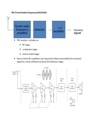
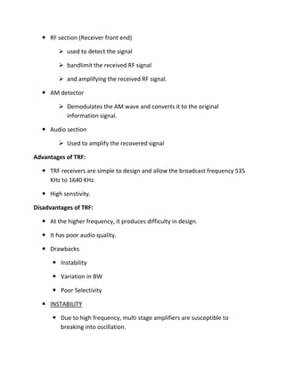
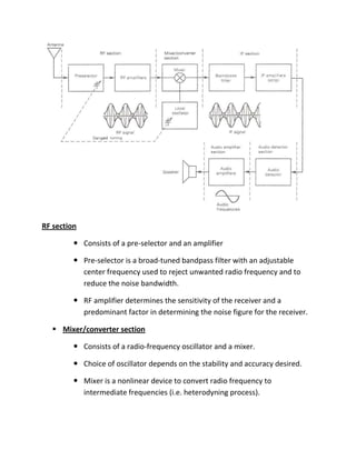
The document discusses radio receivers and their components and design. It describes the functions of radio receivers as intercepting modulated signals, selecting the desired signal, amplifying it, and demodulating it to recover the original signal. It explains the key components of receivers, including the RF amplifier, mixer, local oscillator, IF amplifier, and detector. It compares tuned radio frequency (TRF) receivers and superheterodyne receivers, noting that superheterodyne receivers overcome issues of TRF receivers like instability, bandwidth variation, and poor selectivity by downconverting RF signals to a lower intermediate frequency (IF). It also discusses characteristics of receivers like sensitivity, selectivity, and fidelity.
RF Carrier oscillator
To generate the carrier signal.
Usually a crystal-controlled oscillator is used.
Buffer amplifier
Low gain, high input impedance linear amplifier.
To isolate the oscillator from the high power amplifiers.
Modulator : can use either emitter collector modulation
Intermediate and final power amplifiers (pull-push modulators)
Required with low-level transmitters to maintain symmetry in the AM envelope
Coupling network
Matches output impedance of the final amplifier to the transmission line/antenn
Applications are in low-power, low-capacity systems : wireless intercoms, remote control units, pagers and short-range walkie-talkie
Modulating signal is processed similarly as in low-level transmitter except for the addition of power amplifier
Power amplifier
To provide higher power modulating signal necessary to achieve 100% modulation (carrier power is maximum at the high-level modulation point).
Same circuit as low-level transmitter for carrier oscillator, buffer and driver but with addition of power amplifier
A dipole antenna is the simplest antenna but its radiation characteristics are very good. The main drawback of a dipole antenna is very narrow bandwidth. The analysis of a dipole antenna can be performed with integration of Hertzian dipoles.
Broadside Array vs end-fire array
Higher directivity.
Provide increased directivity in
elevation and azimuth planes.
Generally used for reception.
Impedance match difficulty in
high power transmissions.
Variants are:
Horizontal Array of Dipoles
RCA Fishborne Antenna
Series Phase Array
This presentation will explain about the need for modulation in communication system. We made this presentation as our group assignment in Analog and Digital Communication System course in MIIT.
Wireless communications is a hot topic in technology today, driven by technologies like Wireless Networking, Cellular Telephony, Wireless Connectivity and Satellite Communications among others. Traditionally, wireless and RF communications has been one of the last bastions of analog engineering. With the advent of low cost digital, high speed integrated circuits, this too has become part of the digital domain. Although information transmitted today is largely digital high frequency signals whether digital or analog always behave like analog signals so having fundamental knowledge of this high frequency behavior is key.
Details: https://electronicsembeddedworld.blogspot.com/2018/06/performance-management-mcq.html
FM demodulation involves changing the frequency variations in a signal into amplitude variations at baseband, e.g. audio. There are several techniques and circuits that can be used each with its own advantages and disadvantages.
In any radio that is designed to receive frequency modulated signals there is some form of FM demodulator or detector. This circuit takes in frequency modulated RF signals and takes the modulation from the signal to output only the modulation that had been applied at the transmitter.
There are several types of FM detector / demodulator that can be used. Some types were more popular in the days when radios were made from discrete devices, but nowadays the PLL based detector and quadrature / coincidence detectors are the most widely used as they lend themselves to being incorporated into integrated circuits very easily...
A superheterodyne receiver, often shortened to superhet, is a type of radio receiver that uses frequency mixing to convert a received signal to a fixed intermediate frequency (IF) which can be more conveniently processed than the original carrier frequency. It was long believed to have been invented by US engineer Edwin Armstrong,
UiPath Test Automation using UiPath Test Suite series, part 4DianaGray10
Welcome to UiPath Test Automation using UiPath Test Suite series part 4. In this session, we will cover Test Manager overview along with SAP heatmap.
The UiPath Test Manager overview with SAP heatmap webinar offers a concise yet comprehensive exploration of the role of a Test Manager within SAP environments, coupled with the utilization of heatmaps for effective testing strategies.
Participants will gain insights into the responsibilities, challenges, and best practices associated with test management in SAP projects. Additionally, the webinar delves into the significance of heatmaps as a visual aid for identifying testing priorities, areas of risk, and resource allocation within SAP landscapes. Through this session, attendees can expect to enhance their understanding of test management principles while learning practical approaches to optimize testing processes in SAP environments using heatmap visualization techniques
What will you get from this session?
1. Insights into SAP testing best practices
2. Heatmap utilization for testing
3. Optimization of testing processes
4. Demo
Topics covered:
Execution from the test manager
Orchestrator execution result
Defect reporting
SAP heatmap example with demo
Speaker:
Deepak Rai, Automation Practice Lead, Boundaryless Group and UiPath MVP
State of ICS and IoT Cyber Threat Landscape Report 2024 previewPrayukth K V
The IoT and OT threat landscape report has been prepared by the Threat Research Team at Sectrio using data from Sectrio, cyber threat intelligence farming facilities spread across over 85 cities around the world. In addition, Sectrio also runs AI-based advanced threat and payload engagement facilities that serve as sinks to attract and engage sophisticated threat actors, and newer malware including new variants and latent threats that are at an earlier stage of development.
The latest edition of the OT/ICS and IoT security Threat Landscape Report 2024 also covers:
State of global ICS asset and network exposure
Sectoral targets and attacks as well as the cost of ransom
Global APT activity, AI usage, actor and tactic profiles, and implications
Rise in volumes of AI-powered cyberattacks
Major cyber events in 2024
Malware and malicious payload trends
Cyberattack types and targets
Vulnerability exploit attempts on CVEs
Attacks on counties – USA
Expansion of bot farms – how, where, and why
In-depth analysis of the cyber threat landscape across North America, South America, Europe, APAC, and the Middle East
Why are attacks on smart factories rising?
Cyber risk predictions
Axis of attacks – Europe
Systemic attacks in the Middle East
Download the full report from here:
https://sectrio.com/resources/ot-threat-landscape-reports/sectrio-releases-ot-ics-and-iot-security-threat-landscape-report-2024/
"Impact of front-end architecture on development cost", Viktor TurskyiFwdays
I have heard many times that architecture is not important for the front-end. Also, many times I have seen how developers implement features on the front-end just following the standard rules for a framework and think that this is enough to successfully launch the project, and then the project fails. How to prevent this and what approach to choose? I have launched dozens of complex projects and during the talk we will analyze which approaches have worked for me and which have not.
LF Energy Webinar: Electrical Grid Modelling and Simulation Through PowSyBl -...DanBrown980551
Do you want to learn how to model and simulate an electrical network from scratch in under an hour?
Then welcome to this PowSyBl workshop, hosted by Rte, the French Transmission System Operator (TSO)!
During the webinar, you will discover the PowSyBl ecosystem as well as handle and study an electrical network through an interactive Python notebook.
PowSyBl is an open source project hosted by LF Energy, which offers a comprehensive set of features for electrical grid modelling and simulation. Among other advanced features, PowSyBl provides:
- A fully editable and extendable library for grid component modelling;
- Visualization tools to display your network;
- Grid simulation tools, such as power flows, security analyses (with or without remedial actions) and sensitivity analyses;
The framework is mostly written in Java, with a Python binding so that Python developers can access PowSyBl functionalities as well.
What you will learn during the webinar:
- For beginners: discover PowSyBl's functionalities through a quick general presentation and the notebook, without needing any expert coding skills;
- For advanced developers: master the skills to efficiently apply PowSyBl functionalities to your real-world scenarios.
Epistemic Interaction - tuning interfaces to provide information for AI supportAlan Dix
Paper presented at SYNERGY workshop at AVI 2024, Genoa, Italy. 3rd June 2024
https://alandix.com/academic/papers/synergy2024-epistemic/
As machine learning integrates deeper into human-computer interactions, the concept of epistemic interaction emerges, aiming to refine these interactions to enhance system adaptability. This approach encourages minor, intentional adjustments in user behaviour to enrich the data available for system learning. This paper introduces epistemic interaction within the context of human-system communication, illustrating how deliberate interaction design can improve system understanding and adaptation. Through concrete examples, we demonstrate the potential of epistemic interaction to significantly advance human-computer interaction by leveraging intuitive human communication strategies to inform system design and functionality, offering a novel pathway for enriching user-system engagements.
Accelerate your Kubernetes clusters with Varnish CachingThijs Feryn
A presentation about the usage and availability of Varnish on Kubernetes. This talk explores the capabilities of Varnish caching and shows how to use the Varnish Helm chart to deploy it to Kubernetes.
This presentation was delivered at K8SUG Singapore. See https://feryn.eu/presentations/accelerate-your-kubernetes-clusters-with-varnish-caching-k8sug-singapore-28-2024 for more details.
JMeter webinar - integration with InfluxDB and GrafanaRTTS
Watch this recorded webinar about real-time monitoring of application performance. See how to integrate Apache JMeter, the open-source leader in performance testing, with InfluxDB, the open-source time-series database, and Grafana, the open-source analytics and visualization application.
In this webinar, we will review the benefits of leveraging InfluxDB and Grafana when executing load tests and demonstrate how these tools are used to visualize performance metrics.
Length: 30 minutes
Session Overview
-------------------------------------------
During this webinar, we will cover the following topics while demonstrating the integrations of JMeter, InfluxDB and Grafana:
- What out-of-the-box solutions are available for real-time monitoring JMeter tests?
- What are the benefits of integrating InfluxDB and Grafana into the load testing stack?
- Which features are provided by Grafana?
- Demonstration of InfluxDB and Grafana using a practice web application
To view the webinar recording, go to:
https://www.rttsweb.com/jmeter-integration-webinar
Connector Corner: Automate dynamic content and events by pushing a buttonDianaGray10
Here is something new! In our next Connector Corner webinar, we will demonstrate how you can use a single workflow to:
Create a campaign using Mailchimp with merge tags/fields
Send an interactive Slack channel message (using buttons)
Have the message received by managers and peers along with a test email for review
But there’s more:
In a second workflow supporting the same use case, you’ll see:
Your campaign sent to target colleagues for approval
If the “Approve” button is clicked, a Jira/Zendesk ticket is created for the marketing design team
But—if the “Reject” button is pushed, colleagues will be alerted via Slack message
Join us to learn more about this new, human-in-the-loop capability, brought to you by Integration Service connectors.
And...
Speakers:
Akshay Agnihotri, Product Manager
Charlie Greenberg, Host
Connector Corner: Automate dynamic content and events by pushing a button
Receivers
1. RECEIVERS :
Radio receiver is an electronic equipment which pick ups the desired signal, reject
the unwanted signal and demodulate the carrier signal to get back the original
modulating signal.
Function of Radio Receivers :
Intercept the incoming modulated signal
Select desired signal and reject unwanted signals
Amplify selected R.F signal
Detect modulated signal to get back original modulating signal
Amplify modulating frequency signal
Design of Receiver:
The radio receiver has to be cost effective
Requirements:
Has to work according to application as for AM or FM signals
Tune to and amplify desired radio station
Filter out all other stations
Demodulator has to work with all radio stations regardless of carrier
frequency
Classification of Radio Receivers:
Depending upon application
AM Receivers - receive broadcast of speech or music from AM transmitters
which operate on long wave, medium wave or short wave bands.
2. FM Receivers – receive broadcast programs from FM transmitters which
operate in VHF or UHF bands.
Communication Receivers - used for reception of telegraph and short wave
telephone signals.
Television Receivers - used to receive television broadcast in VHF or UHF
bands.
Radar Receivers – used to receive radio detection and ranging signals.
Depending upon fundamental aspects
Tuned Radio Frequency (TRF)Receivers
Super-heterodyne Receivers
Tuned Radio Frequency (TRF) Receiver:
Composed of RF amplifiers and detectors.
No frequency conversion
It is not often used.
Difficult to design tunable RF stages.
Difficult to obtain high gain RF amplifiers
Super-hetrodyne Receiver
Downconvert RF signal to lower IF frequency
Main amplifixcation takes place at IF
Communication Receiver
Downconvert RF signal to two IF frequency
3. TRF (Tuned Radio frequency) RECEIVER:
Tuned radio
frequency
amplifier
detector
A. F.
amplifier
Modulating
signal
TRF receiver includes an
RF stage
a detector stage
and an audio stage .
Two or three RF amplifiers are required to filter and amplify the received
signal to a level sufficient to drive the detector stage.
4. RF section (Receiver front end)
used to detect the signal
bandlimit the received RF signal
and amplifying the received RF signal.
AM detector
Demodulates the AM wave and converts it to the original
information signal.
Audio section
Used to amplify the recovered signal
Advantages of TRF:
TRF receivers are simple to design and allow the broadcast frequency 535
KHz to 1640 KHz.
High senstivity.
Disadvantages of TRF:
At the higher frequency, it produces difficulty in design.
It has poor audio quality.
Drawbacks
Instability
Variation in BW
Poor Selectivity
INSTABILITY
Due to high frequency, multi stage amplifiers are susceptible to
breaking into oscillation.
5. As gain of RF amplifier is very high ,a small feedback from output to
input with correct phase can lead to oscillations.
Correct phase means a positive feedback and it takes place due through
stray capacitances
As reactance of stray capacitances decreases at higher frequencies
resulting in increased feedback.
Forcing the device to work as an oscillator instead of an amplifier.
VARIATION IN BANDWIDTH
The bandwidth is inconsistent and varies with the center frequency
when tuned over a wide range of input frequencies.
As frequency increases, the bandwidth ( f/Q) increases. Thus, the
selectivity of the input filter changes over any appreciable range of
input frequencies.
POOR SELECTIVITY
The gains are not uniform over a very wide frequency range.
Due to higher frequencies ability to select desired signal is affected.
Due to these drawbacks TRF are rarely used.
SUPER HETRODYNE RECEIVER:
The shortcomings of the TRF receiver are overcome by the super heterodyne
receiver.
6. IF=fo- fs
RF
amplifie
fs
mixer
Local
oscillator
IF
amplifier
detector
AF
amplifie
r
Modulating
signal
fo
Ganged
tuning
Heterodyne – to mix two frequencies together in a nonlinear device or to
transmit one frequency to another using nonlinear mixing.
Also known as frequency conversion , high frequency down converted to
low frequency.(IF)
A super heterodyne receiver converts all incoming radio frequency (RF)
signals to a lower frequency known as an intermediate frequency (IF).
DRAWBACKS OVERCOMED:
Stability – as high frequency is down converted to IF the reactance of stray
capacitances will not decrease as it was at higher frequencies resulting in
increased feedback.
No variation in BW- as IF range is 438 to 465 KHz (in case of AM receivers) mostly
455KHz ,appropriate for Q limit (120).
Better selectivity- as no adjacent channels are picked due to variation in BW.
7. RF section
Consists of a pre-selector and an amplifier
Pre-selector is a broad-tuned bandpass filter with an adjustable
center frequency used to reject unwanted radio frequency and to
reduce the noise bandwidth.
RF amplifier determines the sensitivity of the receiver and a
predominant factor in determining the noise figure for the receiver.
Mixer/converter section
Consists of a radio-frequency oscillator and a mixer.
Choice of oscillator depends on the stability and accuracy desired.
Mixer is a nonlinear device to convert radio frequency to
intermediate frequencies (i.e. heterodyning process).
8. The shape of the envelope, the bandwidth and the original information contained
in the envelope remains unchanged although the carrier and sideband
frequencies are translated from RF to IF
IF section
Consists of a series of IF amplifiers and bandpassfilters to achieve
most of the receiver gain and selectivity.
The IF is always lower than the RF because it is easier and less
expensive to construct high-gain, stable amplifiers for low frequency
signals.
IF amplifiers are also less likely to oscillate than their RF
counterparts.
Detector section
To convert the IF signals back to the original source information (demodulation).
Can be as simple as a single diode or as complex as a PLL or balanced
demodulator.
Audio amplifier section
Comprises several cascaded audio amplifiers and one or more speakers
AGC ( Automatic Gain Control )
Adjust the IF amplifier gain according to signal level(to the average
amplitude signal almost constant).
AGC is a system by means of which the overall gain of radio receiver is
varied automatically with the variations in the strength of received signals,
to maintain the output constant.
AGC circuit is used to adjust and stabilize the frequency of local oscillator.
9. Types of AGC –
No AGC
Simple AGC
Delayed AGC
FREQUENCY CONVERSION in the mixer stage is identical to the frequency
conversion in the modulator except that in the receiver, the frequencies are
down-converted rather that up-converted.
In the mixer, RF signals are combined with the local oscillator
frequency
The local oscillator is designed such that its frequency of oscillation is
always above or below the desired RF carrier by an amount equal to
the IF center frequency.
Therefore the difference of RF and oscillator frequency is always
equal to the IF frequency
lo
fRF fIF
The adjustment for the center frequencyfof the pre-selector and the
local oscillator frequency are gang-tune (the two adjustments are
tied together so that single adjustment will change the center
frequency of the pre-selector and at the same time change the local
oscillator)
when local oscillator frequency is tuned above the RF – high side
injection
when local oscillator frequency is tuned below the RF – low side injection
Mathematically expressed :
High side injection
Low side injection
10. COMPARISON:
TRF Receiver
No frequency conversion
No IF frequency
Instability , variation in BW and
poor selectivity due to high
frequencies
Difficult to design tunable RF
stages.
Rarely used
Super hetrodyne Receiver
Frequency conversion
Downconvert RF signal to lower
IF frequency
No instability, variation in BW
and poor selectivity as IF
introduced.
Main amplifixcation takes place
at IF
Mostly used
CHARACTERISTICS OF RADIO RECEIVERS:
Sensitivity
Ability to amplify weak signals.
11. Minimum RF signal level that can be detected at the input to the
receiver and still produce a usable demodulated information signal.
Broadcast receivers/ radio receivers should have reasonably high
sensitivity so that it may have good response to the desired signal
But should not have excessively high sensitivity otherwise it will pick
up all undesired noise signals.
It is function of receiver gain and measures in decibels.
Sensitivity of a receiver is expressed in microvolts of the received
signal.
Typical sensitivity for commercial broadcast-band AM receiver is 50
μV.
Sensitivity of the receiver depends on :
Noise power present at the input to the receiver
Receiver noise figure
Bandwidth improvement factor of the receiver
The best way to improve the sensitivity is to reduce the noise level.
Selectivity
Selectivity of radio receiver is its ability to differentiate desired signal from
unwanted signals.
Selectivity is obtained by using tuned circuits, which are tuned to desired
frequency. The quality factor of these LC circuits determines the selectivity.
It is given by,
Q=XL/R
For better selectivity ‘Q’ should be high
Fidelity
Fidelity is defined as – a measure of the ability of a communication system
to produce an exact replica of the original source information at the output
of the receiver.
Any variations in the demodulated signal that are not in the original
information signal is considered as distortion.
12. Radio receiver should have high fidelity or accuracy.
Example- In an A.M. broadcast the maximum audio frequency is 5 KHz hence
receiver with good fidelity must produce entire frequency up to 5KHz
IMAGE FREQUENCY:
In radio reception using heterodyning in the tuning process, an undesired
input frequency that is capable of producing the same intermediate
frequency (IF) that the desired input frequency produces.
Image frequency – any frequency other than the selected radio frequency
carrier that will produce a cross-product frequency that is equal to the
intermediate frequency if allowed to enter a receiver and mix with the local
oscillator.
It is given by signal frequency plus twice the intermediate frequency
fsi = fs + 2fi
It is equivalent to a second radio frequency that will produce an IF that will
interfere with the IF from the desired radio frequency.
if the selected RF carrier and its image frequency enter a receiver at a
same time, they both mix with the local oscillator frequency and
produce different frequencies that are equal to the IF.
Consequently, two different stations are received and demodulated
simultaneously
The higher the IF, the farther away the image frequency is from the
desired radio frequency. Therefore, for better image frequency
rejection, a high IF is preferred.
However, the higher the IF, it is more difficult to build a stable amplifier with
high gain. i.e. there is a trade-off when selecting the IF for a radio receiver
(image frequency rejection vs IF gain andstability.
13. Once an image frequency has down-converted to IF, it cannot be removed.
In order to reject the image frequency, it has to be blocked prior to the mixer
stage. i.e. the bandwidth of the pre-selector must be sufficiently narrow to
prevent image frequency from entering the receiver.
CHOICE OF IF:
Very high IF will result in poor selectivity and poor adjacent channel
rejection
A high value of IF will result in tracking difficulties
At low values of IF image frequency rejection is poor. Also the selectivity
will be too sharp that cut off the sidebands