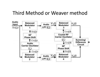
The document discusses three main methods for generating single-sideband suppressed carrier (SSB-SC) signals: the filter method, phase shift method, and Weaver method. The filter method uses a balanced modulator followed by a filter to remove the unwanted sideband. The phase shift method uses two balanced modulators with one audio input phase shifted 90 degrees. The Weaver method uses four balanced modulators, two audio filters, and two 90 degree phase shifters to generate the SSB signal without a filter or complex phase shifter.


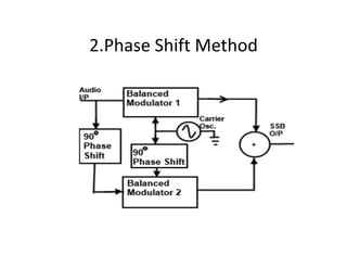
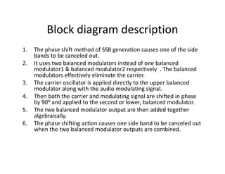
![• Let carrier signal is EcSinωct & Modulating signal (Audio Signal) EmSinωmt .
• Balanced modulator 1 produces the product of these two signals.
• Applying a trigonometric identity we get
EcSinωct * EmSinωmt = 1/2 [cos (ωc – ωm ) t - cos (ωc + ωm ) t] --- (1)
Similarly for Balanced modulator 2 carrier signal ( EcSinωct - 90o )= EcCos ωct
and Modulationg signal is applied with 90o phase shift (EmSinωmt - 90o )=
EmCos ωmt .
EcCos ωct * EmCos ωmt = 1/2 [cos (ωc – ωm ) t + cos (ωc + ωm ) t ] ----- (2)
Add (1) & (2)
The output of Adder is
V0= Cos (ωc – ωm ) t .
i.e Lower Side band only .](https://image.slidesharecdn.com/ssb-200328072013/85/Ssb-generation-method-10-320.jpg)