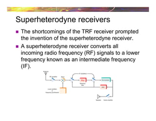
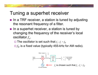
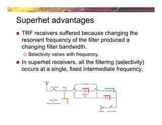
1) A superheterodyne receiver converts incoming radio frequencies to a fixed intermediate frequency (IF) through frequency mixing in order to improve selectivity. It does this by mixing the incoming signal with a local oscillator signal, producing the IF signal and other sum and difference frequencies.
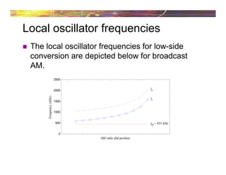
2) The local oscillator frequency is chosen such that the difference between it and the incoming signal frequency equals the IF. All filtering then occurs at this single IF, improving selectivity over a tunable radio frequency filter.
3) A potential issue is that the mixing process can also produce the "image frequency," which is equal to the local oscillator plus or minus twice the IF. A preselector filter before the mixer is used to filter out image frequencies