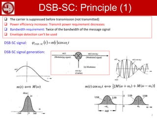
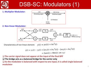
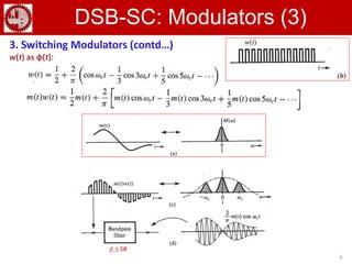
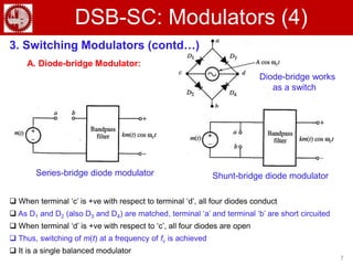
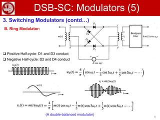
Communication Theory
Double-sideband Suppressed-Carrier
(DSB-SC)
2
DSB-SC: Principle (1)
    ttmt cSCDSB  cos
 The carrier is suppressed before transmission (not transmitted)
 Power efficiency increases: Transmit power requirement decreases
 Bandwidth requirement: Twice of the bandwidth of the message signal
 Envelope detection can’t be used
DSB-SC signal:
DSB-SC signal generation:
3
DSB-SC: Principle (2)
DSB-SC Demodulation:
          ttmtmttmttte cccSCDSB  2cos
2
1
2
1
coscos 2
 
After LPF:
Synchronous/ Coherent /
Homodyne Demodulator
(Detector)
4
DSB-SC: Modulators (1)
1. Multiplier Modulator:
2. Non-linear Modulator:
Characteristics of non-linear element:
 The carrier signal does not appear at the input of the final BPF
 The bridge acts as a balanced bridge for the carrier only
 As the modulator is balanced with respect to one input, it is called single balanced
modulator
5
DSB-SC: Modulators (2)
3. Switching Modulators:
 The multiplication operation is replaced by a simpler switching operation
 Multiplication can be achieved multiplying m(t) by any periodic signal φ(t) of the
fundamental frequency ωc
Thus,
6
DSB-SC: Modulators (3)
3. Switching Modulators (contd…)
w(t) as φ(t):
fc ≥ 2B
7
DSB-SC: Modulators (4)
3. Switching Modulators (contd…)
A. Diode-bridge Modulator:
Series-bridge diode modulator Shunt-bridge diode modulator
 When terminal ‘c’ is +ve with respect to terminal ‘d’, all four diodes conduct
 As D1 and D2 (also D3 and D4) are matched, terminal ‘a’ and terminal ‘b’ are short circuited
 When terminal ‘d’ is +ve with respect to ‘c’, all four diodes are open
 Thus, switching of m(t) at a frequency of fc is achieved
 It is a single balanced modulator
Diode-bridge works
as a switch
8
DSB-SC: Modulators (5)
3. Switching Modulators (contd…)
B. Ring Modulator:
 Positive Half-cycle: D1 and D3 conduct
 Negative Half-cycle: D2 and D4 conduct
(A double-balanced modulator)

Double SideBand Suppressed Carrier (DSB-SC)

  • 1.
  • 2.
    2 DSB-SC: Principle (1)    ttmt cSCDSB  cos  The carrier is suppressed before transmission (not transmitted)  Power efficiency increases: Transmit power requirement decreases  Bandwidth requirement: Twice of the bandwidth of the message signal  Envelope detection can’t be used DSB-SC signal: DSB-SC signal generation:
  • 3.
    3 DSB-SC: Principle (2) DSB-SCDemodulation:           ttmtmttmttte cccSCDSB  2cos 2 1 2 1 coscos 2   After LPF: Synchronous/ Coherent / Homodyne Demodulator (Detector)
  • 4.
    4 DSB-SC: Modulators (1) 1.Multiplier Modulator: 2. Non-linear Modulator: Characteristics of non-linear element:  The carrier signal does not appear at the input of the final BPF  The bridge acts as a balanced bridge for the carrier only  As the modulator is balanced with respect to one input, it is called single balanced modulator
  • 5.
    5 DSB-SC: Modulators (2) 3.Switching Modulators:  The multiplication operation is replaced by a simpler switching operation  Multiplication can be achieved multiplying m(t) by any periodic signal φ(t) of the fundamental frequency ωc Thus,
  • 6.
    6 DSB-SC: Modulators (3) 3.Switching Modulators (contd…) w(t) as φ(t): fc ≥ 2B
  • 7.
    7 DSB-SC: Modulators (4) 3.Switching Modulators (contd…) A. Diode-bridge Modulator: Series-bridge diode modulator Shunt-bridge diode modulator  When terminal ‘c’ is +ve with respect to terminal ‘d’, all four diodes conduct  As D1 and D2 (also D3 and D4) are matched, terminal ‘a’ and terminal ‘b’ are short circuited  When terminal ‘d’ is +ve with respect to ‘c’, all four diodes are open  Thus, switching of m(t) at a frequency of fc is achieved  It is a single balanced modulator Diode-bridge works as a switch
  • 8.
    8 DSB-SC: Modulators (5) 3.Switching Modulators (contd…) B. Ring Modulator:  Positive Half-cycle: D1 and D3 conduct  Negative Half-cycle: D2 and D4 conduct (A double-balanced modulator)