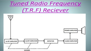
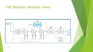
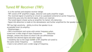
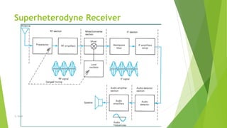
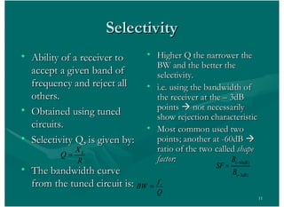
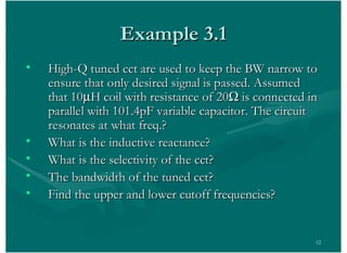
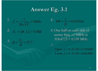
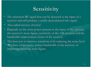
Radio Receivers
-Made By
Sumer Singh
-S. Singh
Outlines
 Radio Receivers:
 Functions & Classification of Radio Receivers,
 Tuned Radio Frequency (TRF) Receiver,
 Superheterodyne Receiver,
 Basic Elements,
 Receiver Characteristics,
 Frequency Mixers,
 AGC Characteristics.
-S. Singh
Radio Receiver
 radio receiver is an electronic device that
 picks up the desired signal,
 rejects the unwanted signal
 amplifies the desired signal
 demodulates the carrier signal to get back
the original modulation frequency signal.
-S. Singh
Features of Radio Receivers
 Simplicity of operation
 Good fidelity
 Good selectivity
 Average sensitivity
 Adaptability to different types of aerials
*We will discuss these later (last slide)
-S. Singh
Types Of Radio Receiver
 Crystal radio receiver
 Tuned radio frequency receiver
 Superheterodyne Receiver
-S. Singh
Crystal radio
 A crystal radio is the simplest kind of radio
 It needs no battery or power source
 It gets all of its power only from the radio wave.
-S. Singh
Tuned Radio Frequency Receiver
 one or more tuned radio frequency (RF)
 individually tuned to the station's frequency
 A tuned radio frequency receiver (or TRF receiver) is a type of radio
receiver that is usually composed of one or more tuned radio frequency (RF)
amplifier stages followed by a detector (demodulator) circuit to
extract the audio signal and an audio frequency amplifier. Popular in the
1920s, it could be tedious to operate because each stage must be individually
tuned to the station's frequency. By the mid 1930s it was
replaced by the superheterodyne receiver invented by Edwin Armstrong.
-S. Singh
How it works
 The classic TRF receivers of the 1920s and 30s
consisted of three sections:
 One or more tuned RF amplifier stages. These amplify
the signal of the desired station to a level sufficient to
drive the detector, while rejecting all other signals
picked up by the antenna
 a detector, which extracts the audio (modulation)
signal from the radio carrier signal by rectifying it
 optionally, but almost always included, one or more
audio amplifier stages which increase the power of the
audio signal.
-S. Singh
-S. Singh
TRF Receiver (Another view)
-S. Singh
Tuned RF Receiver (TRF)
– It is the earliest and simplest receiver design
– TRF consist of RF amplifiers stages, detector and audio amplifier stages
– The received signal is tuned by LC circuit to a passband centered at carrier frequency.
– Selectivity pass only the desired signal, others are rejected.
– The tuned signal is boost up by an amplifier for better info detection.
– Signal info detection is made at the demodulator and further amplified for the speaker output.
TRF has high sensitivity – ability to drive the speaker to an
acceptable level (to amplify).
– Disadvantages :-
• BW is inconsistent and varies with center frequency when
tuned over a wide range of input frequencies selectivity
changes, (means the extent to which a Rx can differentiate
between the desired signal and other signal).
• Instability due to the large number of RF amplifier all tuned to
the same center frequency oscillation.
• Gain is not uniform over a wide range of frequency.
-S. Singh
Superheterodyne Receiver
• Superhets was designed to overcome the problems in TRF.
• Complex circuitry compared to TRF but excellent
performance under many conditions
• Heterodyne mean:
– to mix 2 frequencies together in a nonlinear device or
– to translate one frequency to another using nonlinear device.
• Superhets concept:
– Rx tunes to desired signal and converts the signal to intermediate
frequency via a signal mixing circuit.
– Then IF signal is optimized to fully recovered the modulated info
signal.
-S. Singh
Superheterodyne Receiver
-S. Singh
Stages in Superhets
• RF Stage:
– Which takes the signal from the antenna and amplifies it to a level large
enough to be used in the following stages.
• Mixer and Local Oscillator:
– Converts the RF signal to IF signal.
• IF Stage:
– Further amplifies the signal and has bandwidth and passband shaping
appropriate for the received signal.
• Detector Stage:
– Recovers (demodulates) the info signal from the carrier.
• AF Stage:
– The received signal is amplified for loudspeaker or interconnections to
comm systems.
-S. Singh
RF Section
 Preselector stage
Broad tuned band pass filter with adjustable frequency that is tuned to
carrier frequency
Provide initial band limiting to prevent specific unwanted radio
frequency called image frequency from entering into receiver.
Reduces the noise bandwidth of the receiver and provides the initial
step toward reducing the over all receiver bandwidth to the
minimum bandwidth required to pass the information signal.
-S. Singh
Amplifier Stage
 It determines the sensitivity of the receiver.
 RF amplifier is the first active device in the network it is the primary
contributor to the noise. And it is the predominant factor in
determining the noise figure.
 Receiver may have one or more RF amplifier depending on the
desired sensitivity.
-S. Singh
Due to RF Amplifier
 Greater gain and better sensitivity
 Improved image frequency rejection
 Better signal to noise ratio
 Better selectivity
-S. Singh
Mixer stage
 Heterodyning takes place in the mixer stage.
 Radio frequencies are down converted to intermediate frequency
 Carrier and sidebands are translated to high frequencies without
effecting the envelope of message signal.
 Example: For AM Receiver
 Intermediate Frequency
fIF = fRF ± fLO
 RF=1000Khz
LO=1455Khz
fIF=2455, fIF=455
-S. Singh
-S. Singh
Frequency Conversion
-S. Singh
-S. Singh
flo =fsi+fif
→ fsi=flo-fif when signal frequency is
mixed with
oscillator
frequency
one of the by products is the
difference
Image frequency :It is any frequency other than the selected
radio frequency carrier that is allowed to enter
into the receiver and mix with the local
oscillator will produce cross product
frequencies that is equal to the intermediate
frequency.
frequency which is passed to the amplifier in the IF stage.
The frequency fim= flo+fsi the image frequency will also produce
fsi when mixed with fo .
For better image frequency rejection a high IF is preferred.
If intermediate frequency is high it is very difficult to design
stable amplifiers.
-S. Singh
-S. Singh
IF Choice
 If the IF is too high
Poor Selectivity and Poor adjacent channel rejection.
Tracking Difficulties.
 If the IF is too low
Image frequency rejection becomes poorer.
Selectivity too sharp and cutting off sidebands
Instability of oscillator will occur.
-S. Singh
Detector Section
 It contains detector and AGC or AVC
Detector: Rectifies the modulated signal, then filters out the 455
KHz. Leaving only the audio frequency or intelligence of 50 Hz – 20
KHz Which is sent to the AF amplifiers.
 Automatic Volume Control or gain control is taken at the detector
(demodulated and fed back to the first IF amplifier base). Required
to overcome atmospheric and terrain conditions that adversely affect
signal strength between the transmitter & receiver.
-S. Singh
AGC-Automatic Gain Control
--A dc level proportional to the received signal’s strength is
extracted from the detector stage and fed back to the IF and
sometimes to the mixer and/or the RF amplifier.
– This is the automatic gain control (AGC) level, which allows
relatively constant receiver output for widely variable received
signals.
The AGC help to maintain a constant output voltage level over a
wide range of RF input signal levels
– Without AGC, to not miss a weak station, you would probably
blow out your speaker while a weak station may not be audible.
– The received signal from the tuned station is constantly changing
as a result of changing weather and atmospheric conditions.
– The AGC allows you to listen to a station without constantly
monitoring the volume control.
-S. Singh
Amplifier Section
 The resultant audio signal is amplified in this section and fed into the
output device(ex: loudspeaker)……
In this section we have
Audio preamp stage
Audio driver stage
Audio push pull stage
-S. Singh
Selectivity
 It refers to the ability of a receiver to select a signal of desired frequency
while reject all others.
 The bandwidth of a tuned circuit is a measure of the selectivity .
-S. Singh
Sensitivity
 The ability of receiver to detect the weakest
possible signal is known as sensitivity
 It is expressed in microvolts or in decibels
 The sensitivity of receiver mostly depends on
the gain of the IF amplifiers.
 The minimum RF signal that can be detected at the input of a
receiver and still produce a usable demodulated info signal.
• Also called receiver threshold.
• Depends on the noise power present at the input of the receiver,
the receiver’s noise figure, sensitivity of the AM detector and the
bandwidth improvement factor of the receiver.
• The best way to improve sensitivity is by reducing the noise level
--reduce temperature, reduce bandwidth of the receiver, or
improving receiving noise figure.
-S. Singh
Fidelity
 The ability of receiver to reproduce
faithfully all the frequency components in
the baseband signal is called fidelity
 Fidelity is difficult to obtain in AM
receiver because good fidelity requires
more bandwidth
-S. Singh
11
SelectivitySelectivity
• Ability of a receiver toAbility of a receiver to
accept a given band ofaccept a given band of
frequency and reject allfrequency and reject all
others.others.
• Obtained using tunedObtained using tuned
circuits.circuits.
• Selectivity Q, is given by:Selectivity Q, is given by:
• The bandwidth curveThe bandwidth curve
from the tuned circuit is:from the tuned circuit is:
• Higher Q the narrower theHigher Q the narrower the
BW and the better theBW and the better the
selectivity.selectivity.
• i.e. using the bandwidth ofi.e. using the bandwidth of
the receiver at the – 3dBthe receiver at the – 3dB
pointspoints àà not necessarilynot necessarily
show rejection characteristicshow rejection characteristic
• Most common used twoMost common used two
points; another at -60dBpoints; another at -60dB àà
ratio of the two calledratio of the two called shapeshape
factor:factor:R
X
Q L
( 60 )
( 3 )
dB
dB
B
SF
B
Q
f
BW r
12
Example 3.1Example 3.1
• High-Q tuned cct are used to keep the BW narrow toHigh-Q tuned cct are used to keep the BW narrow to
ensure that only desired signal is passed. Assumedensure that only desired signal is passed. Assumed
that 10that 10 H coil with resistance of 20H coil with resistance of 20 is connected inis connected in
parallel with 101.4pF variable capacitor. The circuitparallel with 101.4pF variable capacitor. The circuit
resonates at what freq.?resonates at what freq.?
• What is the inductive reactance?What is the inductive reactance?
• What is the selectivity of the cct?What is the selectivity of the cct?
• The bandwidth of the tuned cct?The bandwidth of the tuned cct?
• Find the upper and lower cutoff frequencies?Find the upper and lower cutoff frequencies?
13
Answer Eg. 3.1Answer Eg. 3.1
1.1.
2.2.
3.3.
4.4.
5. One half on each side of5. One half on each side of
center freq. of 5MHz iscenter freq. of 5MHz is
318.47/2 = 0.159 MHz.318.47/2 = 0.159 MHz.
MHz
LC
fr 5
2
1
3142 LfX rL
7.15
R
X
Q L
kHz
Q
f
BW r
47.318
MHzf
MHzf
841.4159.05Lower,
159.5159.05Upper,
1
2
14
• The minimum RF signal that can be detected at the input of aThe minimum RF signal that can be detected at the input of a
receiver and still produce a usable demodulated info signal.receiver and still produce a usable demodulated info signal.
• Also called receiverAlso called receiver threshold.threshold.
• Depends on the noise power present at the input of the receiver,Depends on the noise power present at the input of the receiver,
the receiver’s noise figure, sensitivity of the AM detector and thethe receiver’s noise figure, sensitivity of the AM detector and the
bandwidth improvement factor of the receiver.bandwidth improvement factor of the receiver.
• The best way to improve sensitivity is by reducing the noise levelThe best way to improve sensitivity is by reducing the noise level
ààreduce temperature, reduce bandwidth of the receiver, orreduce temperature, reduce bandwidth of the receiver, or
improving receiving noise figure.improving receiving noise figure.
SensitivitySensitivity
15
• One way of reducing the noise level is by reducing the bandwidthOne way of reducing the noise level is by reducing the bandwidth
of the signalof the signal
• There is limitation for reducing the bandwidth to make sureThere is limitation for reducing the bandwidth to make sure
information is not lostinformation is not lost
• As RF bandwidth at the input of the receiver is higher than the IFAs RF bandwidth at the input of the receiver is higher than the IF
bandwidth at the output of the receiver, reducing the RFbandwidth at the output of the receiver, reducing the RF
bandwidth to IF bandwidth ratio effectively reducing the noisebandwidth to IF bandwidth ratio effectively reducing the noise
figure of the receiver, thus reducing the noisefigure of the receiver, thus reducing the noise
• Bandwidth improvement expressed mathematically asBandwidth improvement expressed mathematically as
• Noise figure improvement expressed asNoise figure improvement expressed as
NFNFimprovementimprovement = 10 log BI= 10 log BI
RF
IF
B
BI
B
Bandwidth Improvement FactorBandwidth Improvement Factor
16
Dynamic RangeDynamic Range
• The minimum input level necessary to discern a signalThe minimum input level necessary to discern a signal
and the input that will overdrive the receiver andand the input that will overdrive the receiver and
produce distortion.produce distortion.
• Minimum receive level is a function of front-end noise,Minimum receive level is a function of front-end noise,
noise figure and the desired signal quality.noise figure and the desired signal quality.
• Input that produce distortion is a function of the netInput that produce distortion is a function of the net
gain of the receiver.gain of the receiver.
• 1 dB compression point is used for the upper limit for1 dB compression point is used for the upper limit for
usefulness.usefulness.
17
FIGURE 3.7 Linear gain, 1-dB compression point, and third-order
intercept distortion for a typical amplifier
18
FidelityFidelity
• A measure of the ability of the receiver toA measure of the ability of the receiver to
produce, at the output of the receiver, an exactproduce, at the output of the receiver, an exact
replica of the original source information.replica of the original source information.
• Any amplitude, frequency or phase variationsAny amplitude, frequency or phase variations
present in the demodulated waveform that arepresent in the demodulated waveform that are
not included in the original signal are consider asnot included in the original signal are consider as
distortion.distortion.
19
Insertion LossInsertion Loss
• Loss occur when a signal enter the input of theLoss occur when a signal enter the input of the
receiver.receiver.
• Parameters associated with the frequencies thatParameters associated with the frequencies that
fall within the passband of a filter.fall within the passband of a filter.
• Defined as the ratio of the power transferred toDefined as the ratio of the power transferred to
the load with a filter in the circuit to the powerthe load with a filter in the circuit to the power
transferred to the load without a filter.transferred to the load without a filter.

Radio receiver sumer

  • 1.
  • 2.
    Outlines  Radio Receivers: Functions & Classification of Radio Receivers,  Tuned Radio Frequency (TRF) Receiver,  Superheterodyne Receiver,  Basic Elements,  Receiver Characteristics,  Frequency Mixers,  AGC Characteristics. -S. Singh
  • 3.
    Radio Receiver  radioreceiver is an electronic device that  picks up the desired signal,  rejects the unwanted signal  amplifies the desired signal  demodulates the carrier signal to get back the original modulation frequency signal. -S. Singh
  • 4.
    Features of RadioReceivers  Simplicity of operation  Good fidelity  Good selectivity  Average sensitivity  Adaptability to different types of aerials *We will discuss these later (last slide) -S. Singh
  • 5.
    Types Of RadioReceiver  Crystal radio receiver  Tuned radio frequency receiver  Superheterodyne Receiver -S. Singh
  • 6.
    Crystal radio  Acrystal radio is the simplest kind of radio  It needs no battery or power source  It gets all of its power only from the radio wave. -S. Singh
  • 7.
    Tuned Radio FrequencyReceiver  one or more tuned radio frequency (RF)  individually tuned to the station's frequency  A tuned radio frequency receiver (or TRF receiver) is a type of radio receiver that is usually composed of one or more tuned radio frequency (RF) amplifier stages followed by a detector (demodulator) circuit to extract the audio signal and an audio frequency amplifier. Popular in the 1920s, it could be tedious to operate because each stage must be individually tuned to the station's frequency. By the mid 1930s it was replaced by the superheterodyne receiver invented by Edwin Armstrong. -S. Singh
  • 8.
    How it works The classic TRF receivers of the 1920s and 30s consisted of three sections:  One or more tuned RF amplifier stages. These amplify the signal of the desired station to a level sufficient to drive the detector, while rejecting all other signals picked up by the antenna  a detector, which extracts the audio (modulation) signal from the radio carrier signal by rectifying it  optionally, but almost always included, one or more audio amplifier stages which increase the power of the audio signal. -S. Singh
  • 9.
  • 10.
    TRF Receiver (Anotherview) -S. Singh
  • 11.
    Tuned RF Receiver(TRF) – It is the earliest and simplest receiver design – TRF consist of RF amplifiers stages, detector and audio amplifier stages – The received signal is tuned by LC circuit to a passband centered at carrier frequency. – Selectivity pass only the desired signal, others are rejected. – The tuned signal is boost up by an amplifier for better info detection. – Signal info detection is made at the demodulator and further amplified for the speaker output. TRF has high sensitivity – ability to drive the speaker to an acceptable level (to amplify). – Disadvantages :- • BW is inconsistent and varies with center frequency when tuned over a wide range of input frequencies selectivity changes, (means the extent to which a Rx can differentiate between the desired signal and other signal). • Instability due to the large number of RF amplifier all tuned to the same center frequency oscillation. • Gain is not uniform over a wide range of frequency. -S. Singh
  • 12.
    Superheterodyne Receiver • Superhetswas designed to overcome the problems in TRF. • Complex circuitry compared to TRF but excellent performance under many conditions • Heterodyne mean: – to mix 2 frequencies together in a nonlinear device or – to translate one frequency to another using nonlinear device. • Superhets concept: – Rx tunes to desired signal and converts the signal to intermediate frequency via a signal mixing circuit. – Then IF signal is optimized to fully recovered the modulated info signal. -S. Singh
  • 13.
  • 14.
    Stages in Superhets •RF Stage: – Which takes the signal from the antenna and amplifies it to a level large enough to be used in the following stages. • Mixer and Local Oscillator: – Converts the RF signal to IF signal. • IF Stage: – Further amplifies the signal and has bandwidth and passband shaping appropriate for the received signal. • Detector Stage: – Recovers (demodulates) the info signal from the carrier. • AF Stage: – The received signal is amplified for loudspeaker or interconnections to comm systems. -S. Singh
  • 15.
    RF Section  Preselectorstage Broad tuned band pass filter with adjustable frequency that is tuned to carrier frequency Provide initial band limiting to prevent specific unwanted radio frequency called image frequency from entering into receiver. Reduces the noise bandwidth of the receiver and provides the initial step toward reducing the over all receiver bandwidth to the minimum bandwidth required to pass the information signal. -S. Singh
  • 16.
    Amplifier Stage  Itdetermines the sensitivity of the receiver.  RF amplifier is the first active device in the network it is the primary contributor to the noise. And it is the predominant factor in determining the noise figure.  Receiver may have one or more RF amplifier depending on the desired sensitivity. -S. Singh
  • 17.
    Due to RFAmplifier  Greater gain and better sensitivity  Improved image frequency rejection  Better signal to noise ratio  Better selectivity -S. Singh
  • 18.
    Mixer stage  Heterodyningtakes place in the mixer stage.  Radio frequencies are down converted to intermediate frequency  Carrier and sidebands are translated to high frequencies without effecting the envelope of message signal.  Example: For AM Receiver  Intermediate Frequency fIF = fRF ± fLO  RF=1000Khz LO=1455Khz fIF=2455, fIF=455 -S. Singh
  • 19.
  • 20.
  • 21.
  • 22.
    flo =fsi+fif → fsi=flo-fifwhen signal frequency is mixed with oscillator frequency one of the by products is the difference Image frequency :It is any frequency other than the selected radio frequency carrier that is allowed to enter into the receiver and mix with the local oscillator will produce cross product frequencies that is equal to the intermediate frequency. frequency which is passed to the amplifier in the IF stage. The frequency fim= flo+fsi the image frequency will also produce fsi when mixed with fo . For better image frequency rejection a high IF is preferred. If intermediate frequency is high it is very difficult to design stable amplifiers. -S. Singh
  • 23.
  • 24.
    IF Choice  Ifthe IF is too high Poor Selectivity and Poor adjacent channel rejection. Tracking Difficulties.  If the IF is too low Image frequency rejection becomes poorer. Selectivity too sharp and cutting off sidebands Instability of oscillator will occur. -S. Singh
  • 25.
    Detector Section  Itcontains detector and AGC or AVC Detector: Rectifies the modulated signal, then filters out the 455 KHz. Leaving only the audio frequency or intelligence of 50 Hz – 20 KHz Which is sent to the AF amplifiers.  Automatic Volume Control or gain control is taken at the detector (demodulated and fed back to the first IF amplifier base). Required to overcome atmospheric and terrain conditions that adversely affect signal strength between the transmitter & receiver. -S. Singh
  • 26.
    AGC-Automatic Gain Control --Adc level proportional to the received signal’s strength is extracted from the detector stage and fed back to the IF and sometimes to the mixer and/or the RF amplifier. – This is the automatic gain control (AGC) level, which allows relatively constant receiver output for widely variable received signals. The AGC help to maintain a constant output voltage level over a wide range of RF input signal levels – Without AGC, to not miss a weak station, you would probably blow out your speaker while a weak station may not be audible. – The received signal from the tuned station is constantly changing as a result of changing weather and atmospheric conditions. – The AGC allows you to listen to a station without constantly monitoring the volume control. -S. Singh
  • 27.
    Amplifier Section  Theresultant audio signal is amplified in this section and fed into the output device(ex: loudspeaker)…… In this section we have Audio preamp stage Audio driver stage Audio push pull stage -S. Singh
  • 28.
    Selectivity  It refersto the ability of a receiver to select a signal of desired frequency while reject all others.  The bandwidth of a tuned circuit is a measure of the selectivity . -S. Singh
  • 29.
    Sensitivity  The abilityof receiver to detect the weakest possible signal is known as sensitivity  It is expressed in microvolts or in decibels  The sensitivity of receiver mostly depends on the gain of the IF amplifiers.  The minimum RF signal that can be detected at the input of a receiver and still produce a usable demodulated info signal. • Also called receiver threshold. • Depends on the noise power present at the input of the receiver, the receiver’s noise figure, sensitivity of the AM detector and the bandwidth improvement factor of the receiver. • The best way to improve sensitivity is by reducing the noise level --reduce temperature, reduce bandwidth of the receiver, or improving receiving noise figure. -S. Singh
  • 30.
    Fidelity  The abilityof receiver to reproduce faithfully all the frequency components in the baseband signal is called fidelity  Fidelity is difficult to obtain in AM receiver because good fidelity requires more bandwidth -S. Singh
  • 31.
    11 SelectivitySelectivity • Ability ofa receiver toAbility of a receiver to accept a given band ofaccept a given band of frequency and reject allfrequency and reject all others.others. • Obtained using tunedObtained using tuned circuits.circuits. • Selectivity Q, is given by:Selectivity Q, is given by: • The bandwidth curveThe bandwidth curve from the tuned circuit is:from the tuned circuit is: • Higher Q the narrower theHigher Q the narrower the BW and the better theBW and the better the selectivity.selectivity. • i.e. using the bandwidth ofi.e. using the bandwidth of the receiver at the – 3dBthe receiver at the – 3dB pointspoints àà not necessarilynot necessarily show rejection characteristicshow rejection characteristic • Most common used twoMost common used two points; another at -60dBpoints; another at -60dB àà ratio of the two calledratio of the two called shapeshape factor:factor:R X Q L ( 60 ) ( 3 ) dB dB B SF B Q f BW r
  • 32.
    12 Example 3.1Example 3.1 •High-Q tuned cct are used to keep the BW narrow toHigh-Q tuned cct are used to keep the BW narrow to ensure that only desired signal is passed. Assumedensure that only desired signal is passed. Assumed that 10that 10 H coil with resistance of 20H coil with resistance of 20 is connected inis connected in parallel with 101.4pF variable capacitor. The circuitparallel with 101.4pF variable capacitor. The circuit resonates at what freq.?resonates at what freq.? • What is the inductive reactance?What is the inductive reactance? • What is the selectivity of the cct?What is the selectivity of the cct? • The bandwidth of the tuned cct?The bandwidth of the tuned cct? • Find the upper and lower cutoff frequencies?Find the upper and lower cutoff frequencies?
  • 33.
    13 Answer Eg. 3.1AnswerEg. 3.1 1.1. 2.2. 3.3. 4.4. 5. One half on each side of5. One half on each side of center freq. of 5MHz iscenter freq. of 5MHz is 318.47/2 = 0.159 MHz.318.47/2 = 0.159 MHz. MHz LC fr 5 2 1 3142 LfX rL 7.15 R X Q L kHz Q f BW r 47.318 MHzf MHzf 841.4159.05Lower, 159.5159.05Upper, 1 2
  • 34.
    14 • The minimumRF signal that can be detected at the input of aThe minimum RF signal that can be detected at the input of a receiver and still produce a usable demodulated info signal.receiver and still produce a usable demodulated info signal. • Also called receiverAlso called receiver threshold.threshold. • Depends on the noise power present at the input of the receiver,Depends on the noise power present at the input of the receiver, the receiver’s noise figure, sensitivity of the AM detector and thethe receiver’s noise figure, sensitivity of the AM detector and the bandwidth improvement factor of the receiver.bandwidth improvement factor of the receiver. • The best way to improve sensitivity is by reducing the noise levelThe best way to improve sensitivity is by reducing the noise level ààreduce temperature, reduce bandwidth of the receiver, orreduce temperature, reduce bandwidth of the receiver, or improving receiving noise figure.improving receiving noise figure. SensitivitySensitivity
  • 35.
    15 • One wayof reducing the noise level is by reducing the bandwidthOne way of reducing the noise level is by reducing the bandwidth of the signalof the signal • There is limitation for reducing the bandwidth to make sureThere is limitation for reducing the bandwidth to make sure information is not lostinformation is not lost • As RF bandwidth at the input of the receiver is higher than the IFAs RF bandwidth at the input of the receiver is higher than the IF bandwidth at the output of the receiver, reducing the RFbandwidth at the output of the receiver, reducing the RF bandwidth to IF bandwidth ratio effectively reducing the noisebandwidth to IF bandwidth ratio effectively reducing the noise figure of the receiver, thus reducing the noisefigure of the receiver, thus reducing the noise • Bandwidth improvement expressed mathematically asBandwidth improvement expressed mathematically as • Noise figure improvement expressed asNoise figure improvement expressed as NFNFimprovementimprovement = 10 log BI= 10 log BI RF IF B BI B Bandwidth Improvement FactorBandwidth Improvement Factor
  • 36.
    16 Dynamic RangeDynamic Range •The minimum input level necessary to discern a signalThe minimum input level necessary to discern a signal and the input that will overdrive the receiver andand the input that will overdrive the receiver and produce distortion.produce distortion. • Minimum receive level is a function of front-end noise,Minimum receive level is a function of front-end noise, noise figure and the desired signal quality.noise figure and the desired signal quality. • Input that produce distortion is a function of the netInput that produce distortion is a function of the net gain of the receiver.gain of the receiver. • 1 dB compression point is used for the upper limit for1 dB compression point is used for the upper limit for usefulness.usefulness.
  • 37.
    17 FIGURE 3.7 Lineargain, 1-dB compression point, and third-order intercept distortion for a typical amplifier
  • 38.
    18 FidelityFidelity • A measureof the ability of the receiver toA measure of the ability of the receiver to produce, at the output of the receiver, an exactproduce, at the output of the receiver, an exact replica of the original source information.replica of the original source information. • Any amplitude, frequency or phase variationsAny amplitude, frequency or phase variations present in the demodulated waveform that arepresent in the demodulated waveform that are not included in the original signal are consider asnot included in the original signal are consider as distortion.distortion.
  • 39.
    19 Insertion LossInsertion Loss •Loss occur when a signal enter the input of theLoss occur when a signal enter the input of the receiver.receiver. • Parameters associated with the frequencies thatParameters associated with the frequencies that fall within the passband of a filter.fall within the passband of a filter. • Defined as the ratio of the power transferred toDefined as the ratio of the power transferred to the load with a filter in the circuit to the powerthe load with a filter in the circuit to the power transferred to the load without a filter.transferred to the load without a filter.