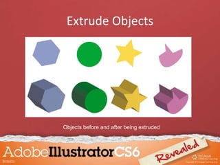
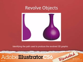
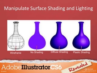
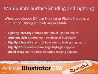
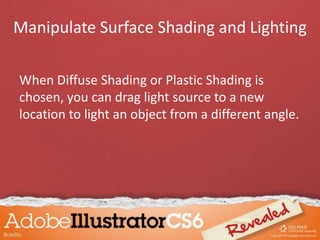
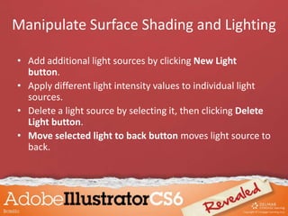
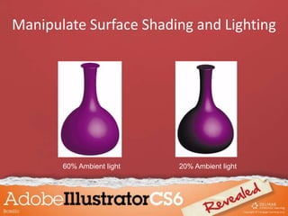
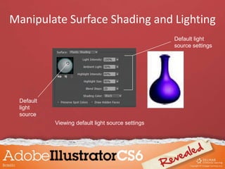
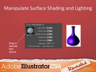
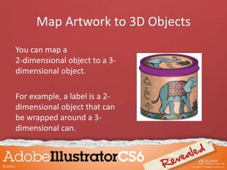
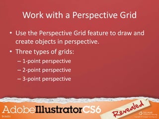
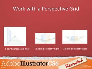
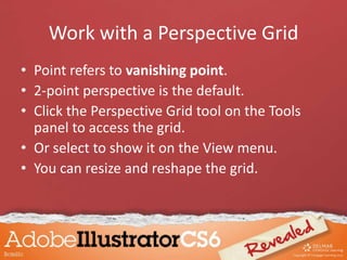
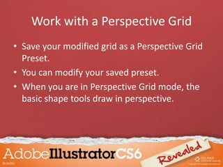
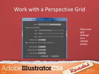
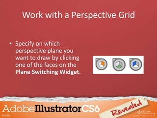
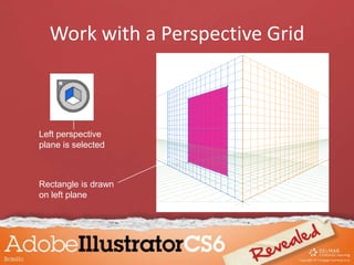
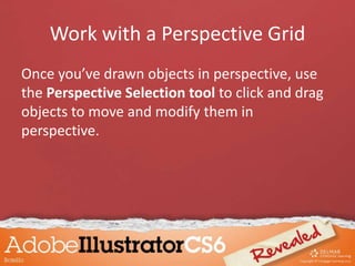
Chapter 10
Creating 3D Objects
Objectives
• Extrude objects
• Revolve objects
• Manipulate surface shading and lighting
• Map artwork to 3D objects
• Work with a perspective grid
Extrude Objects
• Extrude & Bevel effects apply three-
dimensional effects to two-dimensional
objects.
– Two-dimensional objects have two axes: X for
width and Y for height
– Three-dimensional objects have Z axis added
Extrude Objects
• Determine the degree of extrusion by
changing the Extrude Depth value in 3D
Extrude & Bevel Options dialog box.
• Use the Caps buttons in 3D Extrude & Bevel
Options dialog box to make objects appear
solid or hollow.
Extrude Objects
Objects before and after being extruded
Extrude Objects
Rotating 3D objects
• The 3D Extrude & Bevel Options dialog box
offers controls for rotating extruded objects.
• Rotate manually by dragging rotation cube.
Extrude Objects
• When you rotate the cube, values on the X, Y, and
Z axes update to reflect the changes made.
• Enter values in these boxes to rotate object at
specific angles.
• Once you extrude an object, you can view any
surface – front, back, left, or right.
Extrude Objects
Rotation
cube
X axis text box
Y axis text box
Z axis text box
Extrude Objects
Simple compound path Complex compound path
Simple compound path, extruded Complex compound path, extruded
Extrude Objects
• The Bevel menu offers ten predefined bevel
shapes you can apply to the edge of an
extruded object.
• You control the width of a bevel edge with the
Height slider.
Extrude Objects
Choose from 10
bevel shapes
Extrude Objects
Cove
RollingJaggy
Classic
Complex 2
Rounded
Bevel
shapes
applied to
edges
Extrude Objects
When Illustrator has difficulty rendering an
object with a beveled edge, a warning appears
in the 3D Extrude & Bevel Options dialog box.
Extrude Objects
• Sometimes there is no solution, but your best
bet is to reduce the bevel width.
• Decide how to apply bevel using the Bevel
Extent In and Bevel Extent Out buttons in 3D
Extrude & Bevel Options dialog box.
Extrude Objects
Bevel Extent Out button
Bevel Extent In button
Warning that beveled
edge may not have been
rendered well
Extrude Objects
Extruded text
Revolve Objects
Revolving an object “sweeps” a path in a circular
direction around the Y axis.
– Surface shading is applied automatically
– By default, object revolved around the vertical axis
that represents leftmost point
– The 3D Revolve Options dialog box offers an
option to revolve object from right edge
Revolve Objects
Revolving an object around
its left edge
Revolving an object around
its right edge
Revolve Objects
• A revolution occurs around the vertical axis.
– Starting path will depict half of the object you want
to revolve
• Once revolved, an object can be rotated by
using the 3D Revolve Options dialog box.
– It presents all surfaces of the graphic
Revolve Objects
Options for
revolving
objects
Revolve Objects
Identifying the path used to produce the revolved 3D graphic
Revolve Objects
A revolved graphic rotated four ways
Revolve Objects
• Apply the Revolve effect to multiple paths
simultaneously.
– Can be open or closed paths
• When Revolve effect is applied to multiple
paths, each path is revolved around its own
axis.
Revolve Objects
Revolving grouped objects
• When grouped, multiple paths are revolved
around a single axis.
• When multiple paths are grouped and
revolved, they will also rotate together.
Revolve Objects
Two grouped paths revolved around a single y-axis.
Object
before it is
revolved.
Object
after it is
revolved.
Revolve Objects
Four grouped paths after being revolved and rotated
Revolve Objects
Increasing the
Offset value in
the 3D Revolve
Options dialog
box increases
how far from the
Y axis the object
is revolved.
Enter
offset
value
here
Revolve Objects
Object revolved with a 90-
point offset from its Y-axis
Rotated object shows
90-point offset more clearly
Manipulate Surface Shading and Lighting
When you apply the Extrude & Bevel effect or
Revolve effect, surface shading and lighting is
applied automatically but can be manipulated.
• When you revolve an object, four surface
shadings are available:
– Wireframe
– No Shading
– Diffuse Shading
– Plastic Shading
Manipulate Surface Shading and Lighting
Wireframe No Shading Diffuse Shading Plastic Shading
Manipulate Surface Shading and Lighting
When you choose Diffuse Shading or Plastic Shading, a
number of lighting controls are available.
• Lighting Intensity controls strength of light on object.
• Ambient Light determines how object is lit globally.
• Highlight Intensity controls how intense highlight appears.
• Highlight Size controls how large highlights appear.
• Blend Steps controls how smoothly shading appears.
Manipulate Surface Shading and Lighting
When Diffuse Shading or Plastic Shading is
chosen, you can drag light source to a new
location to light an object from a different angle.
Manipulate Surface Shading and Lighting
• Add additional light sources by clicking New Light
button.
• Apply different light intensity values to individual light
sources.
• Delete a light source by selecting it, then clicking Delete
Light button.
• Move selected light to back button moves light source to
back.
Manipulate Surface Shading and Lighting
20% Ambient light60% Ambient light
Manipulate Surface Shading and Lighting
Default
light
source
Viewing default light source settings
Default light
source settings
Manipulate Surface Shading and Lighting
Drag to
relocate
light
source
Manipulate Surface Shading and Lighting
Map Artwork to 3D Objects
You can map a
2-dimensional object to a 3-
dimensional object.
For example, a label is a 2-
dimensional object that can
be wrapped around a 3-
dimensional can.
Map Artwork to 3D Objects
• First convert 2D object to symbol.
• Select a 3D object.
• Click Map Art in the 3D Revolve Options
dialog box.
Map Artwork to 3D Objects
Objects to be used for mapping
Map Artwork to 3D Objects
• In the Map Art dialog box choose which
surface you want to map the art on.
• When you click a surface button, active
surface is shown in red wireframe on 3D
object.
Map Artwork to 3D Objects
Surface buttons
Interior of curved lines represents visible surface (1 of 4)
Map Artwork to 3D Objects
• Grid pattern represents the complete surface
of the object.
• Includes the entire surface around the object
that you may not see.
Map Artwork to 3D Objects
• Once surface chosen, choose symbol to be
mapped by clicking the Symbol list arrow.
– Symbol artwork is centered on grid.
– Drag artwork so it completely covers curved lines
– Once artwork is mapped, it reshapes itself to the
three-dimensional object
Map Artwork to 3D Objects
Wrapping
Paper symbol
selected
Map Artwork to 3D objects
Symbol
artwork is
mapped to
3-D
object.
Work with a Perspective Grid
• Use the Perspective Grid feature to draw and
create objects in perspective.
• Three types of grids:
– 1-point perspective
– 2-point perspective
– 3-point perspective
Work with a Perspective Grid
1-point perspective grid 2-point perspective grid 3-point perspective grid
Work with a Perspective Grid
• Point refers to vanishing point.
• 2-point perspective is the default.
• Click the Perspective Grid tool on the Tools
panel to access the grid.
• Or select to show it on the View menu.
• You can resize and reshape the grid.
• Save your modified grid as a Perspective Grid
Preset.
• You can modify your saved preset.
• When you are in Perspective Grid mode, the
basic shape tools draw in perspective.
Work with a Perspective Grid
Save your
grid
settings
as a
named
preset
Work with a Perspective Grid
• Specify on which
perspective plane you
want to draw by clicking
one of the faces on the
Plane Switching Widget.
Work with a Perspective Grid
Left perspective
plane is selected
Rectangle is drawn
on left plane
Work with a Perspective Grid
Once you’ve drawn objects in perspective, use
the Perspective Selection tool to click and drag
objects to move and modify them in
perspective.
Work with a Perspective Grid
Three copies of an
ellipse dragged
and dropped with
the Perspective
Selection tool.

Chapter 10

  • 1.
  • 2.
    Objectives • Extrude objects •Revolve objects • Manipulate surface shading and lighting • Map artwork to 3D objects • Work with a perspective grid
  • 3.
    Extrude Objects • Extrude& Bevel effects apply three- dimensional effects to two-dimensional objects. – Two-dimensional objects have two axes: X for width and Y for height – Three-dimensional objects have Z axis added
  • 4.
    Extrude Objects • Determinethe degree of extrusion by changing the Extrude Depth value in 3D Extrude & Bevel Options dialog box. • Use the Caps buttons in 3D Extrude & Bevel Options dialog box to make objects appear solid or hollow.
  • 5.
    Extrude Objects Objects beforeand after being extruded
  • 6.
    Extrude Objects Rotating 3Dobjects • The 3D Extrude & Bevel Options dialog box offers controls for rotating extruded objects. • Rotate manually by dragging rotation cube.
  • 7.
    Extrude Objects • Whenyou rotate the cube, values on the X, Y, and Z axes update to reflect the changes made. • Enter values in these boxes to rotate object at specific angles. • Once you extrude an object, you can view any surface – front, back, left, or right.
  • 8.
    Extrude Objects Rotation cube X axistext box Y axis text box Z axis text box
  • 9.
    Extrude Objects Simple compoundpath Complex compound path Simple compound path, extruded Complex compound path, extruded
  • 10.
    Extrude Objects • TheBevel menu offers ten predefined bevel shapes you can apply to the edge of an extruded object. • You control the width of a bevel edge with the Height slider.
  • 11.
  • 12.
  • 13.
    Extrude Objects When Illustratorhas difficulty rendering an object with a beveled edge, a warning appears in the 3D Extrude & Bevel Options dialog box.
  • 14.
    Extrude Objects • Sometimesthere is no solution, but your best bet is to reduce the bevel width. • Decide how to apply bevel using the Bevel Extent In and Bevel Extent Out buttons in 3D Extrude & Bevel Options dialog box.
  • 15.
    Extrude Objects Bevel ExtentOut button Bevel Extent In button Warning that beveled edge may not have been rendered well
  • 16.
  • 17.
    Revolve Objects Revolving anobject “sweeps” a path in a circular direction around the Y axis. – Surface shading is applied automatically – By default, object revolved around the vertical axis that represents leftmost point – The 3D Revolve Options dialog box offers an option to revolve object from right edge
  • 18.
    Revolve Objects Revolving anobject around its left edge Revolving an object around its right edge
  • 19.
    Revolve Objects • Arevolution occurs around the vertical axis. – Starting path will depict half of the object you want to revolve • Once revolved, an object can be rotated by using the 3D Revolve Options dialog box. – It presents all surfaces of the graphic
  • 20.
  • 21.
    Revolve Objects Identifying thepath used to produce the revolved 3D graphic
  • 22.
    Revolve Objects A revolvedgraphic rotated four ways
  • 23.
    Revolve Objects • Applythe Revolve effect to multiple paths simultaneously. – Can be open or closed paths • When Revolve effect is applied to multiple paths, each path is revolved around its own axis.
  • 24.
    Revolve Objects Revolving groupedobjects • When grouped, multiple paths are revolved around a single axis. • When multiple paths are grouped and revolved, they will also rotate together.
  • 25.
    Revolve Objects Two groupedpaths revolved around a single y-axis. Object before it is revolved. Object after it is revolved.
  • 26.
    Revolve Objects Four groupedpaths after being revolved and rotated
  • 27.
    Revolve Objects Increasing the Offsetvalue in the 3D Revolve Options dialog box increases how far from the Y axis the object is revolved. Enter offset value here
  • 28.
    Revolve Objects Object revolvedwith a 90- point offset from its Y-axis Rotated object shows 90-point offset more clearly
  • 29.
    Manipulate Surface Shadingand Lighting When you apply the Extrude & Bevel effect or Revolve effect, surface shading and lighting is applied automatically but can be manipulated.
  • 30.
    • When yourevolve an object, four surface shadings are available: – Wireframe – No Shading – Diffuse Shading – Plastic Shading Manipulate Surface Shading and Lighting
  • 31.
    Wireframe No ShadingDiffuse Shading Plastic Shading Manipulate Surface Shading and Lighting
  • 32.
    When you chooseDiffuse Shading or Plastic Shading, a number of lighting controls are available. • Lighting Intensity controls strength of light on object. • Ambient Light determines how object is lit globally. • Highlight Intensity controls how intense highlight appears. • Highlight Size controls how large highlights appear. • Blend Steps controls how smoothly shading appears. Manipulate Surface Shading and Lighting
  • 33.
    When Diffuse Shadingor Plastic Shading is chosen, you can drag light source to a new location to light an object from a different angle. Manipulate Surface Shading and Lighting
  • 34.
    • Add additionallight sources by clicking New Light button. • Apply different light intensity values to individual light sources. • Delete a light source by selecting it, then clicking Delete Light button. • Move selected light to back button moves light source to back. Manipulate Surface Shading and Lighting
  • 35.
    20% Ambient light60%Ambient light Manipulate Surface Shading and Lighting
  • 36.
    Default light source Viewing default lightsource settings Default light source settings Manipulate Surface Shading and Lighting
  • 37.
  • 38.
    Map Artwork to3D Objects You can map a 2-dimensional object to a 3- dimensional object. For example, a label is a 2- dimensional object that can be wrapped around a 3- dimensional can.
  • 39.
    Map Artwork to3D Objects • First convert 2D object to symbol. • Select a 3D object. • Click Map Art in the 3D Revolve Options dialog box.
  • 40.
    Map Artwork to3D Objects Objects to be used for mapping
  • 41.
    Map Artwork to3D Objects • In the Map Art dialog box choose which surface you want to map the art on. • When you click a surface button, active surface is shown in red wireframe on 3D object.
  • 42.
    Map Artwork to3D Objects Surface buttons Interior of curved lines represents visible surface (1 of 4)
  • 43.
    Map Artwork to3D Objects • Grid pattern represents the complete surface of the object. • Includes the entire surface around the object that you may not see.
  • 44.
    Map Artwork to3D Objects • Once surface chosen, choose symbol to be mapped by clicking the Symbol list arrow. – Symbol artwork is centered on grid. – Drag artwork so it completely covers curved lines – Once artwork is mapped, it reshapes itself to the three-dimensional object
  • 45.
    Map Artwork to3D Objects Wrapping Paper symbol selected
  • 46.
    Map Artwork to3D objects Symbol artwork is mapped to 3-D object.
  • 47.
    Work with aPerspective Grid • Use the Perspective Grid feature to draw and create objects in perspective. • Three types of grids: – 1-point perspective – 2-point perspective – 3-point perspective
  • 48.
    Work with aPerspective Grid 1-point perspective grid 2-point perspective grid 3-point perspective grid
  • 49.
    Work with aPerspective Grid • Point refers to vanishing point. • 2-point perspective is the default. • Click the Perspective Grid tool on the Tools panel to access the grid. • Or select to show it on the View menu. • You can resize and reshape the grid.
  • 50.
    • Save yourmodified grid as a Perspective Grid Preset. • You can modify your saved preset. • When you are in Perspective Grid mode, the basic shape tools draw in perspective. Work with a Perspective Grid
  • 51.
    Work with aPerspective Grid Save your grid settings as a named preset
  • 52.
    Work with aPerspective Grid • Specify on which perspective plane you want to draw by clicking one of the faces on the Plane Switching Widget.
  • 53.
    Work with aPerspective Grid Left perspective plane is selected Rectangle is drawn on left plane
  • 54.
    Work with aPerspective Grid Once you’ve drawn objects in perspective, use the Perspective Selection tool to click and drag objects to move and modify them in perspective.
  • 55.
    Work with aPerspective Grid Three copies of an ellipse dragged and dropped with the Perspective Selection tool.