Download as PDF, PPTX


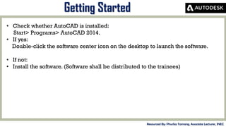


This document provides a training summary on AutoCAD. It begins with an introduction to AutoCAD, including what it is, who developed it, and its uses. It then covers the different versions of AutoCAD over time. The main content sections include explanations and exercises on how to get started with AutoCAD, how to draw basic shapes and edit objects, set up drawings, add dimensions, change object properties like color and line weight, and work with layers. Trainees are guided through hands-on practice with the various drawing, editing and formatting tools in AutoCAD.