Downloaded 7,643 times
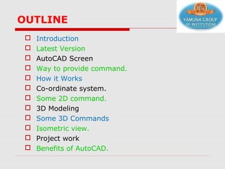
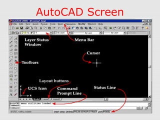
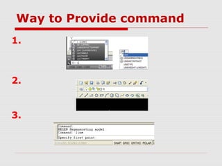
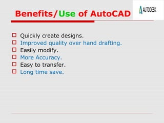


This document presents an outline for a presentation on AutoCAD 2013. It will cover the introduction to AutoCAD including its history and latest version. It will demonstrate the AutoCAD screen and interface. It will explain the coordinate system and demonstrate various 2D and 3D commands. Examples of 2D and 3D modeling projects will be shown. The presentation will conclude by discussing the benefits of using AutoCAD software.