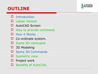
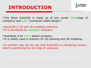
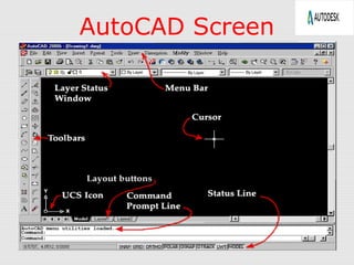
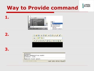
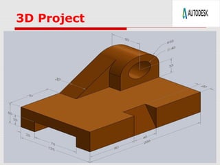
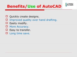
PRESENTATION
on
AutoCAD 2013
Submitted By :-
Bittu kumar yadav
1314140019
MECHANICAL (4th
year)
OUTLINE
 Introduction
 Latest Version
 AutoCAD Screen
 Way to provide command.
 How it Works
 Co-ordinate system.
 Some 2D command.
 3D Modeling
 Some 3D Commands
 Isometric view.
 Project work
 Benefits of AutoCAD.
The Word AutoCAD is made up of two words “Auto(logo of
company)”and CAD “(computer aided design)”.
AutoCAD is 2D and 3D modeling software.
It is developed by Autodesk company.
Autodesk is an U.S.A based company.
It is widely used in industry for 2D drawing and 3D modeling.
In another way we can say that AutoCAD is a designing course ,
which is performed by the help of computer.
INTRODUCTION
Version of AutoCAD
 AutoCAD software was firstly launched by Autodesk
company in Dec. 1982.
 It comes in India in 1988.
 The first version of AutoCAD was R1 after that
R2,R3,R4…………… and so on.
 In 2000,Autodesk launched a version of AutoCAD
2000 after that 2001,2002…… so on.
 This time, we have the latest version of AutoCAD is
2014,which is launched on 27th
march 2013.
 Latest version is easy to use and over come the
difficulties of old version.
AutoCAD Screen
Way to Provide command
1.
2.
3.
HOW AutoCAD WORKS
 There is a co-ordinate system used in AutoCAD.
 Every drawing shows its co-ordinate.
 In above next slide the line shows its co-ordinate that is ( 9,6 ) and
(-10,-4).
 There is so many commands like copy, move ,rotate ,mirror in 2D,
path array , rectangular array, polar array & more.
 Different types of drawing can be made in the same time by using a
command that is LAYER.
 Using line , arc , circle , rectangle , ellipse & polygon , so many
drawing of different type can be made.
CO-Ordinate System
 Every thing that we draw in AutoCAD is exact.
 All object drawn on screen is based on simple X-Y co-
ordinate system.
 In AutoCAD it is known as world co-ordinate system
(WCS).
 We are drawing a line, so we have two points A(-10,-4)
and B(9,6). As shown in figure.
The UCS and WCS
 The AutoCAD world is 3 dimensional. However, if we want to draw a
2d object, such as a plan or a section, we will use only 2 dimensions
(x and y).
 WCS (world coordinate system) is the imaginary plane that is parallel
to the ground. It is the default coordinate system.
 Modifications made to the World Coordinate System (WCS) result in a
User Coordinate System (UCS). It is the plane that you work on. It
enables the user to draw 3 dimensional objects.
 To create a new UCS, type ucs on the command window, then say
New and specify 3 points on your new UCS plane.
Some 2D Commands
 Chamfer 2. Fillet
 Copy 4. Mirror
2D Commands
 Scale 2. Array
 Extend 4.Join
Hatching
 Hatching is used to add shaded patterns to objects and
shapes within an Autocad drawing. Hatch patterns can
be used to indicate a material to be used, such as a
concrete hatch.
 You will pick:
 Pattern
 Scale
 Angle
 points
 Solids contain the “mass properties” of 3D
objects.
 You can use the Solids toolbar for readily
accessible objects
 Box
 Cylinder
 Wedge
 You can use the Boolean operations of more
complicated shapes.
 Union (join two solids)
 Subtract (carve out the second solid from the first)
 Intersection (only the common area)
3D Modeling
 Torus
 Cone
 Sphere
Some 3D Object
3D Commands
EXTRUDE
Extrusions can extend in the Z direction or be set to taper or follow a path.
You can extrude an open or closed object to create a 3D surface or solid.
Vscurrent
It is used for setting of view style of diagram, which may be…..
1.2D wireframe.
2.Realistic.
3.3D Hidden.
3D Commands
REVOLVE
Creates a 3D solid or surface by REVOLVE an object around an axis.
SWEEP
Creates A solid or surface by sweeping an open or closed, planar or
non-planar curve (profile) along an open or closed path. Open curves create
surfaces and closed curves create solids or surfaces.
Use of Extrude Command
 If you “Extrude” a surface into the third dimension, you
simply add a thickness in section. This basically is same as
creating a “solid” object .
Extrude 5
units 5 units
Extrude -4
units
4 units
2D Project (1)
2D Project Work (2)
3D Project
Benefits/Use of AutoCAD
 Quickly create designs.
 Improved quality over hand drafting.
 Easily modify.
 More Accuracy.
 Easy to transfer.
 Long time save.
AUTO-CAD Mechanical project PPT by Bittu kumar

AUTO-CAD Mechanical project PPT by Bittu kumar

  • 1.
    PRESENTATION on AutoCAD 2013 Submitted By:- Bittu kumar yadav 1314140019 MECHANICAL (4th year)
  • 2.
    OUTLINE  Introduction  LatestVersion  AutoCAD Screen  Way to provide command.  How it Works  Co-ordinate system.  Some 2D command.  3D Modeling  Some 3D Commands  Isometric view.  Project work  Benefits of AutoCAD.
  • 3.
    The Word AutoCADis made up of two words “Auto(logo of company)”and CAD “(computer aided design)”. AutoCAD is 2D and 3D modeling software. It is developed by Autodesk company. Autodesk is an U.S.A based company. It is widely used in industry for 2D drawing and 3D modeling. In another way we can say that AutoCAD is a designing course , which is performed by the help of computer. INTRODUCTION
  • 4.
    Version of AutoCAD AutoCAD software was firstly launched by Autodesk company in Dec. 1982.  It comes in India in 1988.  The first version of AutoCAD was R1 after that R2,R3,R4…………… and so on.  In 2000,Autodesk launched a version of AutoCAD 2000 after that 2001,2002…… so on.  This time, we have the latest version of AutoCAD is 2014,which is launched on 27th march 2013.  Latest version is easy to use and over come the difficulties of old version.
  • 5.
  • 6.
    Way to Providecommand 1. 2. 3.
  • 7.
    HOW AutoCAD WORKS There is a co-ordinate system used in AutoCAD.  Every drawing shows its co-ordinate.  In above next slide the line shows its co-ordinate that is ( 9,6 ) and (-10,-4).  There is so many commands like copy, move ,rotate ,mirror in 2D, path array , rectangular array, polar array & more.  Different types of drawing can be made in the same time by using a command that is LAYER.  Using line , arc , circle , rectangle , ellipse & polygon , so many drawing of different type can be made.
  • 8.
    CO-Ordinate System  Everything that we draw in AutoCAD is exact.  All object drawn on screen is based on simple X-Y co- ordinate system.  In AutoCAD it is known as world co-ordinate system (WCS).  We are drawing a line, so we have two points A(-10,-4) and B(9,6). As shown in figure.
  • 9.
    The UCS andWCS  The AutoCAD world is 3 dimensional. However, if we want to draw a 2d object, such as a plan or a section, we will use only 2 dimensions (x and y).  WCS (world coordinate system) is the imaginary plane that is parallel to the ground. It is the default coordinate system.  Modifications made to the World Coordinate System (WCS) result in a User Coordinate System (UCS). It is the plane that you work on. It enables the user to draw 3 dimensional objects.  To create a new UCS, type ucs on the command window, then say New and specify 3 points on your new UCS plane.
  • 10.
    Some 2D Commands Chamfer 2. Fillet  Copy 4. Mirror
  • 11.
    2D Commands  Scale2. Array  Extend 4.Join
  • 12.
    Hatching  Hatching isused to add shaded patterns to objects and shapes within an Autocad drawing. Hatch patterns can be used to indicate a material to be used, such as a concrete hatch.  You will pick:  Pattern  Scale  Angle  points
  • 13.
     Solids containthe “mass properties” of 3D objects.  You can use the Solids toolbar for readily accessible objects  Box  Cylinder  Wedge  You can use the Boolean operations of more complicated shapes.  Union (join two solids)  Subtract (carve out the second solid from the first)  Intersection (only the common area) 3D Modeling  Torus  Cone  Sphere
  • 14.
  • 15.
    3D Commands EXTRUDE Extrusions canextend in the Z direction or be set to taper or follow a path. You can extrude an open or closed object to create a 3D surface or solid. Vscurrent It is used for setting of view style of diagram, which may be….. 1.2D wireframe. 2.Realistic. 3.3D Hidden.
  • 16.
    3D Commands REVOLVE Creates a3D solid or surface by REVOLVE an object around an axis. SWEEP Creates A solid or surface by sweeping an open or closed, planar or non-planar curve (profile) along an open or closed path. Open curves create surfaces and closed curves create solids or surfaces.
  • 17.
    Use of ExtrudeCommand  If you “Extrude” a surface into the third dimension, you simply add a thickness in section. This basically is same as creating a “solid” object . Extrude 5 units 5 units Extrude -4 units 4 units
  • 18.
  • 19.
  • 20.
  • 21.
    Benefits/Use of AutoCAD Quickly create designs.  Improved quality over hand drafting.  Easily modify.  More Accuracy.  Easy to transfer.  Long time save.