Downloaded 448 times
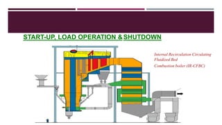
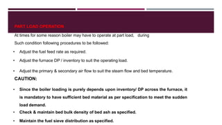


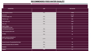
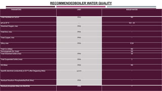

This document provides a comprehensive guide on the startup, load operation, and shutdown procedures for an internal recirculation circulating fluidized bed combustion (IR-CFBC) boiler. It outlines detailed steps for cold startup, fuel feeding, burner operation, bed material filling, and safety checks, along with precautions to ensure safe operations. Additionally, it addresses normal and emergency shutdown procedures to maintain safety and efficiency during boiler operation.