Download as PDF, PPTX

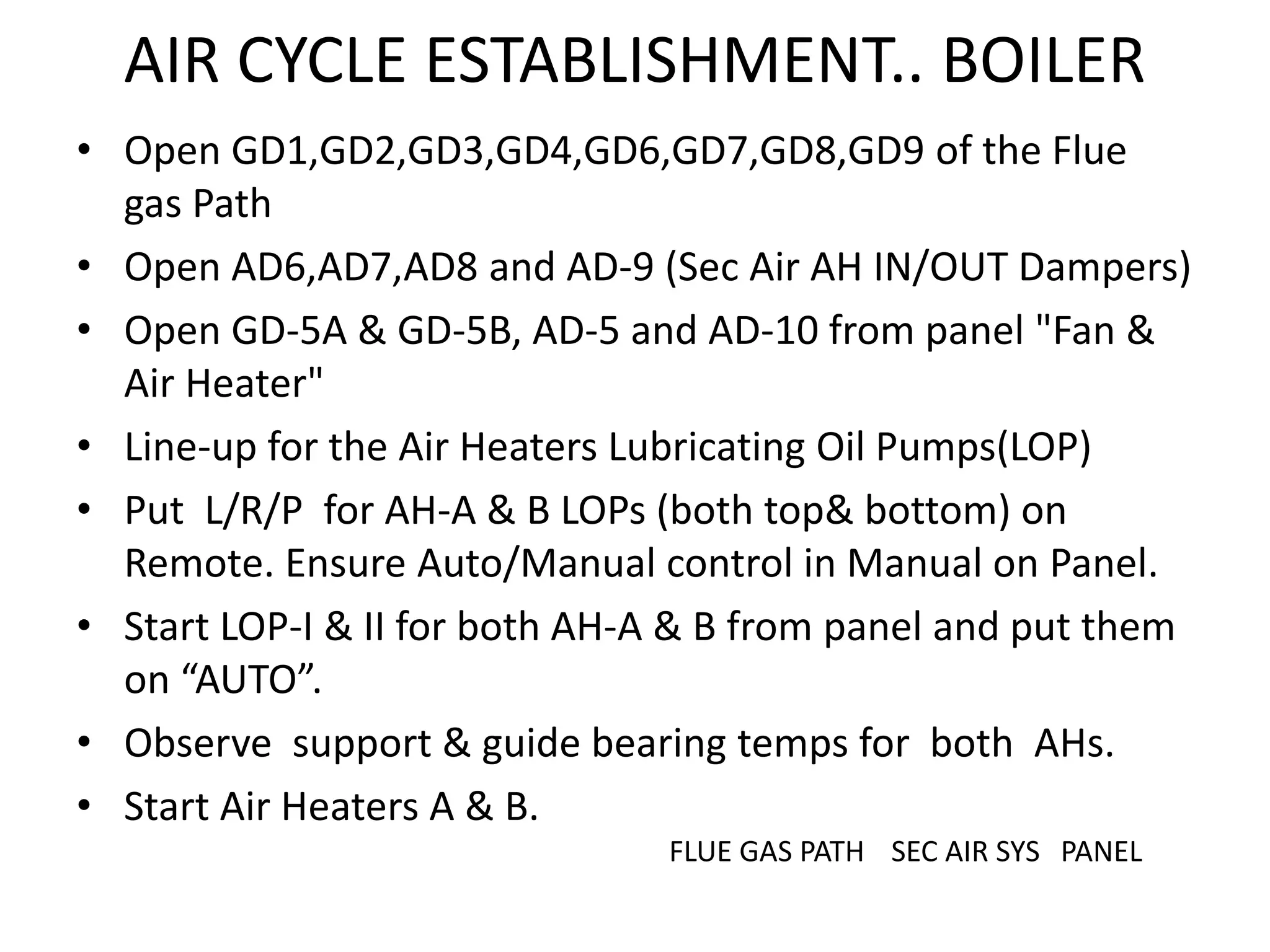


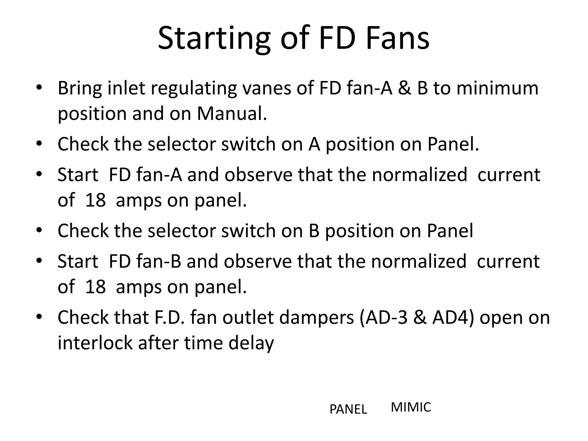


The document outlines the operational procedures for a thermal power plant simulator, emphasizing tasks related to the boiler and fan systems. Key steps include starting and monitoring various fans, adjusting dampers, and managing fuel supply for boiler ignition. Detailed instructions are provided for safety checks, process controls, and ensuring proper functionality of auxiliary systems during plant operations.


![Amardeep jadeja copy.ppt [autosaved]](https://cdn.slidesharecdn.com/ss_thumbnails/amardeepjadeja-copy-pptautosaved-111008011305-phpapp02-thumbnail.jpg?width=640&height=640&fit=bounds)