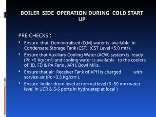
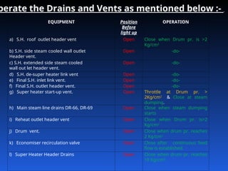
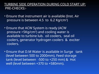
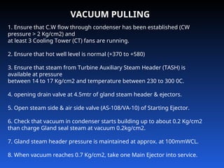
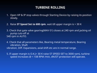
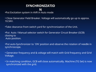
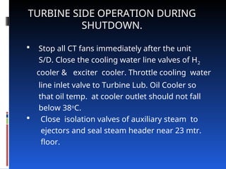
Cold , Hot start-up
& Shut-down
BOILER SIDE OPERATION DURING COLD START
UP
PRE CHECKS :
 Ensure that Demineralised (D.M) water is available in
Condensate Storage Tank (CST). (CST Level >5.0 mtr).
 Ensure that Auxiliary Cooling Water (ACW) system is ready
(Pr. >5 Kg/cm2
) and cooling water is available to the coolers
of ID, FD & PA Fans , APH, Bowl Mills.
 Ensure that air Receiver Tank of APH is charged with
service air (Pr. >3.5 Kg/cm2
).
 Ensure boiler drum level at normal level (0 -50 mm water
level in UCR & 5-6 ports in hydra-step at local )
Difference between cold, warm & hot start-up
If HP turbine casing temperature of turbine is below 150
D C before start-up than it is called cold start-up.
If HP casing temperature is in between 150 to 350 D C
than it is called warm start-up.
If HP casing temperature is above 350 D C than its called
HOT start-up.
Check the following:
• No foreign material is inside the boiler.
• All manholes, access doors & openings in the boiler
& ducts (Air & Gas side) are tightly closed.
• Furnace bottom ash hopper water sealing and seal
trough water sealing are OK.(Water flows
continuously in over flow lines)
• Burner tilt in horizontal position in all corners.
• The soot blowers are in retracted position.
• Check all the safety valves are in
non‑gagged position
• oil firing equipment checked and the LDO supply
system is ready up to Light Oil Trip Valve.
• check that cooling air to igniters and oil guns
is available. Drain the water from atomising air
line for oil guns & charge the air line.
• charge atomising steam line for HFO atomisation.
• steam tracing line of HFO is to be charged from
BASH and circulation of HFO is to be
established through Short Recirculation line (HO‑27
valve open).
• start scrapper conveyor and clinker grinder.
• keep the Steam Coil Air Pre-heaters (SCAPH) in
service with the steam from BASH.
EQUIPMENT Position
Before
light up
OPERATION
a) S.H. roof outlet header vent Open Close when Drum pr. is >2
Kg/cm2
b) S.H. side steam cooled wall outlet
Header vent.
Open ‑do‑
c) S.H. extended side steam cooled
wall out let header vent.
Open ‑do‑
d) S.H. de-super heater link vent Open ‑do‑
e) Final S.H. inlet link vent. Open ‑do‑
f) Final S.H. outlet header vent. Open ‑do‑
g) Super heater start‑up vent. Open Throttle at Drum pr. >
2Kg/cm2
& Close at steam
dumping.
h) Main steam line drains DR‑66, DR‑69 Open Close when steam dumping
starts
i) Reheat outlet header vent Open Close when Drum pr. is>2
Kg/cm2
j) Drum vent. Open Close when drum pr. reaches
2 Kg/cm2
k) Economiser recirculation valve Open Close after continuous feed
flow is established.
l) Super Heater Header Drains Open Close when drum pr. reaches
10 Kg/cm2
.
perate the Drains and Vents as mentioned below :-
ELECTROSTATIC PRECIPITATOR (ESP) OPERATION :
Prior to taking ESP in service, following steps are to be followed : ‑
• Switch ON all hopper heaters, shaft insulation heaters and
support insulation heaters about 24 hours prior to light up
of boiler. Check that all heaters are healthy & taking normal
rated current.
• Ensure that oil level in motor gear boxes of both emitting
and collecting rapping system is normal.
Also ensure that the direction of rotation of the rapping
motors is correct.
• Charge all the flushing apparatus with LP water and ensure
adequate whirling and flow through it.
• HP Water to jetting nozzles is to be charged.
• Start all the RV feeders of ESP
• Charge the ESP fields only after start of coal firing
and when the flue gas temperature at APH outlet
reaches 120o
C or above.
• Ensure opening of all the hopper plate valves
starting from the 1st field hoppers to the last field
after reaching a Boiler load of 30%.
• Ensure intermittent manual hammering of flushing
boxes to avoid hopper choking
TURBINE SIDE OPERATION DURING COLD START UP:
PRE-CHECKS:-
• Ensure that instrument air is available (Inst. Air
pressure is between 4.5 to 6.2 Kg/cm2
)
• Ensure that ACW System is ready (ACW
pressure >5Kg/cm2
) and cooling water is
available to turbine lub. oil coolers, seal oil
coolers, generator hydrogen coolers & exciter
coolers.
• Ensure that D.M Water is available in Surge tank
(level between 500 to 2000mm), Feed storage
tank (level between ‑500 to +250 mm) & Hot
well (level between +370 to +580mm).
• Ensure that gland water sealing lines of all the
valves under vacuum system are charged from
Surge tank.
• Ensure that oil level in Main Oil Tank (MOT) is
>95
cm (With no pumps running).
• Ensure that centrifuge is in service. Centrifuge
heater may be charged to maintain Tank oil
temp.
between 50o
C-65o
C.
• Ensure that M.O.T vapour extractor fan &
Generator
Bearing chamber exhaust fan are in service and
the dampers in individual line of turbine bearing
pedestals are open by about 40%.
• Seal oil pr. (> 4.5Kg/Cm2
at filter outlet) & H2
pressure (> 2.6 Kg/cm2
at gas rack) are O.K.
•Oil level in Seal Oil Tank (SOT) is visible in the
sight glass and Intermediate Oil Tank( IOT) level
is between 5 to 40 cm.
• Vacuum pump is running.(Vacuum in SOT
between 300 to 500 mmHg ).
• D.C (Emergency) Seal Oil Pump is put on Auto
Mode.
LIGHT-UP OF BOILER
1. Start both APH and one set of ID & FD fans.
2. Maintaining air flow in the Boiler between
170 to 200 t/hr. Maintain furnace draught at approx. -10 mmWC.
3. Charge Steam Coil Air Pre-heaters (SCAPH) from BASH.
4. Start A.C. Scanner Air Fan.
5. Purge the furnace with air flow of 170 to 200 TPH (Tons per Hour)
for 5 minutes.
6. Light-up the boiler with one pair of L.D.O. guns (AB Elevn.).
7. During bringing up pressure and temperature, the rise in
Saturation steam temperature
should not be more than 110 D C per hour.
8. HFO guns can be taken in to
service in other elevations as required when Boiler Drum pressure is
about 30 Kg/cm2 & /
or MS Temperature is about 310 DC).
.
DRAIN OPERATION & STEAM DUMPING :
For steam dumping following steps are to be taken;
1. Ensure that HP Bypass oil system is charged.
2. Open Main Steam strainer Drain valves DR‑74 & DR‑77.
3. Open Main steam line Drain valve DR‑263.
4. Open Main Stop Valve (MSV) seat Drain valves DR‑80 & DR‑83.
5. Ensure Hot Reheat (HRH) strainer Drains to (Flash Tank) FT‑2 i.e
DR‑104 & 99 are close.
6. Ensure IPSV (Intermediate Pressure Stop Valve) seat drains to FT‑2
i.e. DR‑109 & 114 are close.
7. Ensure Cold Reheat (CRH) drain to FT‑2 i.e. DR‑92 is close.
8. Open LP Bypass warm up line valves HR‑1 & HR‑4.
9. Open LP Bypass warm up drain line valves DR‑115 & DR‑117.
10. Open HRH strainer drains to DFT (Drain Flash Tank): DR‑ 101 &
DR‑96.
11. Open CRH drain to DFT: DR‑89.
12. Open drain before CRH Non Return Valves (NRVs):‑ MAL‑65 &
MAL‑66.
13. Open IPSV seat drain to DFT: DR‑106 & DR‑111.
VACUUM PULLING
1. Ensure that C.W flow through condenser has been established (CW
pressure > 2 Kg/cm2) and
at least 3 Cooling Tower (CT) fans are running.
2. Ensure that hot well level is normal (+370 to +580)
3. Ensure that steam from Turbine Auxiliary Steam Header (TASH) is
available at pressure
between 14 to 17 Kg/cm2 and temperature between 230 to 300 0C.
4. opening drain valve at 4.5mtr of gland steam header & ejectors.
5. Open steam side & air side valve (AS-108/VA-10) of Starting Ejector.
6. Check that vacuum in condenser starts building up to about 0.2 Kg/cm2
than charge Gland seal steam at vacuum 0.2kg/cm2.
7. Gland steam header pressure is maintained at approx. at 100mmWCL.
8. When vacuum reaches 0.7 Kg/cm2, take one Main Ejector into service.
TURBINE ROLLING
1. Open HP & IP stop valves through Starting Device by raising its position
slowly.
2. Raise ST Speed Set to 600 rpm. wait till upper margin is > 30 K
3. Check that gate valve gearing(MAV-51) closes at 240 rpm and jacking oil
pump cuts-off at
540 rpm in AUTO.
4. Check that all parameters like, Bearing metal temperature, Bearing
vibration, Shaft
vibration, Diff. Expansions, axial shift etc are in normal range.
5. If upper margin is O.K.(> 30 K raise ST SPEED SET to 3000 rpm), turbine
speed increases @ < 108 RPM /min, dN/DT protection will operate.
SYNCHRONIZATIO
N
•Put Excitation system in AVR in Auto mode
• Close Generator Field Breaker. Voltage will automatically go up to approx.
10.5KV.
•Take clearance from switch yard for synchronization of the Unit.
•Put Auto / Manual selector switch for Generator Circuit Breaker (GCB)
closing to
Auto position.
•Put auto-Synchronizer to `ON' position and observe the rotation of needle in
synchroscope.
• Generator frequency and & voltage will match with Grid frequency and Grid
Voltage.
• In matching condition, GCB will close automatically. Machine (TG Set) is now
synchronized with the grid.
 Stop all CT fans immediately after the unit
S/D. Close the cooling water line valves of H2
cooler & exciter cooler. Throttle cooling water
line inlet valve to Turbine Lub. Oil Cooler so
that oil temp. at cooler outlet should not fall
below 38o
C.
 Close isolation valves of auxiliary steam to
ejectors and seal steam header near 23 mtr.
floor.
TURBINE SIDE OPERATION DURING
SHUTDOWN.
Close the valve in valve gland sealing water
line from
Surge Tank near Surge Tank. Close the valve
in CEP
discharge line to chemical dozing tank.
• Stop the HP Bypass system oil pump by
pressing the
local Push Button of motor.
• Close DM‑8 and isolation valves of MC‑39,
MC‑41,
DM‑6.
• Open all drain line valves to Drain Flash Tank
(DFT).
BOLER SIDE OPERATION DURING
SHUTDOWN.
 Close MS‑ 3 , MS‑13 , MS‑1 & MS‑2 valves.
 Close Continuous Blow Down (CBD) valves at
firing Floor.
 Close all valves in Super heater & Re-heater
spray water lines.
 Isolate the HFO & LDO Station at firing floor.
Close the atomising steam line isolation valve.
 Close the atomising steam isolation valve &
SCAPH isolation valve from BASH at surge
tank floor.
• Open Super heater, Re-heater and Boiler drum vents
when Boiler Drum pressure reaches 2 Kg/cm2
.
Open Super heater Drains.
• Stop lub oil pumps of Fans and APHs etc. After
stopping of respective drives. Close the cooling water
line valves to the coolers of Fans, APHs & Coal Mills
after stopping the individual drives.
• Stop Clinker Grinder & Scrapper Conveyor when
Bottom Ash flow stops, preferably within 16 hrs of
Unit S/D.
• Switch off the ESP fields as soon as the last mill is
taken out of service.
• Put the emitting and collecting rapping motor in
continuous mode for about 30 minutes after switching
off the fields.
rapping system in ESP `ON' till clear water
comes
in flushing boxes & hoppers are emptied
completely or up to 16 hrs after Unit S/D.
Intermittently do hammering of the hoppers
and the flushing box.
• Close HP & LP water line main isolating valves
for
Ash system after ensuring that individual
hoppers
are empty, clear water is coming in flushing
boxes ,
the rapping system and heaters are made off
preferably within 16 hrs of unit S/D.
• During short S/D of the boiler, when the boiler
is hot
Thank you

Thermal power plants START UP AND SD.ppt

  • 1.
    Cold , Hotstart-up & Shut-down
  • 2.
    BOILER SIDE OPERATIONDURING COLD START UP PRE CHECKS :  Ensure that Demineralised (D.M) water is available in Condensate Storage Tank (CST). (CST Level >5.0 mtr).  Ensure that Auxiliary Cooling Water (ACW) system is ready (Pr. >5 Kg/cm2 ) and cooling water is available to the coolers of ID, FD & PA Fans , APH, Bowl Mills.  Ensure that air Receiver Tank of APH is charged with service air (Pr. >3.5 Kg/cm2 ).  Ensure boiler drum level at normal level (0 -50 mm water level in UCR & 5-6 ports in hydra-step at local )
  • 3.
    Difference between cold,warm & hot start-up If HP turbine casing temperature of turbine is below 150 D C before start-up than it is called cold start-up. If HP casing temperature is in between 150 to 350 D C than it is called warm start-up. If HP casing temperature is above 350 D C than its called HOT start-up.
  • 4.
    Check the following: •No foreign material is inside the boiler. • All manholes, access doors & openings in the boiler & ducts (Air & Gas side) are tightly closed. • Furnace bottom ash hopper water sealing and seal trough water sealing are OK.(Water flows continuously in over flow lines) • Burner tilt in horizontal position in all corners. • The soot blowers are in retracted position. • Check all the safety valves are in non‑gagged position
  • 5.
    • oil firingequipment checked and the LDO supply system is ready up to Light Oil Trip Valve. • check that cooling air to igniters and oil guns is available. Drain the water from atomising air line for oil guns & charge the air line. • charge atomising steam line for HFO atomisation. • steam tracing line of HFO is to be charged from BASH and circulation of HFO is to be established through Short Recirculation line (HO‑27 valve open). • start scrapper conveyor and clinker grinder. • keep the Steam Coil Air Pre-heaters (SCAPH) in service with the steam from BASH.
  • 6.
    EQUIPMENT Position Before light up OPERATION a)S.H. roof outlet header vent Open Close when Drum pr. is >2 Kg/cm2 b) S.H. side steam cooled wall outlet Header vent. Open ‑do‑ c) S.H. extended side steam cooled wall out let header vent. Open ‑do‑ d) S.H. de-super heater link vent Open ‑do‑ e) Final S.H. inlet link vent. Open ‑do‑ f) Final S.H. outlet header vent. Open ‑do‑ g) Super heater start‑up vent. Open Throttle at Drum pr. > 2Kg/cm2 & Close at steam dumping. h) Main steam line drains DR‑66, DR‑69 Open Close when steam dumping starts i) Reheat outlet header vent Open Close when Drum pr. is>2 Kg/cm2 j) Drum vent. Open Close when drum pr. reaches 2 Kg/cm2 k) Economiser recirculation valve Open Close after continuous feed flow is established. l) Super Heater Header Drains Open Close when drum pr. reaches 10 Kg/cm2 . perate the Drains and Vents as mentioned below :-
  • 7.
    ELECTROSTATIC PRECIPITATOR (ESP)OPERATION : Prior to taking ESP in service, following steps are to be followed : ‑ • Switch ON all hopper heaters, shaft insulation heaters and support insulation heaters about 24 hours prior to light up of boiler. Check that all heaters are healthy & taking normal rated current. • Ensure that oil level in motor gear boxes of both emitting and collecting rapping system is normal. Also ensure that the direction of rotation of the rapping motors is correct. • Charge all the flushing apparatus with LP water and ensure adequate whirling and flow through it. • HP Water to jetting nozzles is to be charged.
  • 8.
    • Start allthe RV feeders of ESP • Charge the ESP fields only after start of coal firing and when the flue gas temperature at APH outlet reaches 120o C or above. • Ensure opening of all the hopper plate valves starting from the 1st field hoppers to the last field after reaching a Boiler load of 30%. • Ensure intermittent manual hammering of flushing boxes to avoid hopper choking
  • 9.
    TURBINE SIDE OPERATIONDURING COLD START UP: PRE-CHECKS:- • Ensure that instrument air is available (Inst. Air pressure is between 4.5 to 6.2 Kg/cm2 ) • Ensure that ACW System is ready (ACW pressure >5Kg/cm2 ) and cooling water is available to turbine lub. oil coolers, seal oil coolers, generator hydrogen coolers & exciter coolers. • Ensure that D.M Water is available in Surge tank (level between 500 to 2000mm), Feed storage tank (level between ‑500 to +250 mm) & Hot well (level between +370 to +580mm).
  • 10.
    • Ensure thatgland water sealing lines of all the valves under vacuum system are charged from Surge tank. • Ensure that oil level in Main Oil Tank (MOT) is >95 cm (With no pumps running). • Ensure that centrifuge is in service. Centrifuge heater may be charged to maintain Tank oil temp. between 50o C-65o C. • Ensure that M.O.T vapour extractor fan & Generator Bearing chamber exhaust fan are in service and the dampers in individual line of turbine bearing pedestals are open by about 40%. • Seal oil pr. (> 4.5Kg/Cm2 at filter outlet) & H2 pressure (> 2.6 Kg/cm2 at gas rack) are O.K.
  • 11.
    •Oil level inSeal Oil Tank (SOT) is visible in the sight glass and Intermediate Oil Tank( IOT) level is between 5 to 40 cm. • Vacuum pump is running.(Vacuum in SOT between 300 to 500 mmHg ). • D.C (Emergency) Seal Oil Pump is put on Auto Mode.
  • 12.
    LIGHT-UP OF BOILER 1.Start both APH and one set of ID & FD fans. 2. Maintaining air flow in the Boiler between 170 to 200 t/hr. Maintain furnace draught at approx. -10 mmWC. 3. Charge Steam Coil Air Pre-heaters (SCAPH) from BASH. 4. Start A.C. Scanner Air Fan. 5. Purge the furnace with air flow of 170 to 200 TPH (Tons per Hour) for 5 minutes. 6. Light-up the boiler with one pair of L.D.O. guns (AB Elevn.). 7. During bringing up pressure and temperature, the rise in Saturation steam temperature should not be more than 110 D C per hour. 8. HFO guns can be taken in to service in other elevations as required when Boiler Drum pressure is about 30 Kg/cm2 & / or MS Temperature is about 310 DC).
  • 13.
    . DRAIN OPERATION &STEAM DUMPING : For steam dumping following steps are to be taken; 1. Ensure that HP Bypass oil system is charged. 2. Open Main Steam strainer Drain valves DR‑74 & DR‑77. 3. Open Main steam line Drain valve DR‑263. 4. Open Main Stop Valve (MSV) seat Drain valves DR‑80 & DR‑83. 5. Ensure Hot Reheat (HRH) strainer Drains to (Flash Tank) FT‑2 i.e DR‑104 & 99 are close. 6. Ensure IPSV (Intermediate Pressure Stop Valve) seat drains to FT‑2 i.e. DR‑109 & 114 are close. 7. Ensure Cold Reheat (CRH) drain to FT‑2 i.e. DR‑92 is close. 8. Open LP Bypass warm up line valves HR‑1 & HR‑4. 9. Open LP Bypass warm up drain line valves DR‑115 & DR‑117. 10. Open HRH strainer drains to DFT (Drain Flash Tank): DR‑ 101 & DR‑96. 11. Open CRH drain to DFT: DR‑89. 12. Open drain before CRH Non Return Valves (NRVs):‑ MAL‑65 & MAL‑66. 13. Open IPSV seat drain to DFT: DR‑106 & DR‑111.
  • 14.
    VACUUM PULLING 1. Ensurethat C.W flow through condenser has been established (CW pressure > 2 Kg/cm2) and at least 3 Cooling Tower (CT) fans are running. 2. Ensure that hot well level is normal (+370 to +580) 3. Ensure that steam from Turbine Auxiliary Steam Header (TASH) is available at pressure between 14 to 17 Kg/cm2 and temperature between 230 to 300 0C. 4. opening drain valve at 4.5mtr of gland steam header & ejectors. 5. Open steam side & air side valve (AS-108/VA-10) of Starting Ejector. 6. Check that vacuum in condenser starts building up to about 0.2 Kg/cm2 than charge Gland seal steam at vacuum 0.2kg/cm2. 7. Gland steam header pressure is maintained at approx. at 100mmWCL. 8. When vacuum reaches 0.7 Kg/cm2, take one Main Ejector into service.
  • 15.
    TURBINE ROLLING 1. OpenHP & IP stop valves through Starting Device by raising its position slowly. 2. Raise ST Speed Set to 600 rpm. wait till upper margin is > 30 K 3. Check that gate valve gearing(MAV-51) closes at 240 rpm and jacking oil pump cuts-off at 540 rpm in AUTO. 4. Check that all parameters like, Bearing metal temperature, Bearing vibration, Shaft vibration, Diff. Expansions, axial shift etc are in normal range. 5. If upper margin is O.K.(> 30 K raise ST SPEED SET to 3000 rpm), turbine speed increases @ < 108 RPM /min, dN/DT protection will operate.
  • 16.
    SYNCHRONIZATIO N •Put Excitation systemin AVR in Auto mode • Close Generator Field Breaker. Voltage will automatically go up to approx. 10.5KV. •Take clearance from switch yard for synchronization of the Unit. •Put Auto / Manual selector switch for Generator Circuit Breaker (GCB) closing to Auto position. •Put auto-Synchronizer to `ON' position and observe the rotation of needle in synchroscope. • Generator frequency and & voltage will match with Grid frequency and Grid Voltage. • In matching condition, GCB will close automatically. Machine (TG Set) is now synchronized with the grid.
  • 17.
     Stop allCT fans immediately after the unit S/D. Close the cooling water line valves of H2 cooler & exciter cooler. Throttle cooling water line inlet valve to Turbine Lub. Oil Cooler so that oil temp. at cooler outlet should not fall below 38o C.  Close isolation valves of auxiliary steam to ejectors and seal steam header near 23 mtr. floor. TURBINE SIDE OPERATION DURING SHUTDOWN.
  • 18.
    Close the valvein valve gland sealing water line from Surge Tank near Surge Tank. Close the valve in CEP discharge line to chemical dozing tank. • Stop the HP Bypass system oil pump by pressing the local Push Button of motor. • Close DM‑8 and isolation valves of MC‑39, MC‑41, DM‑6. • Open all drain line valves to Drain Flash Tank (DFT).
  • 19.
    BOLER SIDE OPERATIONDURING SHUTDOWN.  Close MS‑ 3 , MS‑13 , MS‑1 & MS‑2 valves.  Close Continuous Blow Down (CBD) valves at firing Floor.  Close all valves in Super heater & Re-heater spray water lines.  Isolate the HFO & LDO Station at firing floor. Close the atomising steam line isolation valve.  Close the atomising steam isolation valve & SCAPH isolation valve from BASH at surge tank floor.
  • 20.
    • Open Superheater, Re-heater and Boiler drum vents when Boiler Drum pressure reaches 2 Kg/cm2 . Open Super heater Drains. • Stop lub oil pumps of Fans and APHs etc. After stopping of respective drives. Close the cooling water line valves to the coolers of Fans, APHs & Coal Mills after stopping the individual drives. • Stop Clinker Grinder & Scrapper Conveyor when Bottom Ash flow stops, preferably within 16 hrs of Unit S/D. • Switch off the ESP fields as soon as the last mill is taken out of service. • Put the emitting and collecting rapping motor in continuous mode for about 30 minutes after switching off the fields.
  • 21.
    rapping system inESP `ON' till clear water comes in flushing boxes & hoppers are emptied completely or up to 16 hrs after Unit S/D. Intermittently do hammering of the hoppers and the flushing box. • Close HP & LP water line main isolating valves for Ash system after ensuring that individual hoppers are empty, clear water is coming in flushing boxes , the rapping system and heaters are made off preferably within 16 hrs of unit S/D. • During short S/D of the boiler, when the boiler is hot
  • 23.