Downloaded 136 times


![Introduction
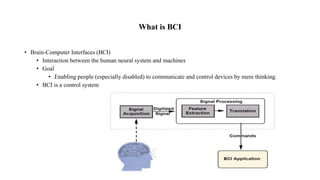
• It is the study of brain functions.
• A collaboration in which a brain accepts and controls a mechanical device.
• Direct communication pathway between a brain and an external device.
• Thus BCI extracts electro-physical signals from suitable components of the brain and process
them to generate control signals for computers, robotic machines or communication devices.
“ A Brain-Computer Interface is a communication system that do not depend on peripheral nerves
and muscles “
[J. R. Wolpaw et al. “Brain-computer interface technology: A review of the first international
meeting,” IEEE Trans. Rehab. Eng., vol. 8, no. 2, pp. 164–173, 2000]](https://image.slidesharecdn.com/brainwavecontrolledrobot-151105062603-lva1-app6891/85/Brain-wave-controlled-robot-3-320.jpg)


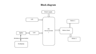


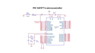


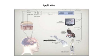

This document describes a brain-computer interface system to control an electric wheelchair. It discusses using EEG signals detected from the forehead to control the wheelchair's movement wirelessly through a Zigbee module. The system uses a PIC16F877A microcontroller for processing the EEG signals and controlling the motor driver and wireless transmission. It provides advantages of enabling disabled patients to control a wheelchair through thought but has disadvantages of the brain being complex and signals being weak and prone to interference. Potential applications are to help improve mobility for people with limited motor function.