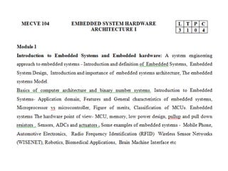
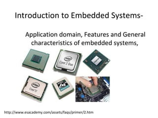
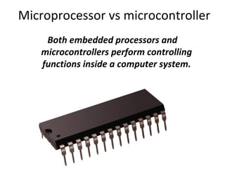
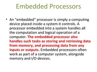
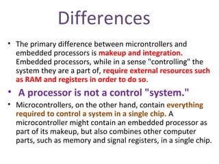
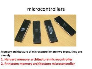
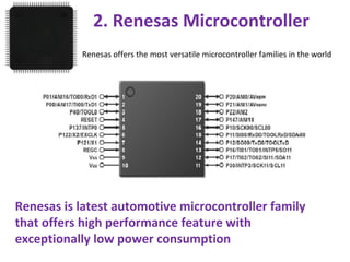
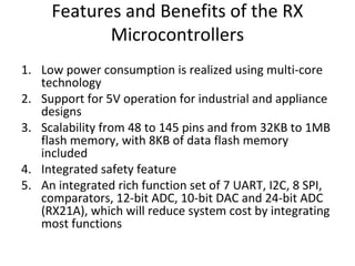
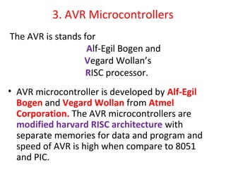
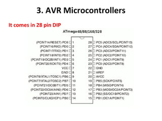
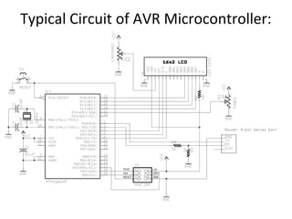
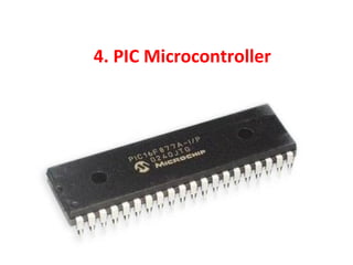
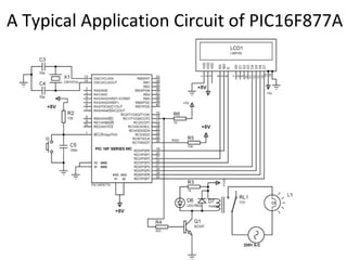
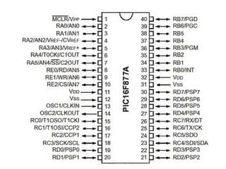
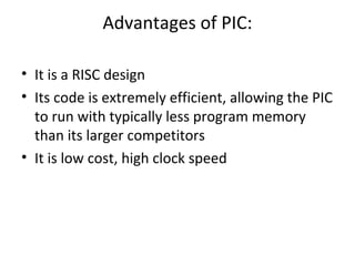
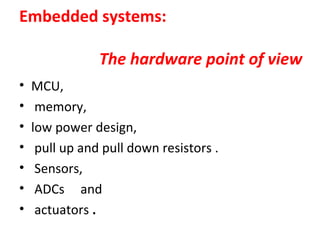
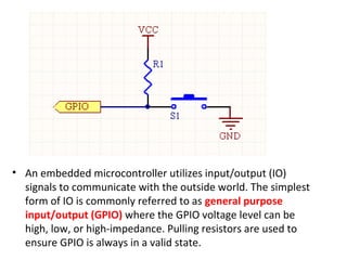
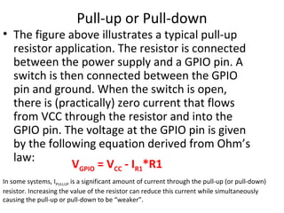
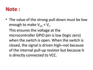
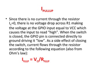
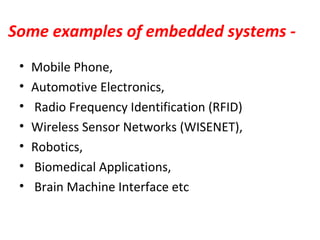
MECVE 104
EMBEDDED SYSTEM HARDWARE
ARCHITECTURE I
By
AJAL.A.J
AP/ ECE DEPARTMENT
MAIL: ec2reach@gmail.com
Mob: 8907305642
Basics of computer architecture and
binary number systems.
Introduction to Embedded Systems-
Application domain, Features and General
characteristics of embedded systems,
http://www.esacademy.com/assets/faqs/primer/2.htm
Microprocessor vs microcontroller
Both embedded processors and
microcontrollers perform controlling
functions inside a computer system.
The Difference Between an Embedded
Processor & a Microcontroller
• Controllers
Controllers are special pieces of digital
equipment that control some aspect of their
environment, according to responses from that
environment. Typical types of controllers include
those for home temperature regulation systems
or security systems. A controller can be thought
of as a self-contained computer that controls
another system. Often, older controllers were
large pieces of machinery contained externally
from the system they controlled.
Microcontrollers
• As computer miniaturization progressed through the
mid to late 1900s, controllers became smaller and
smaller. All the parts of a controller, including memory
and I/O devices, became integrated with the controller
as a standard. Finally, when the entire controller
apparatus was able to fit on single chips, they became
known as "microcontrollers." A microcontroller
contains everything required to control an external
system, and nothing else. This limiting of
microcontroller functionality to the basic requirements
of a control unit makes implementing microcontrollers
cheap and easy.
Embedded Processors
• An "embedded" processor is simply a computing
device placed inside a system it controls. A
processor embedded into a system handles all
the computation and logical operation of a
computer. The embedded processor also
handles such tasks as storing and retrieving data
from memory, and processing data from any
inputs or outputs. Embedded processors often
work as part of a computer system, alongside
memory and I/O devices.
Differences
• The primary difference between microntrollers and
embedded processors is makeup and integration.
Embedded processors, while in a sense "controlling" the
system they are a part of, require external resources such
as RAM and registers in order to do so.
• A processor is not a control "system."
• Microcontrollers, on the other hand, contain everything
required to control a system in a single chip. A
microcontroller might contain an embedded processor as
part of its makeup, but also combines other computer
parts, such as memory and signal registers, in a single chip.
microcontrollers
Memory architecture of microcontroller are two types, they are
namely:
1. Harvard memory architecture microcontroller
2. Princeton memory architecture microcontroller
1. Harvard Memory Architecture
Microcontroller:
• The point when a microcontroller unit has a
dissimilar memory address space for the
program and data memory, the microcontroller
has Harvard memory architecture in the
processor.
2. Princeton Memory Architecture
Microcontroller:
• The point when a microcontroller has a
common memory address for the program
memory and data memory, the
microcontroller has Princeton memory
architecture in the processor.
Classification of MCUs.
4 Types of Microcontrollers
1.Microcontroller 8051
2.Renesas Microcontroller
3.AVR Microcontrollers
4.PIC Microcontroller
1. Microcontroller
8051
2. Renesas Microcontroller
Renesas offers the most versatile microcontroller families in the world
Renesas is latest automotive microcontroller family
that offers high performance feature with
exceptionally low power consumption
Features and Benefits of the RX
Microcontrollers
1. Low power consumption is realized using multi-core
technology
2. Support for 5V operation for industrial and appliance
designs
3. Scalability from 48 to 145 pins and from 32KB to 1MB
flash memory, with 8KB of data flash memory
included
4. Integrated safety feature
5. An integrated rich function set of 7 UART, I2C, 8 SPI,
comparators, 12-bit ADC, 10-bit DAC and 24-bit ADC
(RX21A), which will reduce system cost by integrating
most functions
Application of Renesas Microcontroller:
1. Industrial automation
2. Communication applications
3. Motor control applications
4. Test and measurement
5. Medical applications
3. AVR Microcontrollers
• AVR microcontroller is developed by Alf-Egil
Bogen and Vegard Wollan from Atmel
Corporation. The AVR microcontrollers are
modified harvard RISC architecture with
separate memories for data and program and
speed of AVR is high when compare to 8051
and PIC.
The AVR is stands for
Alf-Egil Bogen and
Vegard Wollan’s
RISC processor.
3. AVR Microcontrollers
It comes in 28 pin DIP
Features of AVR Microcontroller:
1. 16KB of In-System Programmable Flash
2. 512B of In-System Programmable EEPROM
3. 16-bit Timer with extra features
4. Multiple internal oscillators
5. Internal, self-programmable instruction flash memory up to 256K
6. In-system programmable using ISP, JTAG or high voltage methods
7. Optional boot code section with independent lock bits for protection
8. Synchronous/asynchronous serial peripherals (UART/USART)
9. Serial peripheral interface bus (SPI)
10. Universal serial interface (USI) for two/three-wire synchronous data transfer
11. Watchdog timer (WDT)
12. Multiple power-saving sleep modes
13. 10-bit A/D Converters, with multiplex of up to 16 channels
14. CAN and USB controller support
15. Low-voltage devices operating down to 1.8v
Difference between 8051 and AVR
Controllers:
1. 8051s are 8-bit controllers based on CISC
architecture, AVRs are 8-bit controllers based
on RISC architecture
2. 8051 consumes more power than AVR
microcontroller
3. In 8051, we can program easily than the AVR
microcontroller
4. The speed of AVR is more than the 8051
microcontroller
Classification of AVR Controllers:
AVR Microcontrollers are classified into three types:
• TinyAVR – Less memory, small size, suitable only for
simpler applications
• MegaAVR – These are the most popular ones having
good amount of memory (up to 256 KB), higher
number of inbuilt peripherals and suitable for
moderate to complex applications
• XmegaAVR – Used commercially for complex
applications, which require large program memory
and high speed
Features of ATmega328:
1. 28-pin AVR microcontroller
2. Flash program memory of 32kbytes
3. EEPROM data memory of 1kbytes
4. SRAM data memory of 2kbytes
5. I/O pins are 23
6. Two 8-bit timers
7. A/D converter
8. Six channel PWM
9. In built USART
10. External Oscillator: up to 20MHz
Typical Circuit of AVR Microcontroller:
Applications of AVR Microcontroller:
• There are many applications of AVR
microcontroller; they are used in home
automation, touch screen, automobiles,
medical devices and defense.
4. PIC Microcontroller
A Typical Application Circuit of PIC16F877A
Advantages of PIC:
• It is a RISC design
• Its code is extremely efficient, allowing the PIC
to run with typically less program memory
than its larger competitors
• It is low cost, high clock speed
CISC vs RISC
Classification According to Instruction Set
CISC vs RISC
• CISC: CISC is a Complex Instruction Set Computer.
It allows the programmer to use one instruction
in place of many simpler instructions.
• RISC: The RISC is stands for Reduced Instruction
set Computer, this type of instruction sets
reduces the design of microprocessor for industry
standards. It allows each instruction to operate
on any register or use any addressing mode and
simultaneous access of program and data.
Figure of merits
A figure of merit is a quantity used to
characterize the performance of a
device, system or method, relative to its
alternatives. In engineering, figures of
merit are used as a marketing tool to
convince consumers to choose a
particular brand.
a numerical quantity based on one or more characteristics of a system or device that represents
a measure of efficiency or effectiveness. A FOM may be either a qualitative or quantitative
measure, depending on the accuracy and integrity of the data used to calculate the FOM.
@ Modulation Systems
• In modulation systems for communication,
figure of merit of a device means the ratio of
output Signal to Noise Ratio to the input
Signal to Noise Ratio.
@ Amplitude modulation
• Figure of merit for Amplitude modulation is
given by
• Figure of merit for DSB-SC receiver or that of
an SSB modulation is always unity. Therefore
noise performance of AM receiver is inferior
to that of a DSB-SC receiver or an SSB
receiver.
@ Frequency modulation
• Figure of merit for Frequency modulation
is given by
Embedded systems:
The hardware point of view
• MCU,
• memory,
• low power design,
• pull up and pull down resistors .
• Sensors,
• ADCs and
• actuators .
Pull up and Pull down resistors
• Pull-up/pull-down resistors are a great way to
prevent microcontroller GPIO inputs from
assuming undefined values in embedded
designs; however, they must be correctly
sized (either weak or strong) based on power
consumption requirements as well as existing
circuitry (such as internal pull-up/pull-down
resistors) to ensure proper circuit operation.
Using Pull-Up and Pull-Down
Resistors@ Embedded Design
pull-up/down resistors can be used on both input and output pins, depending
on application
• An embedded microcontroller utilizes input/output (IO)
signals to communicate with the outside world. The simplest
form of IO is commonly referred to as general purpose
input/output (GPIO) where the GPIO voltage level can be
high, low, or high-impedance. Pulling resistors are used to
ensure GPIO is always in a valid state.
GPIO Input States on an Embedded
Microcontroller
• GPIO on a microcontroller is usually configured as
either input or output. As an input, the pin can take
one of three states: low, high, and floating (also called
high-impedance or tri-stated). When an input is driven
above the input high threshold, it is high (or logic one).
When driven below the input low threshold, the input
is low (or logic zero). When in a high-impedance state,
the input level is not reliably high nor low. To ensure
an input value is always in a known state, a pull-up or
pull-down resistor is used. A pull-up resistor pulls the
signal to a high state unless it is driven low while a
pull-down resistor puts the signal in a low state unless
driven high.
Pull-up or Pull-down
• The figure above illustrates a typical pull-up
resistor application. The resistor is connected
between the power supply and a GPIO pin. A
switch is then connected between the GPIO
pin and ground. When the switch is open,
there is (practically) zero current that flows
from VCC through the resistor and into the
GPIO pin. The voltage at the GPIO pin is given
by the following equation derived from Ohm’s
law:
VGPIO = VCC - IR1*R1
In some systems, IPULLUP is a significant amount of current through the pull-up (or pull-down)
resistor. Increasing the value of the resistor can reduce this current while simultaneously
causing the pull-up or pull-down to be “weaker”.
Weak or Strong Pull-up/Pull-down
Resistor
• A weak pull-up/pull-down resistor typically has a
value of tens or hundreds of kilo-ohms. Strong
pulling resistors have values of a few kilo-ohms
and can override weak pulling resistors if both
are used on the same microcontroller GPIO pin.
The circuit below shows a GPIO pin with a weak
internal pull-up resistor–most modern
microcontroller designs have built-in pull-up
and/or pull-down resistors on each GPIO pin–and
a strong external pull-down resistor.
Weak or Strong Pull-up/Pull-down
Resistor
• In order for the strong pull-down resistor to
work properly, it must be correctly sized.
During normal operation, the voltage at the
GPIO pin must be below the input low voltage
VIL as specified in the electrical characteristics
section of the device’s datasheet. The voltage
at the GPIO pin is calculated using a voltage
divider:
VGPIO = VCC * R1 / (R2 + R1)
Note :
• The value of the strong pull-down must be low
enough to make VGPIO < VIL.
This ensures the voltage at the
microcontroller GPIO pin is low (logic zero)
when the switch is open. When the switch is
closed, the signal is driven high–not because
of the internal pull-up resistor but because it
is directly connected to VCC.
IPULLUP
• Since there is no current through the resistor
IR1=0, there is no voltage drop across R1 making
the voltage at the GPIO input equal to VCC which
causes the input to read “high”. When the switch
is closed, the GPIO pin is connected directly to
ground driving it “low”. As a side effect of closing
the switch, current flows through the resistor
according to the following equation (also from
Ohm’s law):
IPULLUP = VCC/RPULLUP
Some examples of embedded systems -
• Mobile Phone,
• Automotive Electronics,
• Radio Frequency Identification (RFID)
• Wireless Sensor Networks (WISENET),
• Robotics,
• Biomedical Applications,
• Brain Machine Interface etc

Ajal mod 1

  • 1.
    MECVE 104 EMBEDDED SYSTEMHARDWARE ARCHITECTURE I By AJAL.A.J AP/ ECE DEPARTMENT MAIL: ec2reach@gmail.com Mob: 8907305642
  • 3.
    Basics of computerarchitecture and binary number systems.
  • 4.
    Introduction to EmbeddedSystems- Application domain, Features and General characteristics of embedded systems, http://www.esacademy.com/assets/faqs/primer/2.htm
  • 5.
    Microprocessor vs microcontroller Bothembedded processors and microcontrollers perform controlling functions inside a computer system.
  • 6.
    The Difference Betweenan Embedded Processor & a Microcontroller • Controllers Controllers are special pieces of digital equipment that control some aspect of their environment, according to responses from that environment. Typical types of controllers include those for home temperature regulation systems or security systems. A controller can be thought of as a self-contained computer that controls another system. Often, older controllers were large pieces of machinery contained externally from the system they controlled.
  • 7.
    Microcontrollers • As computerminiaturization progressed through the mid to late 1900s, controllers became smaller and smaller. All the parts of a controller, including memory and I/O devices, became integrated with the controller as a standard. Finally, when the entire controller apparatus was able to fit on single chips, they became known as "microcontrollers." A microcontroller contains everything required to control an external system, and nothing else. This limiting of microcontroller functionality to the basic requirements of a control unit makes implementing microcontrollers cheap and easy.
  • 8.
    Embedded Processors • An"embedded" processor is simply a computing device placed inside a system it controls. A processor embedded into a system handles all the computation and logical operation of a computer. The embedded processor also handles such tasks as storing and retrieving data from memory, and processing data from any inputs or outputs. Embedded processors often work as part of a computer system, alongside memory and I/O devices.
  • 9.
    Differences • The primarydifference between microntrollers and embedded processors is makeup and integration. Embedded processors, while in a sense "controlling" the system they are a part of, require external resources such as RAM and registers in order to do so. • A processor is not a control "system." • Microcontrollers, on the other hand, contain everything required to control a system in a single chip. A microcontroller might contain an embedded processor as part of its makeup, but also combines other computer parts, such as memory and signal registers, in a single chip.
  • 11.
    microcontrollers Memory architecture ofmicrocontroller are two types, they are namely: 1. Harvard memory architecture microcontroller 2. Princeton memory architecture microcontroller
  • 12.
    1. Harvard MemoryArchitecture Microcontroller: • The point when a microcontroller unit has a dissimilar memory address space for the program and data memory, the microcontroller has Harvard memory architecture in the processor.
  • 13.
    2. Princeton MemoryArchitecture Microcontroller: • The point when a microcontroller has a common memory address for the program memory and data memory, the microcontroller has Princeton memory architecture in the processor.
  • 14.
  • 15.
    4 Types ofMicrocontrollers 1.Microcontroller 8051 2.Renesas Microcontroller 3.AVR Microcontrollers 4.PIC Microcontroller
  • 16.
  • 17.
    2. Renesas Microcontroller Renesasoffers the most versatile microcontroller families in the world Renesas is latest automotive microcontroller family that offers high performance feature with exceptionally low power consumption
  • 18.
    Features and Benefitsof the RX Microcontrollers 1. Low power consumption is realized using multi-core technology 2. Support for 5V operation for industrial and appliance designs 3. Scalability from 48 to 145 pins and from 32KB to 1MB flash memory, with 8KB of data flash memory included 4. Integrated safety feature 5. An integrated rich function set of 7 UART, I2C, 8 SPI, comparators, 12-bit ADC, 10-bit DAC and 24-bit ADC (RX21A), which will reduce system cost by integrating most functions
  • 19.
    Application of RenesasMicrocontroller: 1. Industrial automation 2. Communication applications 3. Motor control applications 4. Test and measurement 5. Medical applications
  • 20.
    3. AVR Microcontrollers •AVR microcontroller is developed by Alf-Egil Bogen and Vegard Wollan from Atmel Corporation. The AVR microcontrollers are modified harvard RISC architecture with separate memories for data and program and speed of AVR is high when compare to 8051 and PIC. The AVR is stands for Alf-Egil Bogen and Vegard Wollan’s RISC processor.
  • 21.
    3. AVR Microcontrollers Itcomes in 28 pin DIP
  • 22.
    Features of AVRMicrocontroller: 1. 16KB of In-System Programmable Flash 2. 512B of In-System Programmable EEPROM 3. 16-bit Timer with extra features 4. Multiple internal oscillators 5. Internal, self-programmable instruction flash memory up to 256K 6. In-system programmable using ISP, JTAG or high voltage methods 7. Optional boot code section with independent lock bits for protection 8. Synchronous/asynchronous serial peripherals (UART/USART) 9. Serial peripheral interface bus (SPI) 10. Universal serial interface (USI) for two/three-wire synchronous data transfer 11. Watchdog timer (WDT) 12. Multiple power-saving sleep modes 13. 10-bit A/D Converters, with multiplex of up to 16 channels 14. CAN and USB controller support 15. Low-voltage devices operating down to 1.8v
  • 23.
    Difference between 8051and AVR Controllers: 1. 8051s are 8-bit controllers based on CISC architecture, AVRs are 8-bit controllers based on RISC architecture 2. 8051 consumes more power than AVR microcontroller 3. In 8051, we can program easily than the AVR microcontroller 4. The speed of AVR is more than the 8051 microcontroller
  • 24.
    Classification of AVRControllers: AVR Microcontrollers are classified into three types: • TinyAVR – Less memory, small size, suitable only for simpler applications • MegaAVR – These are the most popular ones having good amount of memory (up to 256 KB), higher number of inbuilt peripherals and suitable for moderate to complex applications • XmegaAVR – Used commercially for complex applications, which require large program memory and high speed
  • 25.
    Features of ATmega328: 1.28-pin AVR microcontroller 2. Flash program memory of 32kbytes 3. EEPROM data memory of 1kbytes 4. SRAM data memory of 2kbytes 5. I/O pins are 23 6. Two 8-bit timers 7. A/D converter 8. Six channel PWM 9. In built USART 10. External Oscillator: up to 20MHz
  • 26.
    Typical Circuit ofAVR Microcontroller:
  • 27.
    Applications of AVRMicrocontroller: • There are many applications of AVR microcontroller; they are used in home automation, touch screen, automobiles, medical devices and defense.
  • 28.
  • 29.
    A Typical ApplicationCircuit of PIC16F877A
  • 31.
    Advantages of PIC: •It is a RISC design • Its code is extremely efficient, allowing the PIC to run with typically less program memory than its larger competitors • It is low cost, high clock speed
  • 32.
    CISC vs RISC ClassificationAccording to Instruction Set
  • 33.
    CISC vs RISC •CISC: CISC is a Complex Instruction Set Computer. It allows the programmer to use one instruction in place of many simpler instructions. • RISC: The RISC is stands for Reduced Instruction set Computer, this type of instruction sets reduces the design of microprocessor for industry standards. It allows each instruction to operate on any register or use any addressing mode and simultaneous access of program and data.
  • 34.
    Figure of merits Afigure of merit is a quantity used to characterize the performance of a device, system or method, relative to its alternatives. In engineering, figures of merit are used as a marketing tool to convince consumers to choose a particular brand. a numerical quantity based on one or more characteristics of a system or device that represents a measure of efficiency or effectiveness. A FOM may be either a qualitative or quantitative measure, depending on the accuracy and integrity of the data used to calculate the FOM.
  • 35.
    @ Modulation Systems •In modulation systems for communication, figure of merit of a device means the ratio of output Signal to Noise Ratio to the input Signal to Noise Ratio.
  • 36.
    @ Amplitude modulation •Figure of merit for Amplitude modulation is given by • Figure of merit for DSB-SC receiver or that of an SSB modulation is always unity. Therefore noise performance of AM receiver is inferior to that of a DSB-SC receiver or an SSB receiver.
  • 37.
    @ Frequency modulation •Figure of merit for Frequency modulation is given by
  • 38.
    Embedded systems: The hardwarepoint of view • MCU, • memory, • low power design, • pull up and pull down resistors . • Sensors, • ADCs and • actuators .
  • 39.
    Pull up andPull down resistors • Pull-up/pull-down resistors are a great way to prevent microcontroller GPIO inputs from assuming undefined values in embedded designs; however, they must be correctly sized (either weak or strong) based on power consumption requirements as well as existing circuitry (such as internal pull-up/pull-down resistors) to ensure proper circuit operation.
  • 40.
    Using Pull-Up andPull-Down Resistors@ Embedded Design pull-up/down resistors can be used on both input and output pins, depending on application
  • 41.
    • An embeddedmicrocontroller utilizes input/output (IO) signals to communicate with the outside world. The simplest form of IO is commonly referred to as general purpose input/output (GPIO) where the GPIO voltage level can be high, low, or high-impedance. Pulling resistors are used to ensure GPIO is always in a valid state.
  • 42.
    GPIO Input Stateson an Embedded Microcontroller • GPIO on a microcontroller is usually configured as either input or output. As an input, the pin can take one of three states: low, high, and floating (also called high-impedance or tri-stated). When an input is driven above the input high threshold, it is high (or logic one). When driven below the input low threshold, the input is low (or logic zero). When in a high-impedance state, the input level is not reliably high nor low. To ensure an input value is always in a known state, a pull-up or pull-down resistor is used. A pull-up resistor pulls the signal to a high state unless it is driven low while a pull-down resistor puts the signal in a low state unless driven high.
  • 43.
    Pull-up or Pull-down •The figure above illustrates a typical pull-up resistor application. The resistor is connected between the power supply and a GPIO pin. A switch is then connected between the GPIO pin and ground. When the switch is open, there is (practically) zero current that flows from VCC through the resistor and into the GPIO pin. The voltage at the GPIO pin is given by the following equation derived from Ohm’s law: VGPIO = VCC - IR1*R1 In some systems, IPULLUP is a significant amount of current through the pull-up (or pull-down) resistor. Increasing the value of the resistor can reduce this current while simultaneously causing the pull-up or pull-down to be “weaker”.
  • 44.
    Weak or StrongPull-up/Pull-down Resistor • A weak pull-up/pull-down resistor typically has a value of tens or hundreds of kilo-ohms. Strong pulling resistors have values of a few kilo-ohms and can override weak pulling resistors if both are used on the same microcontroller GPIO pin. The circuit below shows a GPIO pin with a weak internal pull-up resistor–most modern microcontroller designs have built-in pull-up and/or pull-down resistors on each GPIO pin–and a strong external pull-down resistor.
  • 45.
    Weak or StrongPull-up/Pull-down Resistor
  • 46.
    • In orderfor the strong pull-down resistor to work properly, it must be correctly sized. During normal operation, the voltage at the GPIO pin must be below the input low voltage VIL as specified in the electrical characteristics section of the device’s datasheet. The voltage at the GPIO pin is calculated using a voltage divider: VGPIO = VCC * R1 / (R2 + R1)
  • 47.
    Note : • Thevalue of the strong pull-down must be low enough to make VGPIO < VIL. This ensures the voltage at the microcontroller GPIO pin is low (logic zero) when the switch is open. When the switch is closed, the signal is driven high–not because of the internal pull-up resistor but because it is directly connected to VCC.
  • 48.
    IPULLUP • Since thereis no current through the resistor IR1=0, there is no voltage drop across R1 making the voltage at the GPIO input equal to VCC which causes the input to read “high”. When the switch is closed, the GPIO pin is connected directly to ground driving it “low”. As a side effect of closing the switch, current flows through the resistor according to the following equation (also from Ohm’s law): IPULLUP = VCC/RPULLUP
  • 49.
    Some examples ofembedded systems - • Mobile Phone, • Automotive Electronics, • Radio Frequency Identification (RFID) • Wireless Sensor Networks (WISENET), • Robotics, • Biomedical Applications, • Brain Machine Interface etc