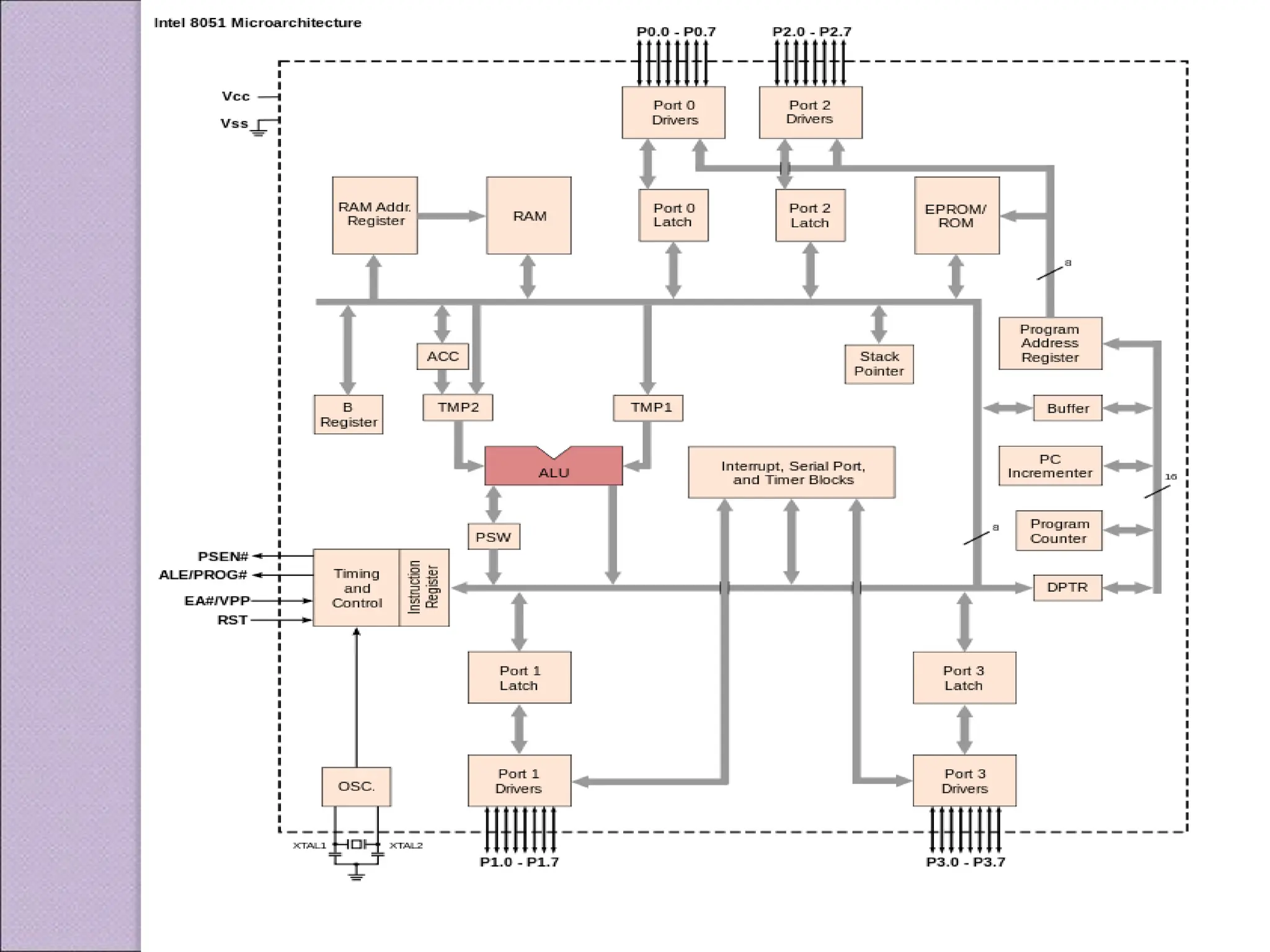
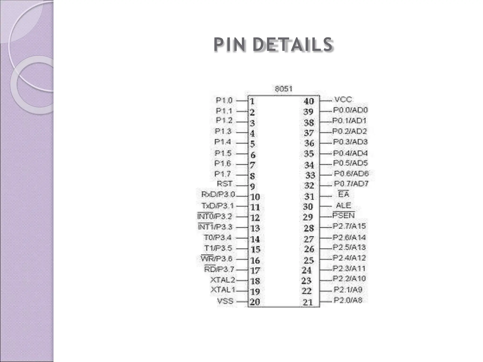
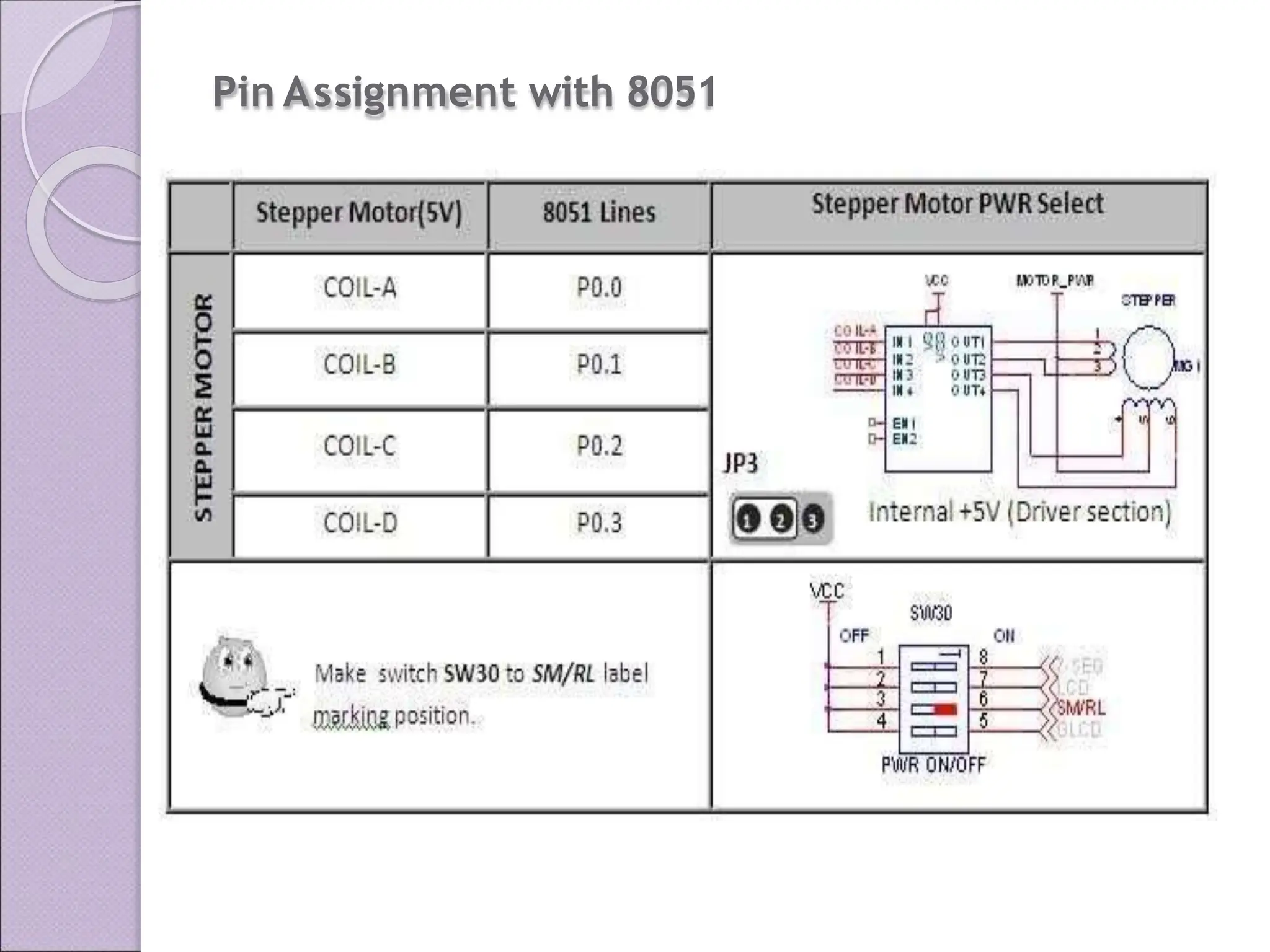
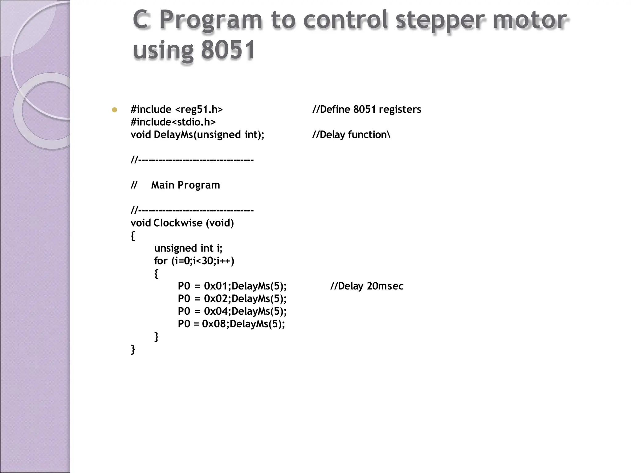
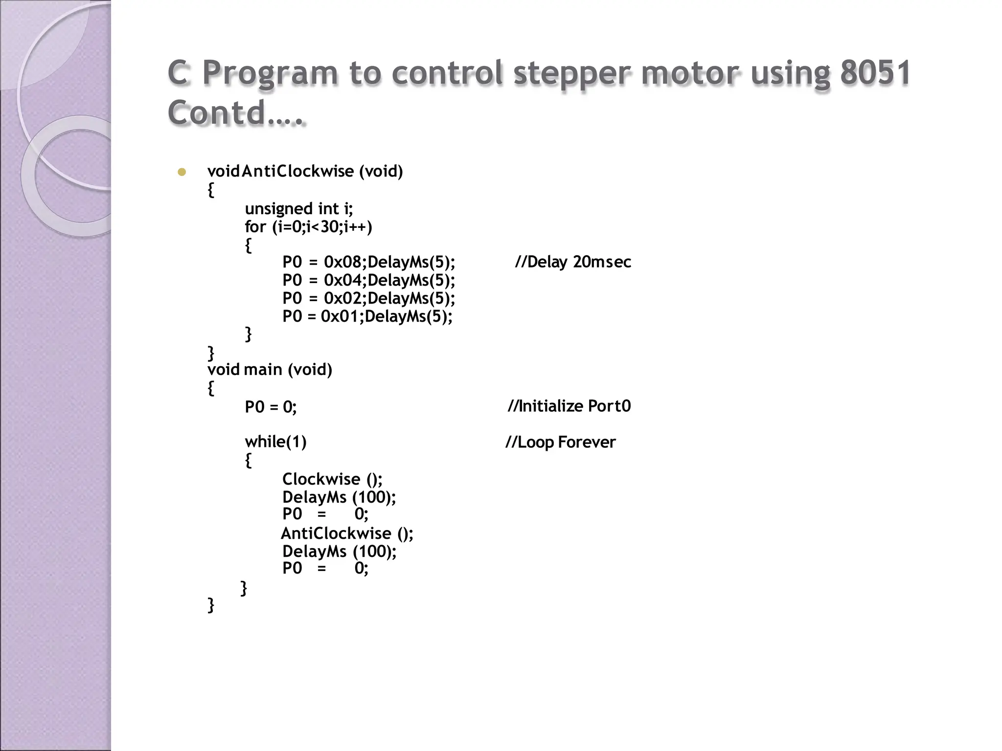
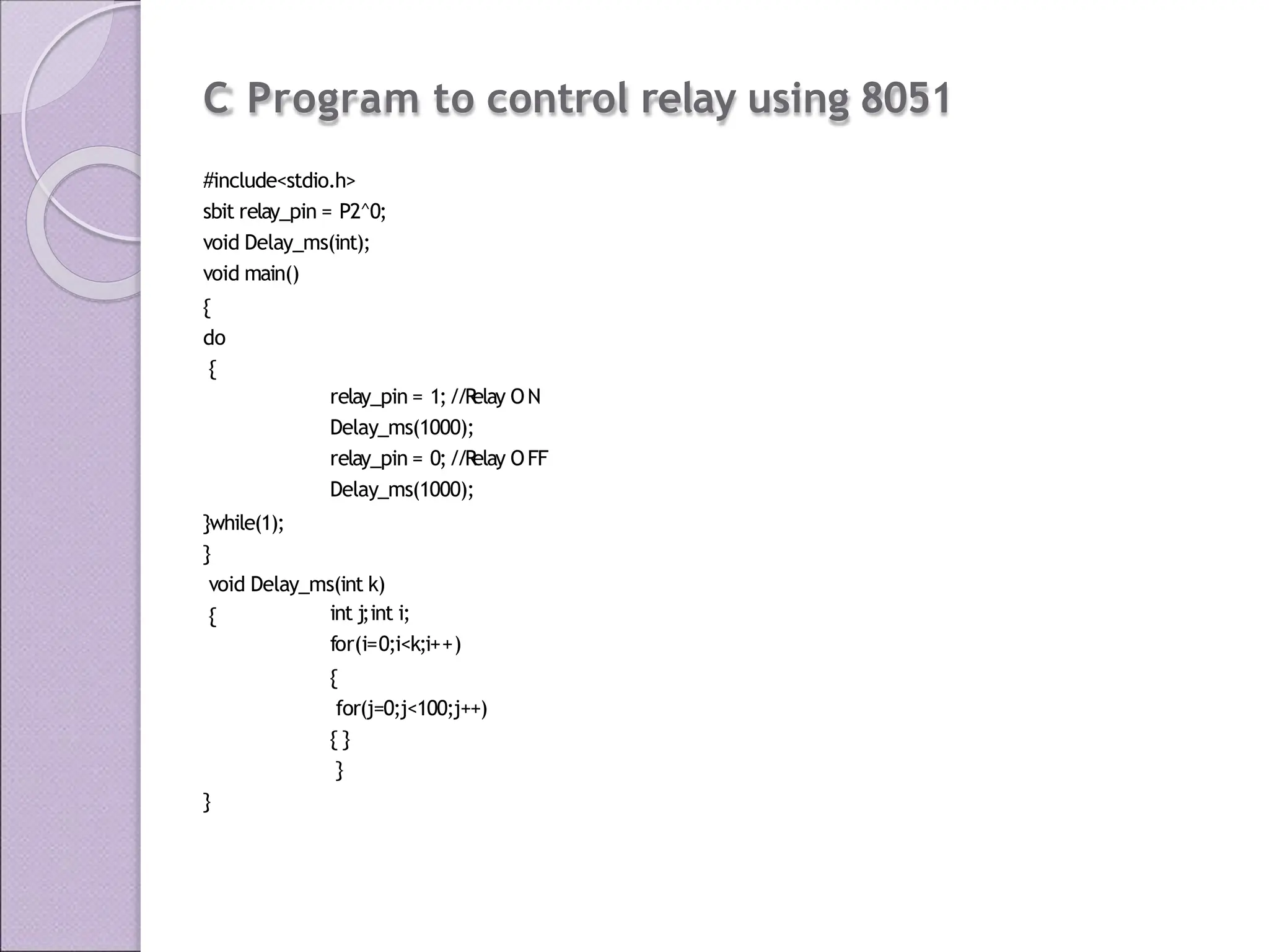
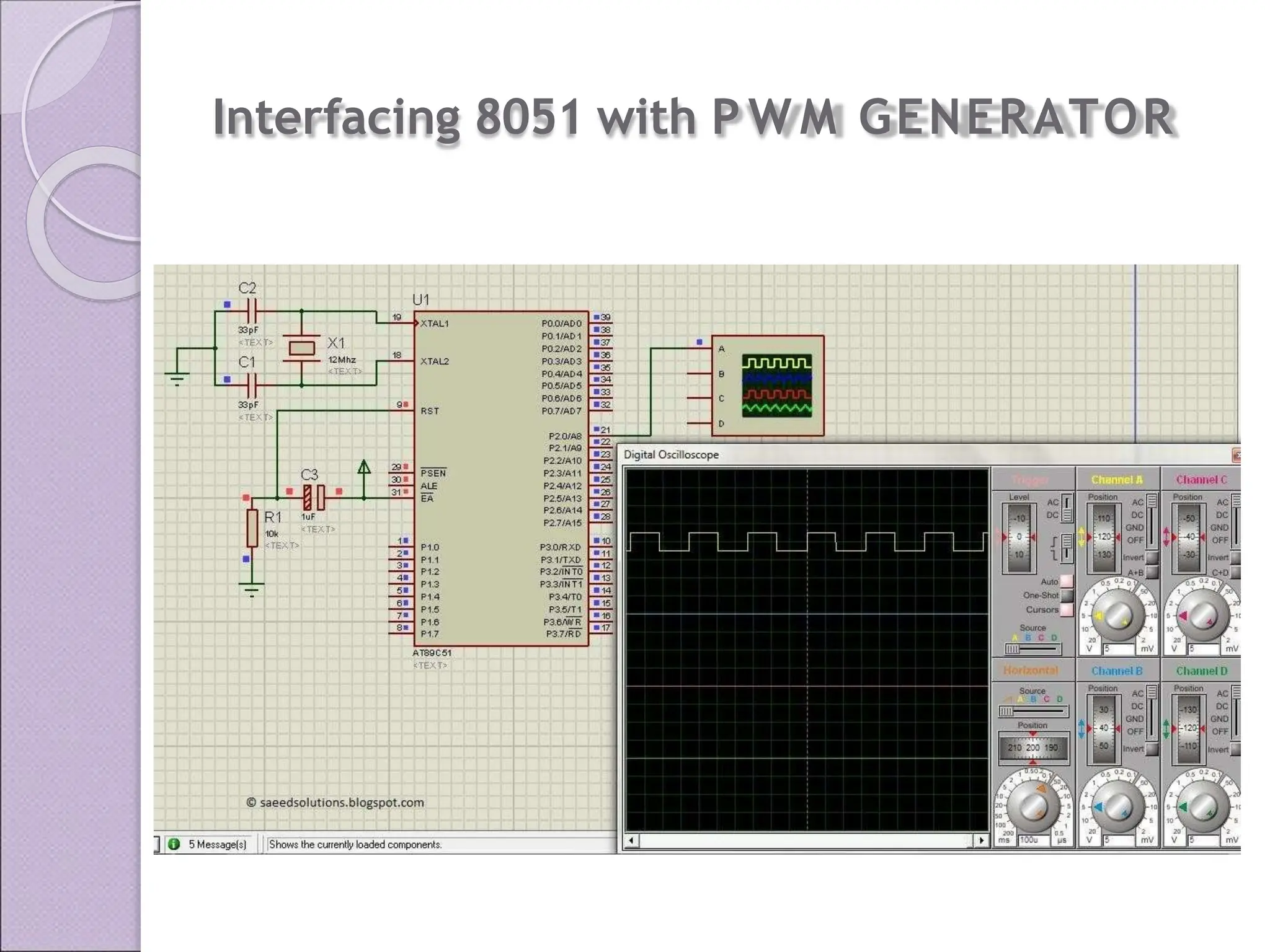
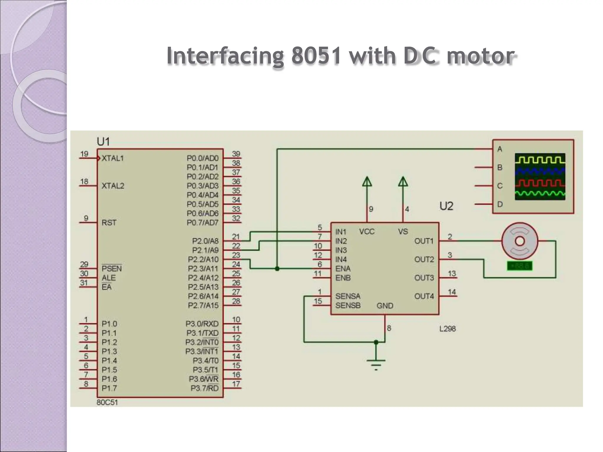
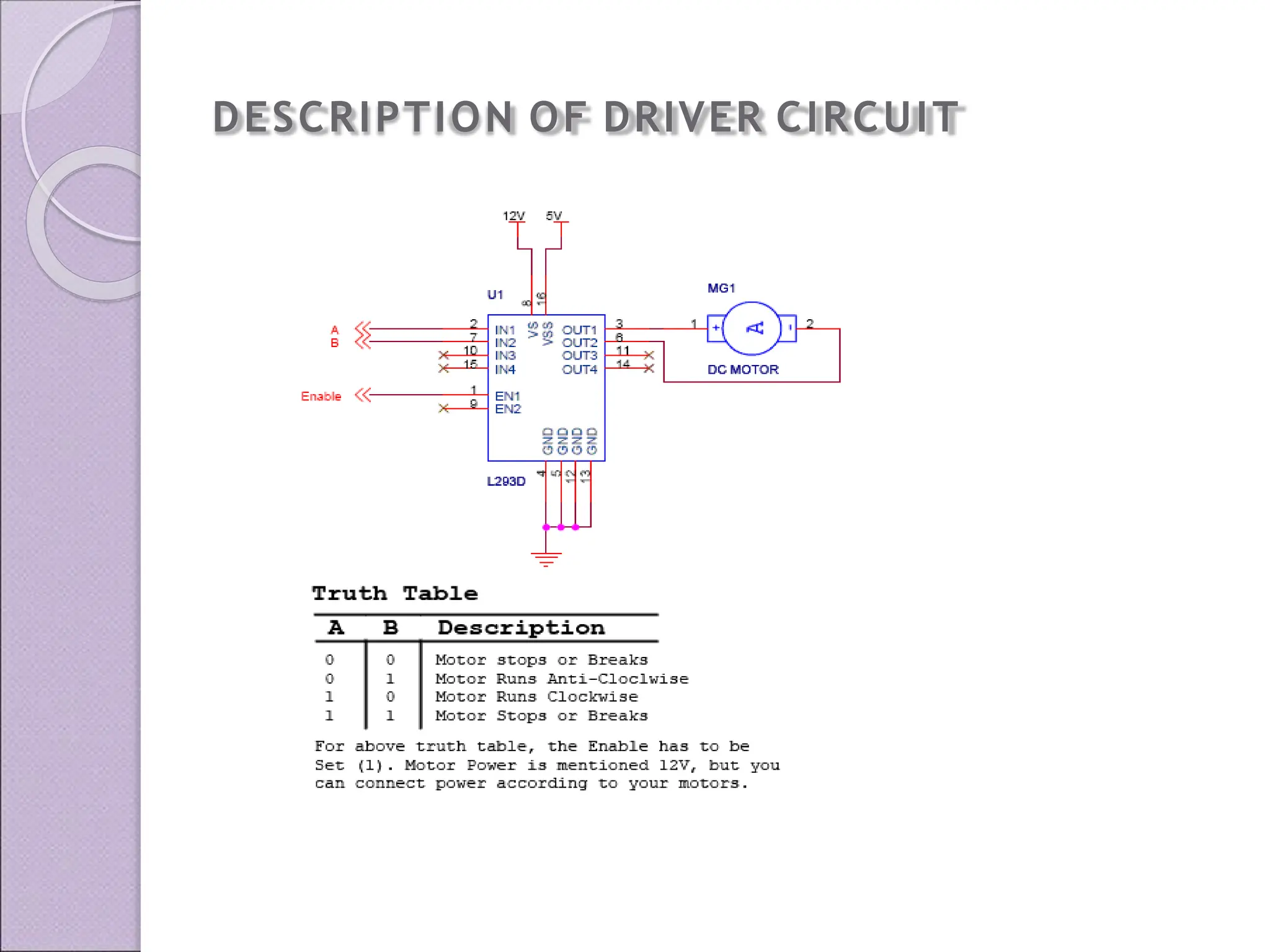
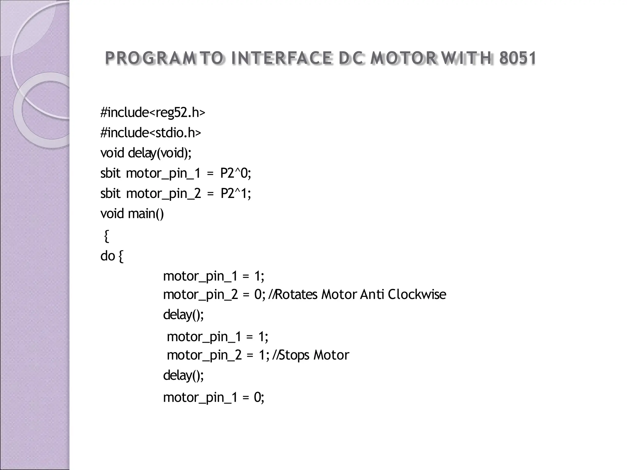
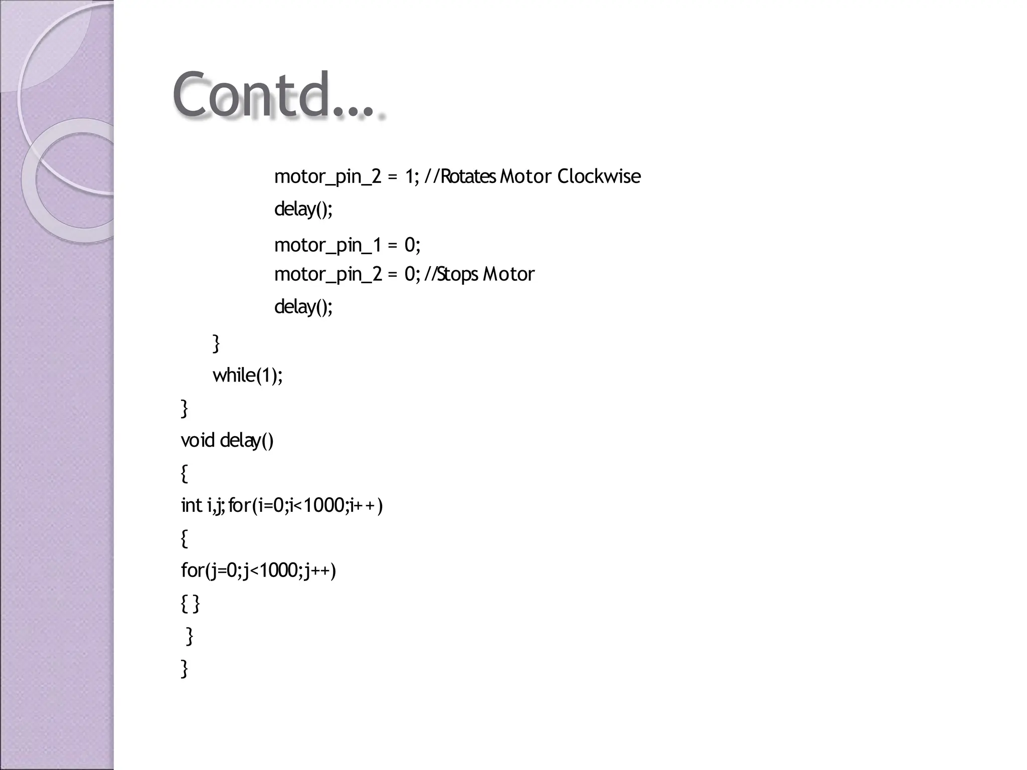
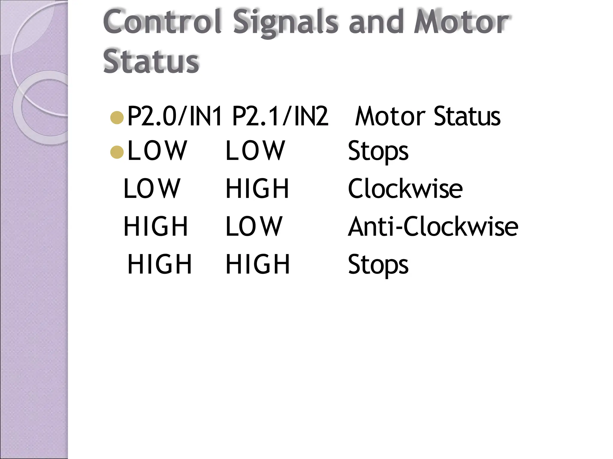
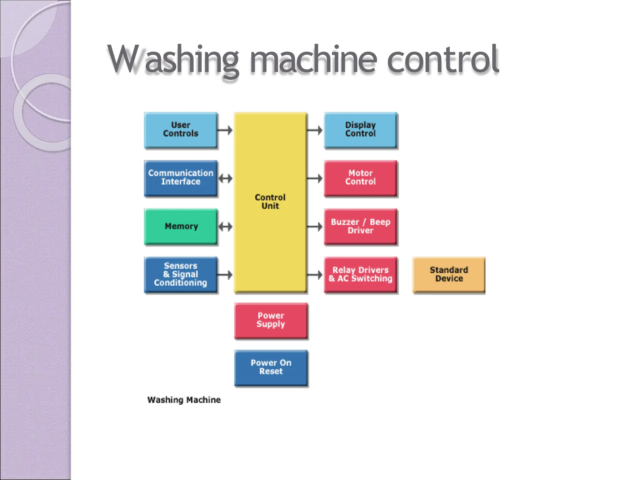
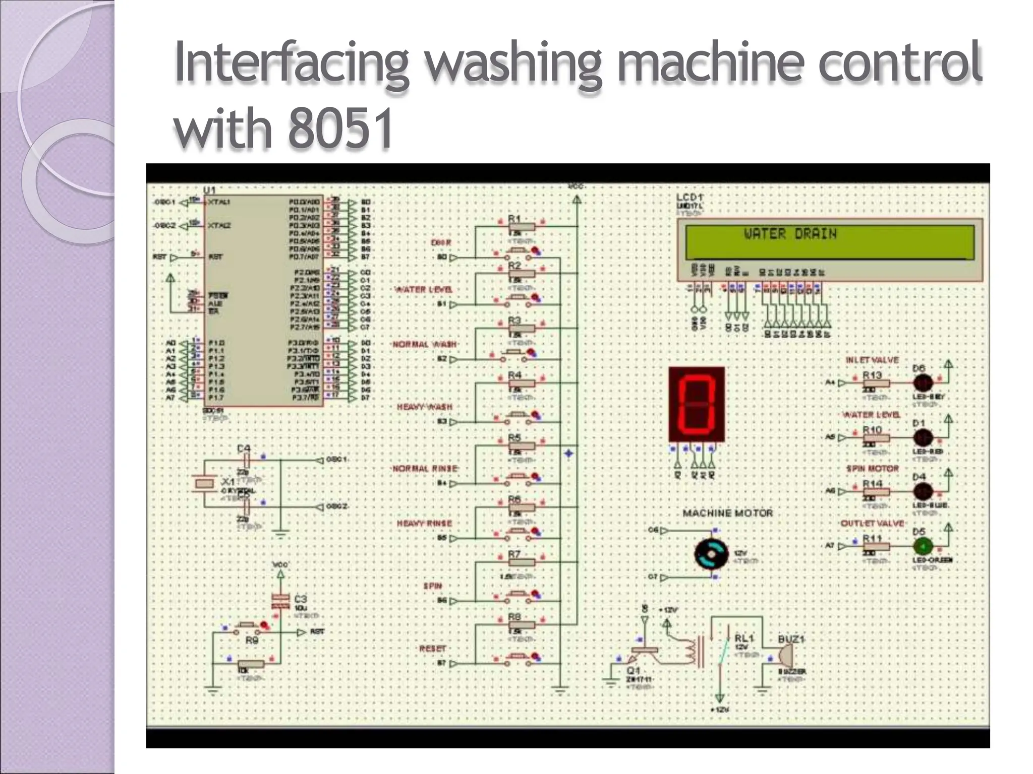
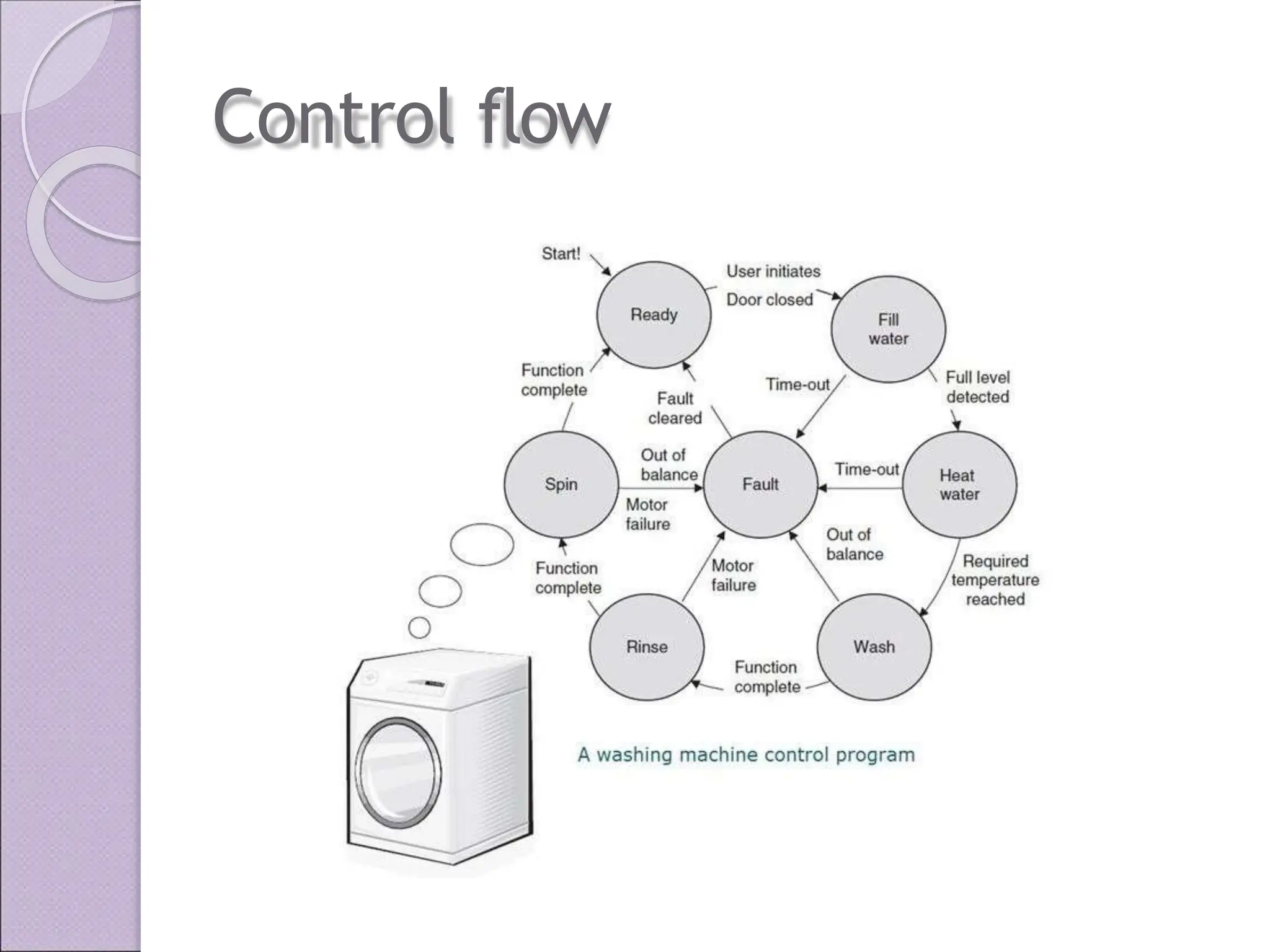
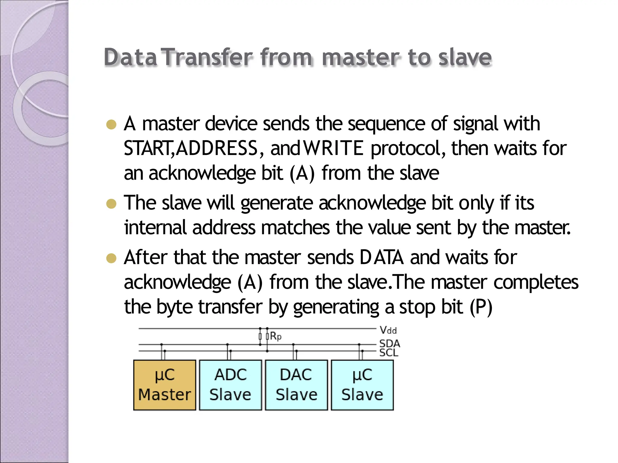
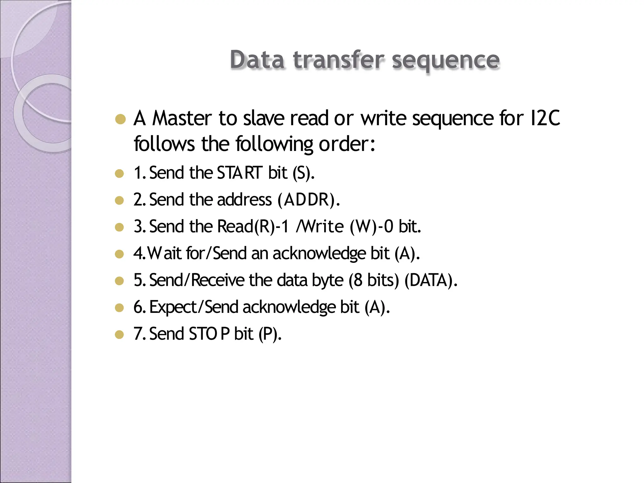
Unit-V
8051 MicrocontrollerApplications
By
S.Sayeekumar ,AP/RMDEEE
MICROPROCESSORS AND
MICROCONTROLLERS
⚫ Microprocessor is used for GENERAL
purposes.
⚫ It is the heart of the computer
.
⚫ T
o use microprocessor other components such
as
◦ Memory &
◦ Components for receiving and sending data
must be added to it.
MICRO C O N TROLLERS
⚫Microcontrollers is designed for SPECIAL
purpose.
⚫No other external components are
needed for its application because all
peripherals are built into it.
EMBEDDED SYSTEMS
⚫ Embedded technology is that exclusively
written software is embedded inside the
custom built hardware to do specific function.
⚫The advantages are
◦ higher performance,
lower power consumption
compact size.
Contd…..
⚫The most commonly used
microcontrollers for embedded
systems are
⚫PIC ( Programmable Interrupt Controller)
⚫8051 belongs toATMEL 89C51 family
.
8051 MicrocontrollerArchitecture
andApplications
⚫ The 8051 Microcontroller was designed in
1980’
s by Intel.
⚫ Developed for embedded system applications.
⚫ “There are many applications with8051
microcontroller
.So,8051 Microcontroller
Projects have great significance in Engineering final
year
.”
FEATURES
8-bit CPU
4k bytes ROM for the program
128 BYTES of RAM for variables
32 I/O lines ( 4 PORTS WITH 8 EACH )
2 timers
1 Serial port
6 interrupt
PIN DETAILS
IN TERFACIN G WIT H 8051
⚫Interfacing of 8051 with
◦ Relay
◦ PWM Generator
◦ DC Motor
◦ Stepper Motor
STEPPER MOTOR
⚫ A stepper motor is an electromechanical device
which converts electrical pulses into discrete
mechanical movements or steps.
⚫ This motor divides a full rotation of 360
degrees into a number of equal steps.
Interfacing Stepper Motor with 8051
⚫
We now want to control a stepper motor in 8051 .It
works by turning ON &OFF afour I/O port lines
generating at a particular frequency
.
⚫
The 8051 has four numbers of I/O port lines,connected
with I/O Port lines (P0.0 – P0.3) to rotate the stepper
motor.
⚫ ULN2003 is a high voltage and high current Darlington
array IC.
⚫ ULN2003 is used as a driver for port I/O lines,drivers
output connected to stepper motor, connector
provided for external power supply if needed.
Pin Assignment with 8051
C Program to control stepper motor
using 8051
//Define 8051 registers
⚫ #include <reg51.h>
#include<stdio.h>
void DelayMs(unsigned int); //Delay function
//Delay 20msec
//----------------------------------
// Main Program
//----------------------------------
void Clockwise (void)
{
unsigned int i;
for (i=0;i<30;i++)
{
P0 = 0x01;DelayMs(5);
P0 = 0x02;DelayMs(5);
P0 = 0x04;DelayMs(5);
P0 = 0x08;DelayMs(5);
}
}
C Program to control stepper motor using 8051
Contd….
⚫ voidAntiClockwise (void)
{
unsigned int i;
for (i=0;i<30;i++)
{
//Delay 20msec
P0 = 0x08;DelayMs(5);
P0 = 0x04;DelayMs(5);
P0 = 0x02;DelayMs(5);
P0 = 0x01;DelayMs(5);
}
}
void main (void)
{
P0 = 0; //Initialize Port0
//Loop Forever
while(1)
{
Clockwise ();
DelayMs (100);
P0 = 0;
AntiClockwise ();
DelayMs (100);
P0 = 0;
}
}
RELAY
⚫ A relay is an electrically operated switch. Relays are
used where it is necessary to control a circuit by a low-
power signal (with complete electrical isolation
between control and controlled circuits),or where
several circuits must be controlled by one signal.
⚫ A relay opens and closes under control of another
electrical circuit.It is therefore connected to output
pins of the microcontroller and used to turn on/off
high-power devices such as motors, transformers,
heaters,bulbs,antenna systems etc Relay is connected
to port 1.0
C Program to control relay using 8051
#include<stdio.h>
sbit relay_pin = P2^0;
void Delay_ms(int);
void main()
{
do
{
relay_pin = 1;//R
elay ON
Delay_ms(1000);
relay_pin = 0;//R
elay OFF
Delay_ms(1000);
}while(1);
}
void Delay_ms(int k)
{ int j;int i;
for(i=0;i<k;i++)
{
for(j=0;j<100;j++)
{ }
}
}
Interfacing 8051 with P W M GENERATOR
⚫ Pulse-width modulation (PWM), or pulse-duration
modulation (PDM), is amodulation technique thatconforms the
width of the pulse,the pulse duration,based on modulator signal
information.Although this modulation technique can be used to
encode information for transmission,its main use is to allow the
control of the power supplied to electrical devices,especially to
inertial loads such as motors.
⚫ The term dutycycledescribes the proportion of 'on' time to the
regular interval or 'period' of time;a low duty cycle corresponds to
low power
,because the power is off for most of the time.Duty
cycle is expressed in percent,100% being fully on.
Interfacing 8051 with P W M GENERATOR
Contd…
⚫ By changing the width of the pulse applied to
the DC motor we can increase or decrease the
amount of power to the motor and increase or
decrease the motor speed.
⚫ The voltage have fixed amplitude but variable
duty cycle.If the pulse is wider then the speed
will be higher and if the pulse is smaller then
the speed will be lower
.
Interfacing 8051 with P W M GENERATOR
Contd…
⚫ If the PWM circuitry is embedded in the chip,
we have to load the registers with high and low
pulses then microcontroller will take remaining
controls.
⚫ If the PWM circuitry is not embedded in the
chip,we have to create various duty cycle pulses
using software.
Interfacing 8051 with P W M GENERATOR
Interfacing 8051 with D C motor
⚫ D C Motors are small,inexpensive and powerful motors used
widely in robotics for their small size and high energy out.A typical
D C motor operates atspeeds thatare fartoo high speed to be
useful,and torque that are too low.Gear’s reduce the speed of
motor and increases the torque.
⚫ The maximum current that canbe sourced or sunk from a8051
microcontroller is 15 mA at 5v
.But a DC Motor need currents
very much more than that and it need voltages 6v
,12v
,24v etc,
depending upon the type of motor used.Another problem is that
the back emf produced by the motor may affect the proper
functioning of the microcontroller.Due to these reasons we can’t
connect a DC Motor directly to a microcontroller.
Interfacing 8051 with D C motor
DESCRIPTION OF DRIVER CIRCUIT
PROGRAM TO INTERFACE D C MOTOR W ITH 8051
#include<reg52.h>
#include<stdio.h>
void delay(void);
sbit motor_pin_1 = P2^0;
sbit motor_pin_2 = P2^1;
void main()
{
do {
motor_pin_1 = 1;
motor_pin_2 = 0;/
/
Rotates Motor Anti Clockwise
delay();
motor_pin_1 = 1;
motor_pin_2 = 1;/
/
Stops Motor
delay();
motor_pin_1 = 0;
Contd…
motor_pin_2 = 1;//Rotates Motor Clockwise
delay();
motor_pin_1 = 0;
motor_pin_2 = 0;//Stops Motor
delay();
}
while(1);
}
void delay()
{
int i,j;for(i=0;i<1000;i++)
{
for(j=0;j<1000;j++)
{ }
}
}
Control Signals and Motor
Status
⚫P2.0/IN1 P2.1/IN2 Motor Status
⚫LOW LOW Stops
LOW HIGH Clockwise
HIGH LOW Anti-Clockwise
HIGH HIGH Stops
Implementation of Traffic Light
Controller using 8051
⚫ Traffic lights or traffic signals are signaling
devices positioned at road intersections,
pedestrian crossings and other locations to
control competing flows of traffic.
Implementation of traffic light controller
using 8051
⚫ Traffic lights alternate the right of way of road users by displaying
lights of astandard color (red, yellow/amber
,and green), using a
universal color code.
In the typical sequence of colored lights:
Illumination of the green light allows traffic to proceed in the
direction denoted,
⚫ Illumination of the yellow/amber light denoting,if safe to do so,
prepare to stop short of the intersection,and
⚫ Illumination of the red signal prohibits any traffic from proceeding.
PIN ASSIGNMENT WITH 8051
LAN Direction 8051 Lines LED’s Traffic Light Controller
P3.2 D8-Stop
NORTH D9-Listen
P3.3
P3.4 D10-Go
P3.5 D11-Stop
WEST P3.6 D12-Listen
P3.7 D13-Go
P1.0 D14-Stop
SOUTH P1.1 D15-Listen
P1.2 D16-Go
P1.3 D17-Stop
EAST P1.4 D18-Listen
P1.5 D19-Go
Note : Make SW32 to “Traffic” label marking position
CIRCUIT DIAGRAM TO INTERFACETRAFFIC LIGHT
Program to control traffic signals
#include <reg51.h>
sbit RA =
sbitYA =
sbit GA =
sbit RB =
sbitYB =
sbit GB =
sbit RC =
sbitYC =
sbit GC =
sbit rD =
sbitYD =
sbit GD =
P1^0;
P1^1;
P1^2;
P3^2;
P3^3;
P3^4;
P3^5;
P3^6;
P3^7;
P1^3;
P1^4;
P1^5;
void Delay (void)
{
unsigned int i,j;
for (i=0;i<200;i++)
for (j=0;j<500;j++);
}
void SuperDelay ()
{
unsigned int i;
for (i=0;i<25;i++)
Delay();
}
1; YA = 0;
void main ()
{
P3 = 0;
while (1)
{
RA =
RB =
RC =
rD =
0; GA =
1; GB =
1; GC =
1; GD =
0; YB = 0;
0; YC = 0;
0; YD = 0;
SuperDelay();
GA = 0; YA = 1;
Delay();
RA = 1; GA =
RB = 0; GB =
RC = 1; GC =
rD = 1; GD =
0; YA = 0;
1; YB = 0;
0; YC = 0;
0; YD = 0;
SuperDelay ();
GB = 0; YB = 1;
Delay ();
0; YA = 0;
RA = 1; GA =
RB = 1; GB =
RC = 0; GC =
rD = 1; GD =
0; YB = 0;
1; YC = 0;
0; YD = 0;
SuperDelay ();
GC = 0; YC = 1;
Delay();
RA = 1; GA =
RB = 1; GB =
RC = 1; GC =
rD = 0; GD =
0; YA = 0;
0; YB = 0;
0; YC = 0;
1; YD = 0;
SuperDelay ();
GD = 0; YD = 1;
Delay();
}
}
Washing machine control
Interfacing washing machine control
with 8051
Control flow
Interfacing I2C - Inter integrated circuit
serial bus
⚫ At any time the electrical power is turned off,the
Microcontroller will start from initial state after power
is turned on,losing all intermediate states.
⚫ To avoid this problem a Serial EEPROM is
⚫ interfaced to the microcontroller via I2C serial BUS.
⚫ This is a two wire bus using a protocol to transfer data
between microcontroller and serial memory and save
the status of process event sequentially
DataTransfer from master to slave
⚫ A master device sends the sequence of signal with
START
,ADDRESS, andWRITE protocol, then waits for
an acknowledge bit (A) from the slave
⚫ The slave will generate acknowledge bit only if its
internal address matches the value sent by the master
.
⚫ After that the master sends DATA and waits for
acknowledge (A) from the slave.The master completes
the byte transfer by generating a stop bit (P)
Data transfer sequence
⚫ A Master to slave read or write sequence for I2C
follows the following order:
⚫ 1.Send the START bit (S).
⚫ 2.Send the address (ADDR).
⚫ 3.Send the Read(R)-1 /Write (W)-0 bit.
⚫ 4.Wait for/Send an acknowledge bit (A).
⚫ 5.Send/Receive the data byte (8 bits) (DATA).
⚫ 6.Expect/Send acknowledge bit (A).
⚫ 7.Send STOP bit (P).

8051 - microcontroller applications.pptx

  • 1.
  • 2.
    MICROPROCESSORS AND MICROCONTROLLERS ⚫ Microprocessoris used for GENERAL purposes. ⚫ It is the heart of the computer . ⚫ T o use microprocessor other components such as ◦ Memory & ◦ Components for receiving and sending data must be added to it.
  • 3.
    MICRO C ON TROLLERS ⚫Microcontrollers is designed for SPECIAL purpose. ⚫No other external components are needed for its application because all peripherals are built into it.
  • 4.
    EMBEDDED SYSTEMS ⚫ Embeddedtechnology is that exclusively written software is embedded inside the custom built hardware to do specific function. ⚫The advantages are ◦ higher performance, lower power consumption compact size.
  • 5.
    Contd….. ⚫The most commonlyused microcontrollers for embedded systems are ⚫PIC ( Programmable Interrupt Controller) ⚫8051 belongs toATMEL 89C51 family .
  • 6.
    8051 MicrocontrollerArchitecture andApplications ⚫ The8051 Microcontroller was designed in 1980’ s by Intel. ⚫ Developed for embedded system applications. ⚫ “There are many applications with8051 microcontroller .So,8051 Microcontroller Projects have great significance in Engineering final year .”
  • 8.
    FEATURES 8-bit CPU 4k bytesROM for the program 128 BYTES of RAM for variables 32 I/O lines ( 4 PORTS WITH 8 EACH ) 2 timers 1 Serial port 6 interrupt
  • 10.
  • 11.
    IN TERFACIN GWIT H 8051 ⚫Interfacing of 8051 with ◦ Relay ◦ PWM Generator ◦ DC Motor ◦ Stepper Motor
  • 12.
    STEPPER MOTOR ⚫ Astepper motor is an electromechanical device which converts electrical pulses into discrete mechanical movements or steps. ⚫ This motor divides a full rotation of 360 degrees into a number of equal steps.
  • 13.
    Interfacing Stepper Motorwith 8051 ⚫ We now want to control a stepper motor in 8051 .It works by turning ON &OFF afour I/O port lines generating at a particular frequency . ⚫ The 8051 has four numbers of I/O port lines,connected with I/O Port lines (P0.0 – P0.3) to rotate the stepper motor. ⚫ ULN2003 is a high voltage and high current Darlington array IC. ⚫ ULN2003 is used as a driver for port I/O lines,drivers output connected to stepper motor, connector provided for external power supply if needed.
  • 14.
  • 15.
    C Program tocontrol stepper motor using 8051 //Define 8051 registers ⚫ #include <reg51.h> #include<stdio.h> void DelayMs(unsigned int); //Delay function //Delay 20msec //---------------------------------- // Main Program //---------------------------------- void Clockwise (void) { unsigned int i; for (i=0;i<30;i++) { P0 = 0x01;DelayMs(5); P0 = 0x02;DelayMs(5); P0 = 0x04;DelayMs(5); P0 = 0x08;DelayMs(5); } }
  • 16.
    C Program tocontrol stepper motor using 8051 Contd…. ⚫ voidAntiClockwise (void) { unsigned int i; for (i=0;i<30;i++) { //Delay 20msec P0 = 0x08;DelayMs(5); P0 = 0x04;DelayMs(5); P0 = 0x02;DelayMs(5); P0 = 0x01;DelayMs(5); } } void main (void) { P0 = 0; //Initialize Port0 //Loop Forever while(1) { Clockwise (); DelayMs (100); P0 = 0; AntiClockwise (); DelayMs (100); P0 = 0; } }
  • 17.
    RELAY ⚫ A relayis an electrically operated switch. Relays are used where it is necessary to control a circuit by a low- power signal (with complete electrical isolation between control and controlled circuits),or where several circuits must be controlled by one signal. ⚫ A relay opens and closes under control of another electrical circuit.It is therefore connected to output pins of the microcontroller and used to turn on/off high-power devices such as motors, transformers, heaters,bulbs,antenna systems etc Relay is connected to port 1.0
  • 18.
    C Program tocontrol relay using 8051 #include<stdio.h> sbit relay_pin = P2^0; void Delay_ms(int); void main() { do { relay_pin = 1;//R elay ON Delay_ms(1000); relay_pin = 0;//R elay OFF Delay_ms(1000); }while(1); } void Delay_ms(int k) { int j;int i; for(i=0;i<k;i++) { for(j=0;j<100;j++) { } } }
  • 19.
    Interfacing 8051 withP W M GENERATOR ⚫ Pulse-width modulation (PWM), or pulse-duration modulation (PDM), is amodulation technique thatconforms the width of the pulse,the pulse duration,based on modulator signal information.Although this modulation technique can be used to encode information for transmission,its main use is to allow the control of the power supplied to electrical devices,especially to inertial loads such as motors. ⚫ The term dutycycledescribes the proportion of 'on' time to the regular interval or 'period' of time;a low duty cycle corresponds to low power ,because the power is off for most of the time.Duty cycle is expressed in percent,100% being fully on.
  • 20.
    Interfacing 8051 withP W M GENERATOR Contd… ⚫ By changing the width of the pulse applied to the DC motor we can increase or decrease the amount of power to the motor and increase or decrease the motor speed. ⚫ The voltage have fixed amplitude but variable duty cycle.If the pulse is wider then the speed will be higher and if the pulse is smaller then the speed will be lower .
  • 21.
    Interfacing 8051 withP W M GENERATOR Contd… ⚫ If the PWM circuitry is embedded in the chip, we have to load the registers with high and low pulses then microcontroller will take remaining controls. ⚫ If the PWM circuitry is not embedded in the chip,we have to create various duty cycle pulses using software.
  • 22.
    Interfacing 8051 withP W M GENERATOR
  • 23.
    Interfacing 8051 withD C motor ⚫ D C Motors are small,inexpensive and powerful motors used widely in robotics for their small size and high energy out.A typical D C motor operates atspeeds thatare fartoo high speed to be useful,and torque that are too low.Gear’s reduce the speed of motor and increases the torque. ⚫ The maximum current that canbe sourced or sunk from a8051 microcontroller is 15 mA at 5v .But a DC Motor need currents very much more than that and it need voltages 6v ,12v ,24v etc, depending upon the type of motor used.Another problem is that the back emf produced by the motor may affect the proper functioning of the microcontroller.Due to these reasons we can’t connect a DC Motor directly to a microcontroller.
  • 24.
  • 25.
  • 26.
    PROGRAM TO INTERFACED C MOTOR W ITH 8051 #include<reg52.h> #include<stdio.h> void delay(void); sbit motor_pin_1 = P2^0; sbit motor_pin_2 = P2^1; void main() { do { motor_pin_1 = 1; motor_pin_2 = 0;/ / Rotates Motor Anti Clockwise delay(); motor_pin_1 = 1; motor_pin_2 = 1;/ / Stops Motor delay(); motor_pin_1 = 0;
  • 27.
    Contd… motor_pin_2 = 1;//RotatesMotor Clockwise delay(); motor_pin_1 = 0; motor_pin_2 = 0;//Stops Motor delay(); } while(1); } void delay() { int i,j;for(i=0;i<1000;i++) { for(j=0;j<1000;j++) { } } }
  • 28.
    Control Signals andMotor Status ⚫P2.0/IN1 P2.1/IN2 Motor Status ⚫LOW LOW Stops LOW HIGH Clockwise HIGH LOW Anti-Clockwise HIGH HIGH Stops
  • 29.
    Implementation of TrafficLight Controller using 8051 ⚫ Traffic lights or traffic signals are signaling devices positioned at road intersections, pedestrian crossings and other locations to control competing flows of traffic.
  • 30.
    Implementation of trafficlight controller using 8051 ⚫ Traffic lights alternate the right of way of road users by displaying lights of astandard color (red, yellow/amber ,and green), using a universal color code. In the typical sequence of colored lights: Illumination of the green light allows traffic to proceed in the direction denoted, ⚫ Illumination of the yellow/amber light denoting,if safe to do so, prepare to stop short of the intersection,and ⚫ Illumination of the red signal prohibits any traffic from proceeding.
  • 31.
  • 32.
    LAN Direction 8051Lines LED’s Traffic Light Controller P3.2 D8-Stop NORTH D9-Listen P3.3 P3.4 D10-Go P3.5 D11-Stop WEST P3.6 D12-Listen P3.7 D13-Go P1.0 D14-Stop SOUTH P1.1 D15-Listen P1.2 D16-Go P1.3 D17-Stop EAST P1.4 D18-Listen P1.5 D19-Go Note : Make SW32 to “Traffic” label marking position
  • 33.
    CIRCUIT DIAGRAM TOINTERFACETRAFFIC LIGHT
  • 34.
    Program to controltraffic signals #include <reg51.h> sbit RA = sbitYA = sbit GA = sbit RB = sbitYB = sbit GB = sbit RC = sbitYC = sbit GC = sbit rD = sbitYD = sbit GD = P1^0; P1^1; P1^2; P3^2; P3^3; P3^4; P3^5; P3^6; P3^7; P1^3; P1^4; P1^5;
  • 35.
    void Delay (void) { unsignedint i,j; for (i=0;i<200;i++) for (j=0;j<500;j++); } void SuperDelay () { unsigned int i; for (i=0;i<25;i++) Delay(); }
  • 36.
    1; YA =0; void main () { P3 = 0; while (1) { RA = RB = RC = rD = 0; GA = 1; GB = 1; GC = 1; GD = 0; YB = 0; 0; YC = 0; 0; YD = 0; SuperDelay(); GA = 0; YA = 1; Delay(); RA = 1; GA = RB = 0; GB = RC = 1; GC = rD = 1; GD = 0; YA = 0; 1; YB = 0; 0; YC = 0; 0; YD = 0; SuperDelay ();
  • 37.
    GB = 0;YB = 1; Delay (); 0; YA = 0; RA = 1; GA = RB = 1; GB = RC = 0; GC = rD = 1; GD = 0; YB = 0; 1; YC = 0; 0; YD = 0; SuperDelay (); GC = 0; YC = 1; Delay(); RA = 1; GA = RB = 1; GB = RC = 1; GC = rD = 0; GD = 0; YA = 0; 0; YB = 0; 0; YC = 0; 1; YD = 0; SuperDelay (); GD = 0; YD = 1; Delay(); } }
  • 38.
  • 39.
    Interfacing washing machinecontrol with 8051
  • 40.
  • 41.
    Interfacing I2C -Inter integrated circuit serial bus ⚫ At any time the electrical power is turned off,the Microcontroller will start from initial state after power is turned on,losing all intermediate states. ⚫ To avoid this problem a Serial EEPROM is ⚫ interfaced to the microcontroller via I2C serial BUS. ⚫ This is a two wire bus using a protocol to transfer data between microcontroller and serial memory and save the status of process event sequentially
  • 42.
    DataTransfer from masterto slave ⚫ A master device sends the sequence of signal with START ,ADDRESS, andWRITE protocol, then waits for an acknowledge bit (A) from the slave ⚫ The slave will generate acknowledge bit only if its internal address matches the value sent by the master . ⚫ After that the master sends DATA and waits for acknowledge (A) from the slave.The master completes the byte transfer by generating a stop bit (P)
  • 43.
    Data transfer sequence ⚫A Master to slave read or write sequence for I2C follows the following order: ⚫ 1.Send the START bit (S). ⚫ 2.Send the address (ADDR). ⚫ 3.Send the Read(R)-1 /Write (W)-0 bit. ⚫ 4.Wait for/Send an acknowledge bit (A). ⚫ 5.Send/Receive the data byte (8 bits) (DATA). ⚫ 6.Expect/Send acknowledge bit (A). ⚫ 7.Send STOP bit (P).