UEEG002
Medical Instrumentation –
Introduction,Bioamplifiers
D.Poornima,AP(Sr.Gr)/EEE,
Sri Ramakrishna Institute of Technology,
Coimbatore.
Introduction
What is Medical Instrumentation??
• Application of biomedical engineering
• Focuses on the devices and mechanics used to measure, evaluate,
and treat biological systems.
• Uses multiple sensors to monitor physiological characteristics of a
human or animal.
• Helps physicians to diagnose the problem and provide treatment,
to measure biological signals and to design a medical instrument.
• Originated as a necessity to constantly monitor vital signs of
Astronauts during NASA's Mercury, Gemini, and Apollo missions
Components of Biomedical Instrumentation
System
• Any medical instrument consists of the following functional
basic parts
– Measurand
– Sensor / Transducer
– Signal Conditioner
– Display
– Data Storage and
Data Transmission
• Measurand
– The measurand is the physical quantity,property or condition that instrumentation
system measures. Human body acts as the source for measurand, and it generates
bio-signals.
Example: Blood pressure (Internal)
Electrocardiograms (on the body surface)
Blood or Biopsy (Emanate from the body)
• Sensor / Transducer
– Converts one form of energy to another form usually electrical energy.
– The transducer produces a usable output depending on the measurand.
– The sensor is used to sense the signal from the source. It is used to interface
the signal with the human
Example: Piezoelectric signal which converts mechanical vibrations into the
electrical signal
• Signal Conditioner
– Used to convert the output from the transducer into an electrical
value.
– The instrument system sends this quantity to the display or recording
system.
– signal conditioning process includes amplification, filtering, analogue to
digital and Digital to analogue conversions.
– Signal conditioning improves the sensitivity of instruments.
• Display
– Provides a visual representation of the measured parameter or
quantity.
Example: Chart recorder, Cathode Ray oscilloscope (CRO).
– Sometimes alarms are used to hear the audio signals.
Example: Signals generated in Doppler Ultrasound Scanner used for
Fetal Monitoring.
• Data Storage and Data Transmission
– Data storage is used to store the data and can be used for future reference.
– Recent days Electronic Health records are utilized in hospitals.
– Data transmission is used in Telemetric systems, where data can be transmitted from
one location to another remotely.
Bioelectric Potential
• Human body has many subsystems inside it like
– Cardiovascular system
– Respiratory system
– Nervous system
– Digestive system
• The systems in the human body generate their own monitoring signals when
they carry out their functions.
• These signals provide useful information about their function.
• These signals are bioelectric potentials associated with nerve conduction,
brain activity, heartbeat, muscle activity and so on.
• Bioelectric potentials are actually ionic voltages produced as a result of
electro chemical activity of certain cell.
• Transducers are used to convert these ionic potentials in to electrical signals
Cell Structure
• Certain types of cells within the body, such as nerve and muscle cells are
encased in a semi permeable membrane.
• This membrane permits some substances to pass through while others
are kept out.
• Surrounding the cells of the body are the body fluids.
• These fluids are conductive solutions containing charged atoms know as
ions.
• The principle ions are sodium (Na+) Potassium (K+) and chloride (Cl-).
• The membrane of excitable cells permits entry of
Potassium (K+) and chloride(C-) ions but blocks
the entry of sodium (Na+) ions.
Resting Potential
• So potential inside the cell is more negative than outside cell.
• This membrane potential is called Resting potentials.
• This potential is measured from inside the cell with respect to body fluids.
• So resting potential of a cell is negative.
• This resting potential ranging from -60mv to -100 mv.
• Cell in the resting state is called polarized cell.
Action Potential [Depolarization]
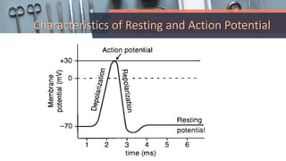
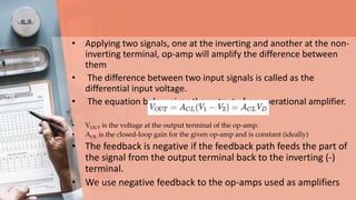
• When a section of a cell membrane is excited by the flow of
ionic current or by some form of externally applied energy,
the membrane allows some Na+ and try to reach some
balance of potential inside and outside.
• Same time some K+ goes outside but not rapidly like
sodium.
• As a result, the cell has slightly Positive potential on the
inside Due to the imbalance of the Potassium ions.
• This potential is known as “action potential” and is
approximately +20 mV
• A cell that has been excited and that displays an action potential is said to
be depolarized
• The process from resting to action potential is called depolarization.
• Action potential is always positive inside.
Reploarization
• The process of the cell coming to
depolarised state from polarised state
Characteristics of Resting and Action Potential
Bio potential Amplifiers
– Very important part of modern medical instrumentation
– To amplify biopotentials which are generated in the body at
low levels with high source impedance
– are required to increase signal strength while maintaining
fidelity
• Functions of Biopotential Amplifiers
– To take a weak bio-potential and increase its amplitude so
that it can be processed, recorded or displayed
– To amplify voltage, power and current.
– Sometimes used to isolate the load from the source current
gain only
• Characteristics of Biopotential Amplifiers
– High input impedance
– Low output impedance
– The biopotential amplifier must be sensitive to important
frequency components of the biosignal
– Biopotential amplifiers have a gain of 1000 or greater
– Most biopotential amplifiers are differential
– High common mode rejection ratio.
Types of Bio Amplifiers
1. Differential Amplifier
2. Operational Amplifier
3. Instrumentation Amplifier
4. Isolation Amplifier
Differential Amplifier
• Type of electronic amplifier that amplifies the difference between two
input voltages but suppresses any voltage common to the two inputs.
• A differential amplifier is an analog circuit with two inputs (V1 and V2)
and one output (V0) in which the output is ideally proportional to the
difference between the two voltages.
• The formula for a simple differential amplifier can be expressed:
• V0 is the output voltage
• V1 and V2 are the input voltages
• Ad is the gain of the amplifier (i.e. the differential amplifier gain)
• When V1 = V2, V0 is equal to zero, and hence the output voltage is
suppressed.
• But any difference between inputs V1 and V2 is multiplied
by the differential amplifier gain Ad.
• It is also known as a difference amplifier
– the difference between the input
voltages is amplified.
Operational Amplifier
• Op amp is basically a multistage amplifier in which several amplifier stages are
interconnected to each other in a very complicated manner.
• Its internal circuit consists of many transistors, FETs and resistors. All this occupies
a very little space.
• It is packed in a small package and is available in the Integrated Circuit (IC)form.
• The term Op Amp is used to denote
an amplifier which can be configured
to perform various operations like
amplification, subtraction,
differentiation, addition, integration etc
• Applying two signals, one at the inverting and another at the non-
inverting terminal, op-amp will amplify the difference between
them
• The difference between two input signals is called as the
differential input voltage.
• The equation below gives the output of an operational amplifier.
• VOUT is the voltage at the output terminal of the op-amp.
• AOL is the closed-loop gain for the given op-amp and is constant (ideally)
• The feedback is negative if the feedback path feeds the part of
the signal from the output terminal back to the inverting (-)
terminal.
• We use negative feedback to the op-amps used as amplifiers
Chopper Amplifier
• This circuit uses a chopping device which converts slowly varying dc
to an alternating form with amplitude proportional to the input
direct current and phase depends on the polarity of original signal.
• The ac voltage is then amplified by an ac amplifier whose output is
then rectified back to get an amplified direct current.
• Figure shows single ended chopper stabilizer amplifier.
• Aim of this circuit is to avoid the dc offset voltage present in the
output signal.
• For that purpose first convert the dc signal into ac using a chopper
Components
• Low Pass Filter
– The low frequency components derived from the input signal by passing it through low
pass filter R2C2 and R2
• Chopper
– The output of LPF is then chopped using a transistor switch w.r.t a carrier signal from
the oscillator.
• Demodulator
The original signal recovered in demodulator which is again applied to second stage of
amplification.
• Low Pass Filter
– Before given to the amplifier low frequency components again derived using LPF
• Second Stage of Amplification (A2)
– At the input of A2 an HPF C1R1 is used to derive the high frequency signals.
– This is to reduce the dc offset and drift of second amplifier A2.
Instrumentation Amplifier
• Commonly used Bio-potential Amplifier is Differential amplifier. But it has
some limitations.
• These limitations overcome with the availability of improved version of
differential amplifier called Instrumentation Amplifier
• High gain and the high input impedance are attained with an instrumentation
amplifier.
• Usually, a 3-amplifier and 7 resistor setup forms the
instrumentation amplifier circuit.
• The output from the transducer is given as input to the
instrumentation amplifier.
• Before the signal goes to the next stage, a special amplifier is
required with high CMRR, high input impedance and to avoid
loading effects.
• Two buffer amplifiers A1 and A2 connected to a differential
• amplifier A3.
• Op-amp A3 with four equal resistors R form a differential
• amplifier with gain 1.
• Rg = used to set the gain using the formula
• Advantage of Chopper Amplifier
 Insensitivity to component changes due to ageing, temperature change, power
supply variation, or other environmental factors.
 Small offset voltage
 Used to amplify small dc signals of few microvolts.
Isolation Amplifier
• Used for protection against leakage currents
• Isolation between input and output
• Isolation between different supply voltages
and grounds
• Three methods used in the design
– Transformer Isolation
– Optical Isolation
– Capacitive Isolation
• Transformer Isolation
– Uses Frequency modulated or a pulse width modulated carrier signal
– Uses internal DC-DC converter
comprising of a 20kHz oscillator,
transformer, rectifier, and filter
to supply isolated
• Optical Isolation
– Can also be achieved by optical means
– Patient is not connected electrically to hospital line or ground
– Separate battery supplies power to the patient circuit
– Patient bio signal is converted into a light by a light source
– On output side, photo transistor
converts light signal again to
electrical signal
• Capacitive Isolation
– Uses digital encoding of the input voltage and frequency modulation to
send the signal across a differential capacitive barrier
– Separate power supply needed
on both sides of the barrier

Biomedical Instrumentation introduction, Bioamplifiers

  • 1.
  • 2.
    Introduction What is MedicalInstrumentation?? • Application of biomedical engineering • Focuses on the devices and mechanics used to measure, evaluate, and treat biological systems. • Uses multiple sensors to monitor physiological characteristics of a human or animal. • Helps physicians to diagnose the problem and provide treatment, to measure biological signals and to design a medical instrument. • Originated as a necessity to constantly monitor vital signs of Astronauts during NASA's Mercury, Gemini, and Apollo missions
  • 3.
    Components of BiomedicalInstrumentation System • Any medical instrument consists of the following functional basic parts – Measurand – Sensor / Transducer – Signal Conditioner – Display – Data Storage and Data Transmission
  • 4.
    • Measurand – Themeasurand is the physical quantity,property or condition that instrumentation system measures. Human body acts as the source for measurand, and it generates bio-signals. Example: Blood pressure (Internal) Electrocardiograms (on the body surface) Blood or Biopsy (Emanate from the body) • Sensor / Transducer – Converts one form of energy to another form usually electrical energy. – The transducer produces a usable output depending on the measurand. – The sensor is used to sense the signal from the source. It is used to interface the signal with the human Example: Piezoelectric signal which converts mechanical vibrations into the electrical signal
  • 5.
    • Signal Conditioner –Used to convert the output from the transducer into an electrical value. – The instrument system sends this quantity to the display or recording system. – signal conditioning process includes amplification, filtering, analogue to digital and Digital to analogue conversions. – Signal conditioning improves the sensitivity of instruments. • Display – Provides a visual representation of the measured parameter or quantity. Example: Chart recorder, Cathode Ray oscilloscope (CRO). – Sometimes alarms are used to hear the audio signals. Example: Signals generated in Doppler Ultrasound Scanner used for Fetal Monitoring.
  • 6.
    • Data Storageand Data Transmission – Data storage is used to store the data and can be used for future reference. – Recent days Electronic Health records are utilized in hospitals. – Data transmission is used in Telemetric systems, where data can be transmitted from one location to another remotely.
  • 7.
    Bioelectric Potential • Humanbody has many subsystems inside it like – Cardiovascular system – Respiratory system – Nervous system – Digestive system • The systems in the human body generate their own monitoring signals when they carry out their functions. • These signals provide useful information about their function. • These signals are bioelectric potentials associated with nerve conduction, brain activity, heartbeat, muscle activity and so on. • Bioelectric potentials are actually ionic voltages produced as a result of electro chemical activity of certain cell. • Transducers are used to convert these ionic potentials in to electrical signals
  • 8.
  • 9.
    • Certain typesof cells within the body, such as nerve and muscle cells are encased in a semi permeable membrane. • This membrane permits some substances to pass through while others are kept out. • Surrounding the cells of the body are the body fluids. • These fluids are conductive solutions containing charged atoms know as ions. • The principle ions are sodium (Na+) Potassium (K+) and chloride (Cl-). • The membrane of excitable cells permits entry of Potassium (K+) and chloride(C-) ions but blocks the entry of sodium (Na+) ions.
  • 10.
    Resting Potential • Sopotential inside the cell is more negative than outside cell. • This membrane potential is called Resting potentials. • This potential is measured from inside the cell with respect to body fluids. • So resting potential of a cell is negative. • This resting potential ranging from -60mv to -100 mv. • Cell in the resting state is called polarized cell.
  • 11.
    Action Potential [Depolarization] •When a section of a cell membrane is excited by the flow of ionic current or by some form of externally applied energy, the membrane allows some Na+ and try to reach some balance of potential inside and outside. • Same time some K+ goes outside but not rapidly like sodium. • As a result, the cell has slightly Positive potential on the inside Due to the imbalance of the Potassium ions. • This potential is known as “action potential” and is approximately +20 mV
  • 12.
    • A cellthat has been excited and that displays an action potential is said to be depolarized • The process from resting to action potential is called depolarization. • Action potential is always positive inside.
  • 13.
    Reploarization • The processof the cell coming to depolarised state from polarised state
  • 14.
    Characteristics of Restingand Action Potential
  • 15.
    Bio potential Amplifiers –Very important part of modern medical instrumentation – To amplify biopotentials which are generated in the body at low levels with high source impedance – are required to increase signal strength while maintaining fidelity • Functions of Biopotential Amplifiers – To take a weak bio-potential and increase its amplitude so that it can be processed, recorded or displayed – To amplify voltage, power and current. – Sometimes used to isolate the load from the source current gain only
  • 16.
    • Characteristics ofBiopotential Amplifiers – High input impedance – Low output impedance – The biopotential amplifier must be sensitive to important frequency components of the biosignal – Biopotential amplifiers have a gain of 1000 or greater – Most biopotential amplifiers are differential – High common mode rejection ratio.
  • 17.
    Types of BioAmplifiers 1. Differential Amplifier 2. Operational Amplifier 3. Instrumentation Amplifier 4. Isolation Amplifier
  • 18.
    Differential Amplifier • Typeof electronic amplifier that amplifies the difference between two input voltages but suppresses any voltage common to the two inputs. • A differential amplifier is an analog circuit with two inputs (V1 and V2) and one output (V0) in which the output is ideally proportional to the difference between the two voltages. • The formula for a simple differential amplifier can be expressed: • V0 is the output voltage • V1 and V2 are the input voltages • Ad is the gain of the amplifier (i.e. the differential amplifier gain)
  • 19.
    • When V1= V2, V0 is equal to zero, and hence the output voltage is suppressed. • But any difference between inputs V1 and V2 is multiplied by the differential amplifier gain Ad. • It is also known as a difference amplifier – the difference between the input voltages is amplified.
  • 20.
    Operational Amplifier • Opamp is basically a multistage amplifier in which several amplifier stages are interconnected to each other in a very complicated manner. • Its internal circuit consists of many transistors, FETs and resistors. All this occupies a very little space. • It is packed in a small package and is available in the Integrated Circuit (IC)form. • The term Op Amp is used to denote an amplifier which can be configured to perform various operations like amplification, subtraction, differentiation, addition, integration etc
  • 21.
    • Applying twosignals, one at the inverting and another at the non- inverting terminal, op-amp will amplify the difference between them • The difference between two input signals is called as the differential input voltage. • The equation below gives the output of an operational amplifier. • VOUT is the voltage at the output terminal of the op-amp. • AOL is the closed-loop gain for the given op-amp and is constant (ideally) • The feedback is negative if the feedback path feeds the part of the signal from the output terminal back to the inverting (-) terminal. • We use negative feedback to the op-amps used as amplifiers
  • 22.
    Chopper Amplifier • Thiscircuit uses a chopping device which converts slowly varying dc to an alternating form with amplitude proportional to the input direct current and phase depends on the polarity of original signal. • The ac voltage is then amplified by an ac amplifier whose output is then rectified back to get an amplified direct current. • Figure shows single ended chopper stabilizer amplifier. • Aim of this circuit is to avoid the dc offset voltage present in the output signal. • For that purpose first convert the dc signal into ac using a chopper
  • 24.
    Components • Low PassFilter – The low frequency components derived from the input signal by passing it through low pass filter R2C2 and R2 • Chopper – The output of LPF is then chopped using a transistor switch w.r.t a carrier signal from the oscillator. • Demodulator The original signal recovered in demodulator which is again applied to second stage of amplification. • Low Pass Filter – Before given to the amplifier low frequency components again derived using LPF • Second Stage of Amplification (A2) – At the input of A2 an HPF C1R1 is used to derive the high frequency signals. – This is to reduce the dc offset and drift of second amplifier A2.
  • 25.
    Instrumentation Amplifier • Commonlyused Bio-potential Amplifier is Differential amplifier. But it has some limitations. • These limitations overcome with the availability of improved version of differential amplifier called Instrumentation Amplifier • High gain and the high input impedance are attained with an instrumentation amplifier.
  • 26.
    • Usually, a3-amplifier and 7 resistor setup forms the instrumentation amplifier circuit. • The output from the transducer is given as input to the instrumentation amplifier. • Before the signal goes to the next stage, a special amplifier is required with high CMRR, high input impedance and to avoid loading effects. • Two buffer amplifiers A1 and A2 connected to a differential • amplifier A3. • Op-amp A3 with four equal resistors R form a differential • amplifier with gain 1. • Rg = used to set the gain using the formula
  • 28.
    • Advantage ofChopper Amplifier  Insensitivity to component changes due to ageing, temperature change, power supply variation, or other environmental factors.  Small offset voltage  Used to amplify small dc signals of few microvolts.
  • 29.
    Isolation Amplifier • Usedfor protection against leakage currents • Isolation between input and output • Isolation between different supply voltages and grounds • Three methods used in the design – Transformer Isolation – Optical Isolation – Capacitive Isolation
  • 30.
    • Transformer Isolation –Uses Frequency modulated or a pulse width modulated carrier signal – Uses internal DC-DC converter comprising of a 20kHz oscillator, transformer, rectifier, and filter to supply isolated
  • 31.
    • Optical Isolation –Can also be achieved by optical means – Patient is not connected electrically to hospital line or ground – Separate battery supplies power to the patient circuit – Patient bio signal is converted into a light by a light source – On output side, photo transistor converts light signal again to electrical signal
  • 32.
    • Capacitive Isolation –Uses digital encoding of the input voltage and frequency modulation to send the signal across a differential capacitive barrier – Separate power supply needed on both sides of the barrier