Download to read offline


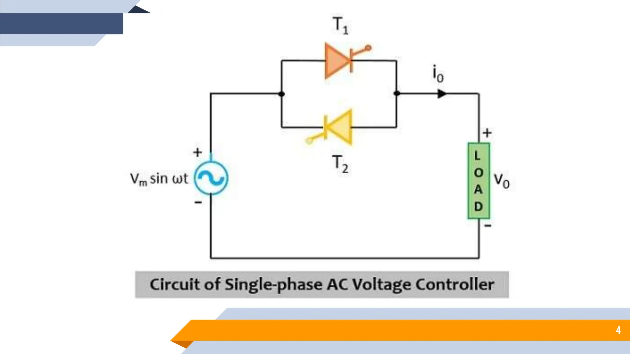
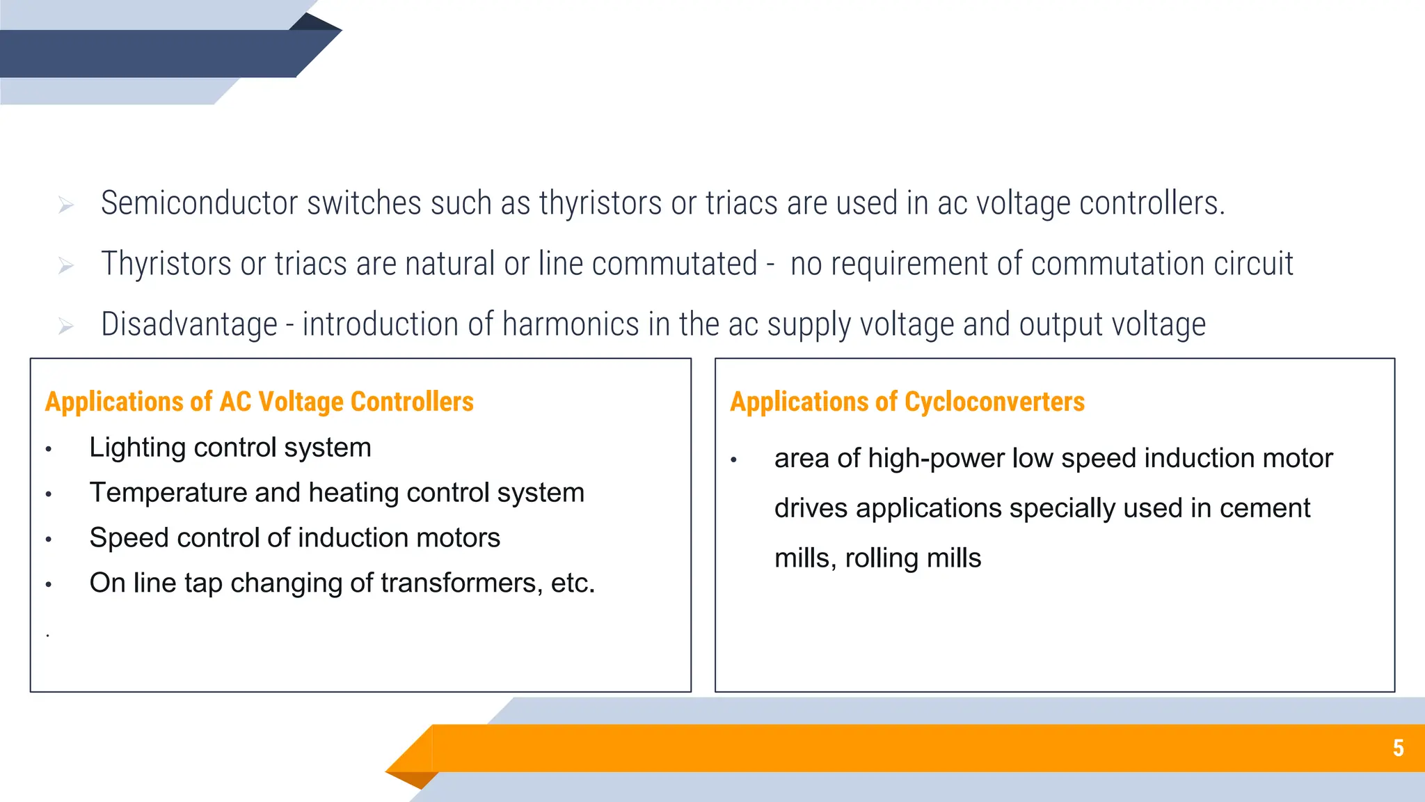


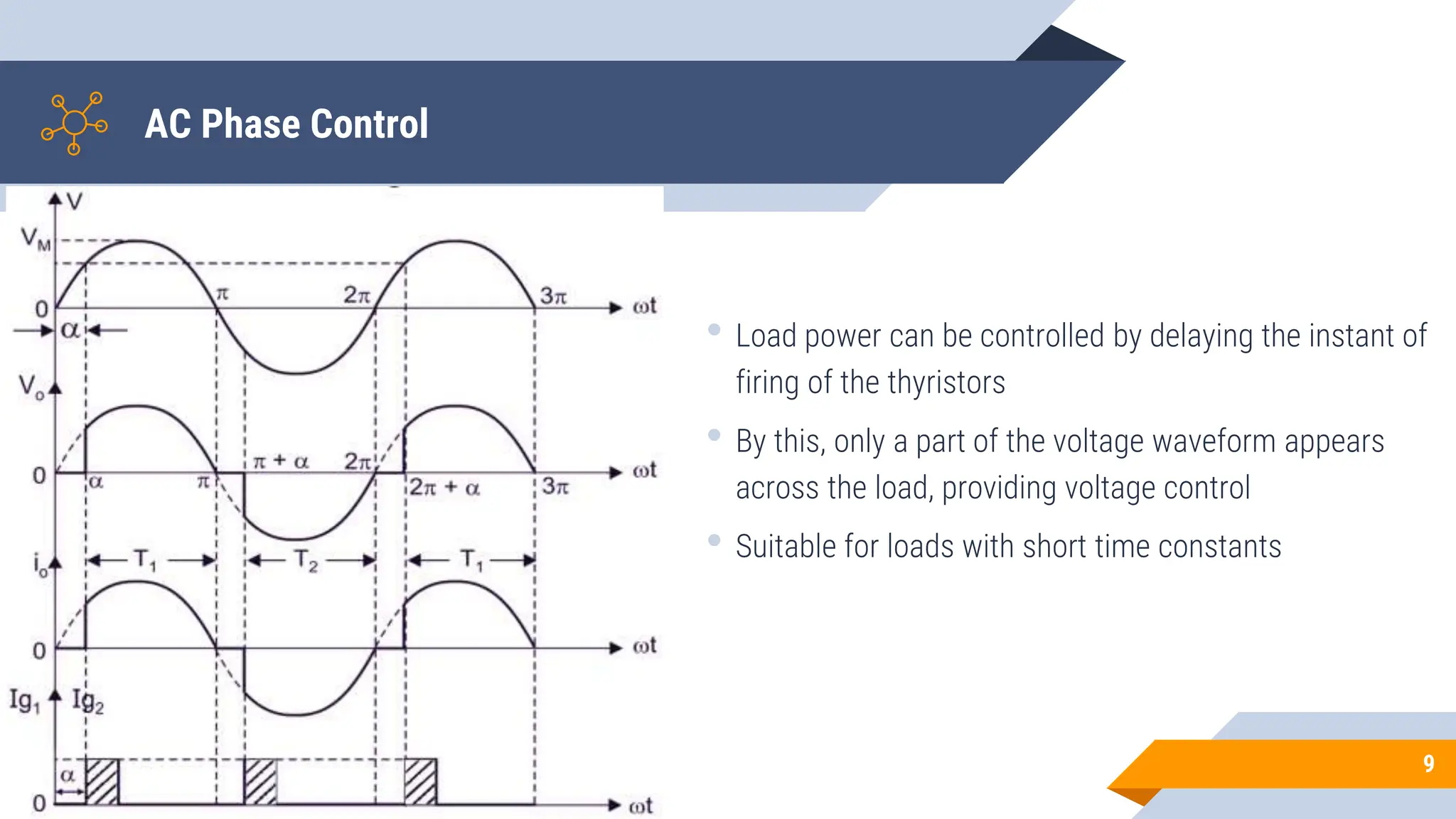


The document discusses AC to AC converters, particularly focusing on AC voltage controllers and cycloconverters that efficiently control power flow in electrical systems. It explains the use of silicon controlled rectifiers (SCRs), control strategies like integral cycle control and phase control, and the importance of power factor control in reducing reactive power. Various applications of cycloconverters, including high-power motor drives and their classifications based on input and output frequencies, are also highlighted.


