I. Transducers are devices that convert one form of energy into another. They may convert a physical quantity like pressure, temperature, or light intensity into an electrical signal.
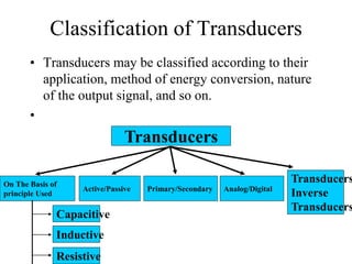
II. Transducers can be classified by their operating principle, type of output signal, energy conversion method, and more. Common types include resistive, capacitive, inductive, and piezoelectric transducers.
III. Examples of transducers include thermocouples and thermistors for temperature measurement, strain gauges and load cells for force/pressure measurement, and tachogenerators and optical sensors for speed measurement.