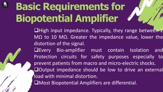
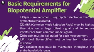
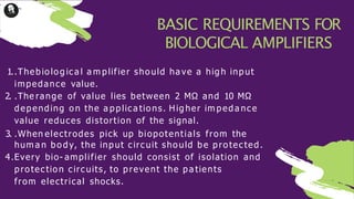
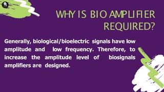
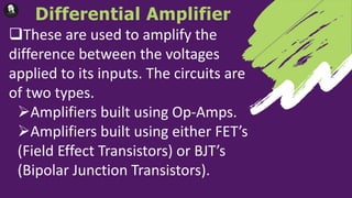
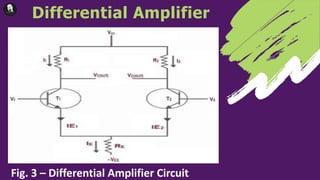
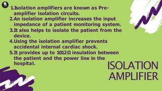
1. Biological amplifiers, also known as bio-amplifiers, are specifically designed to process low-amplitude bioelectric signals and increase their power.
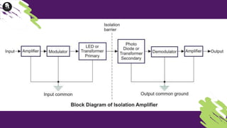
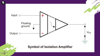
2. An ideal bio-amplifier must have high input impedance, isolation and protection circuits, high common mode rejection ratio, and maintain a constant gain across its bandwidth.
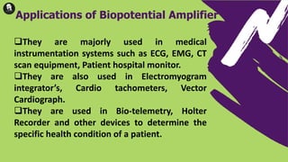
3. Bio-amplifiers are used to amplify biological signals measured from electrodes placed on the human body, such as electrocardiograms and electromyograms, before further analysis.