Download to read offline
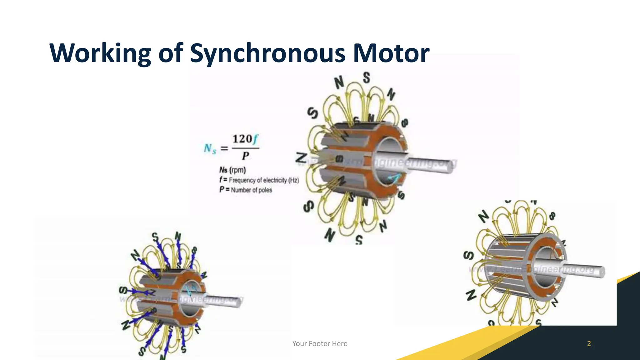
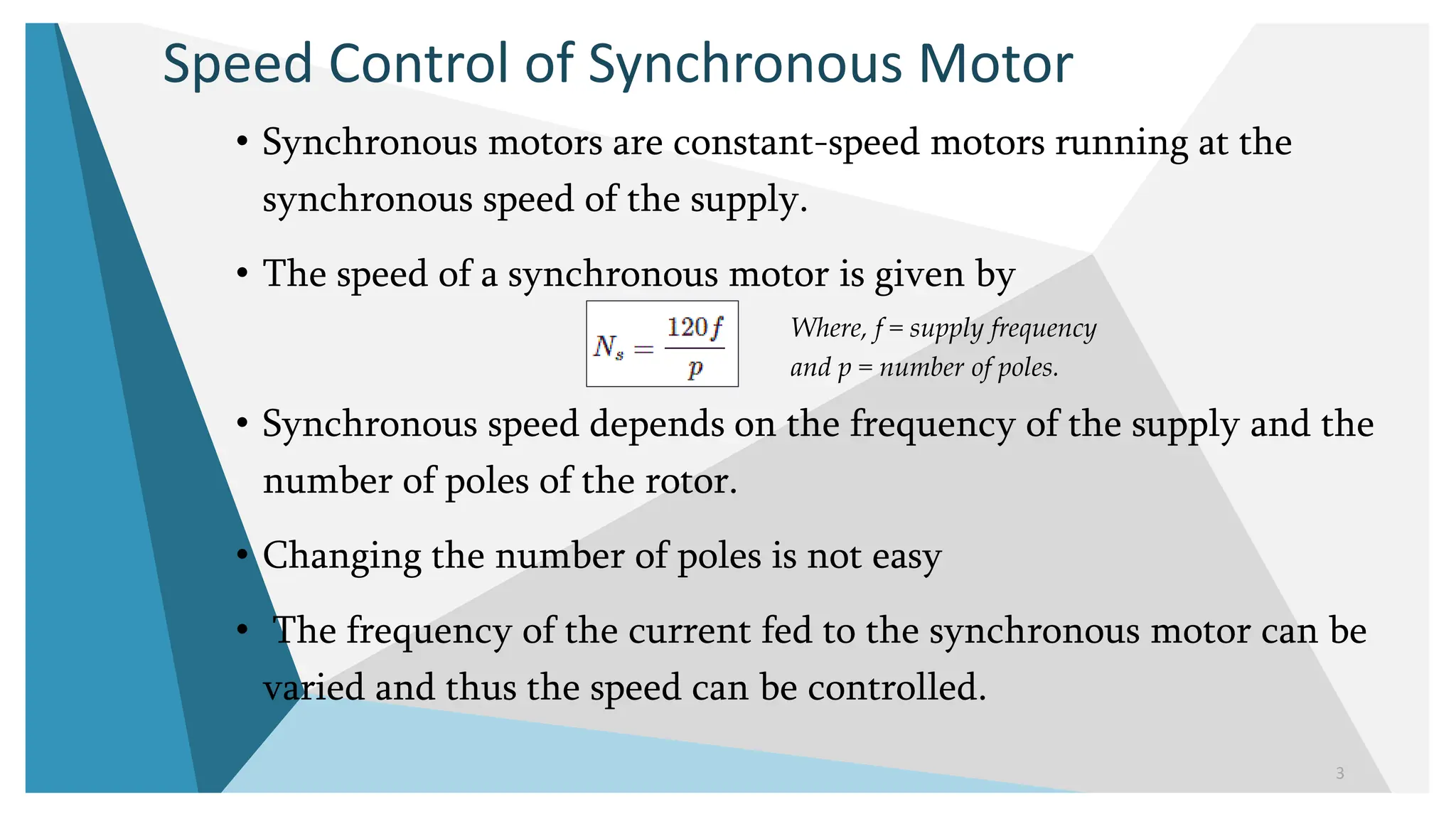
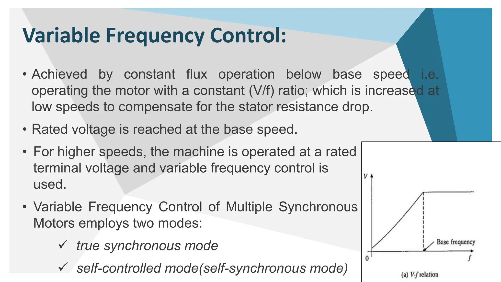
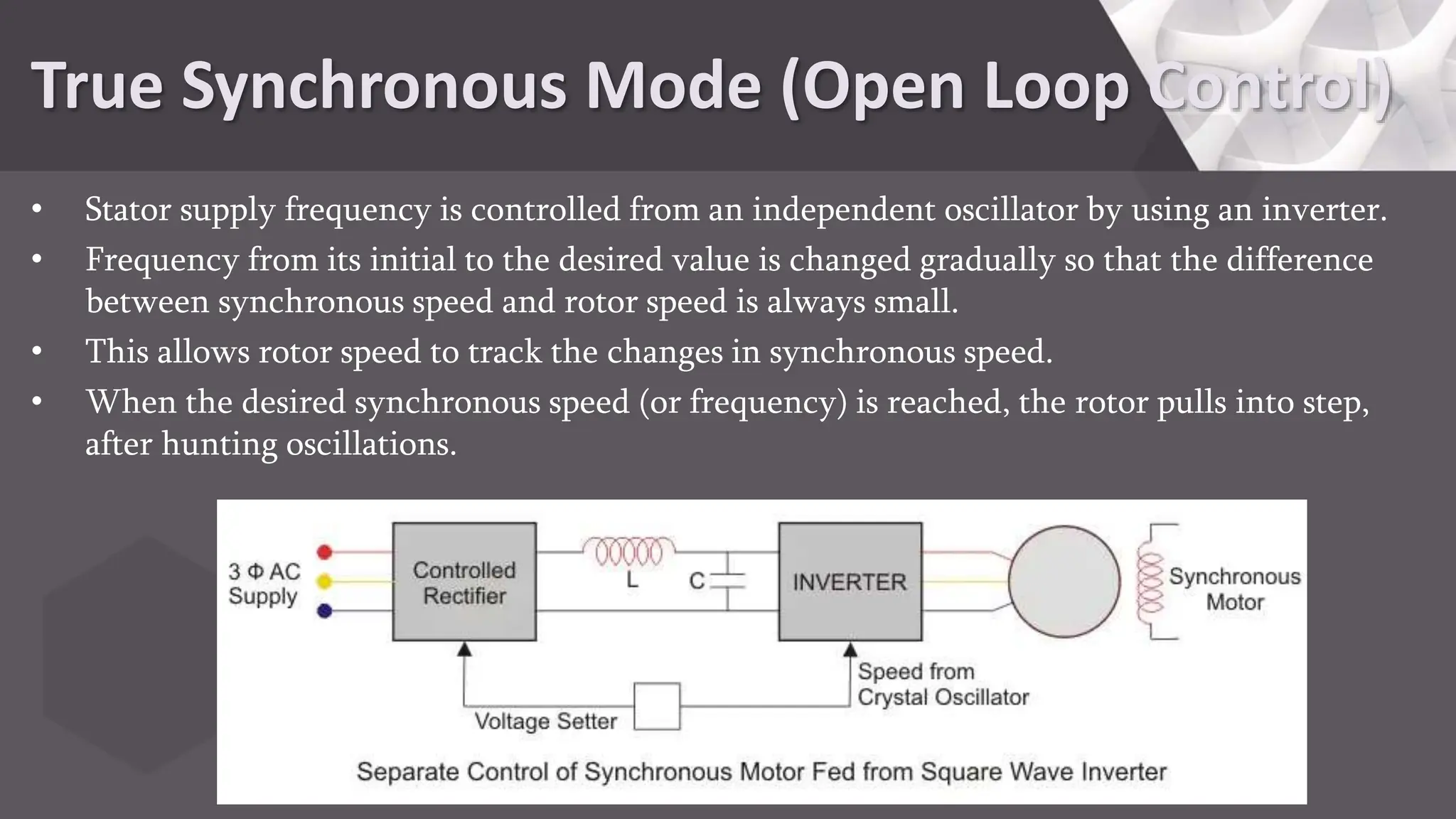
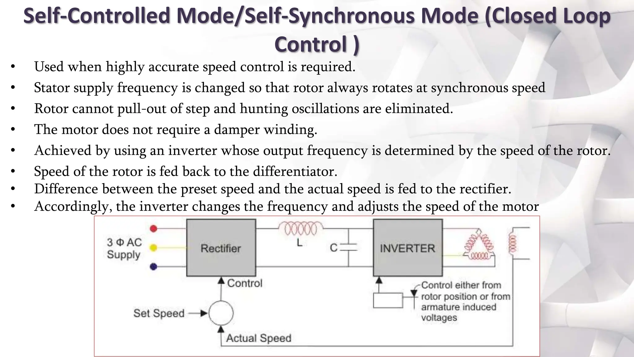
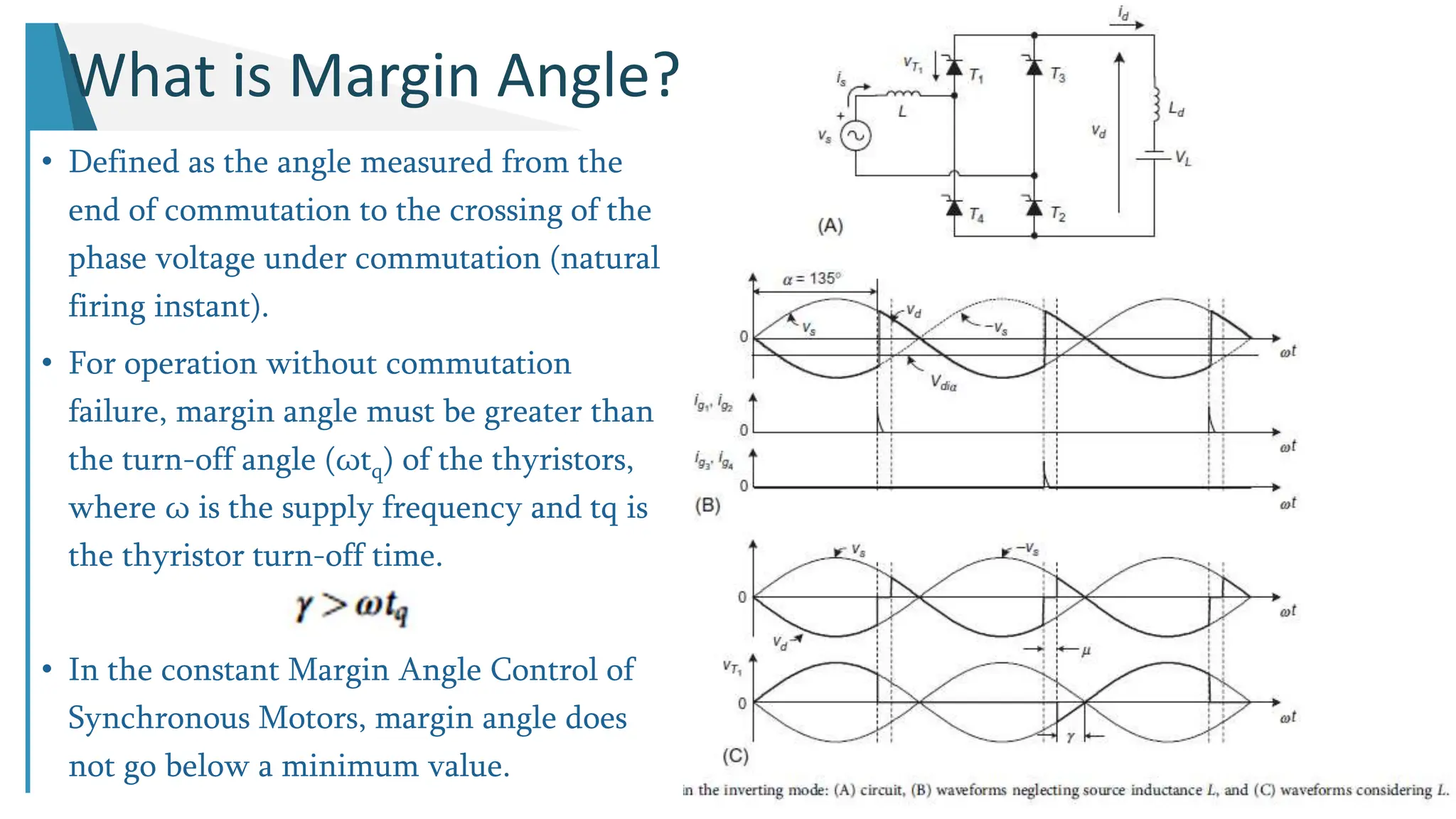
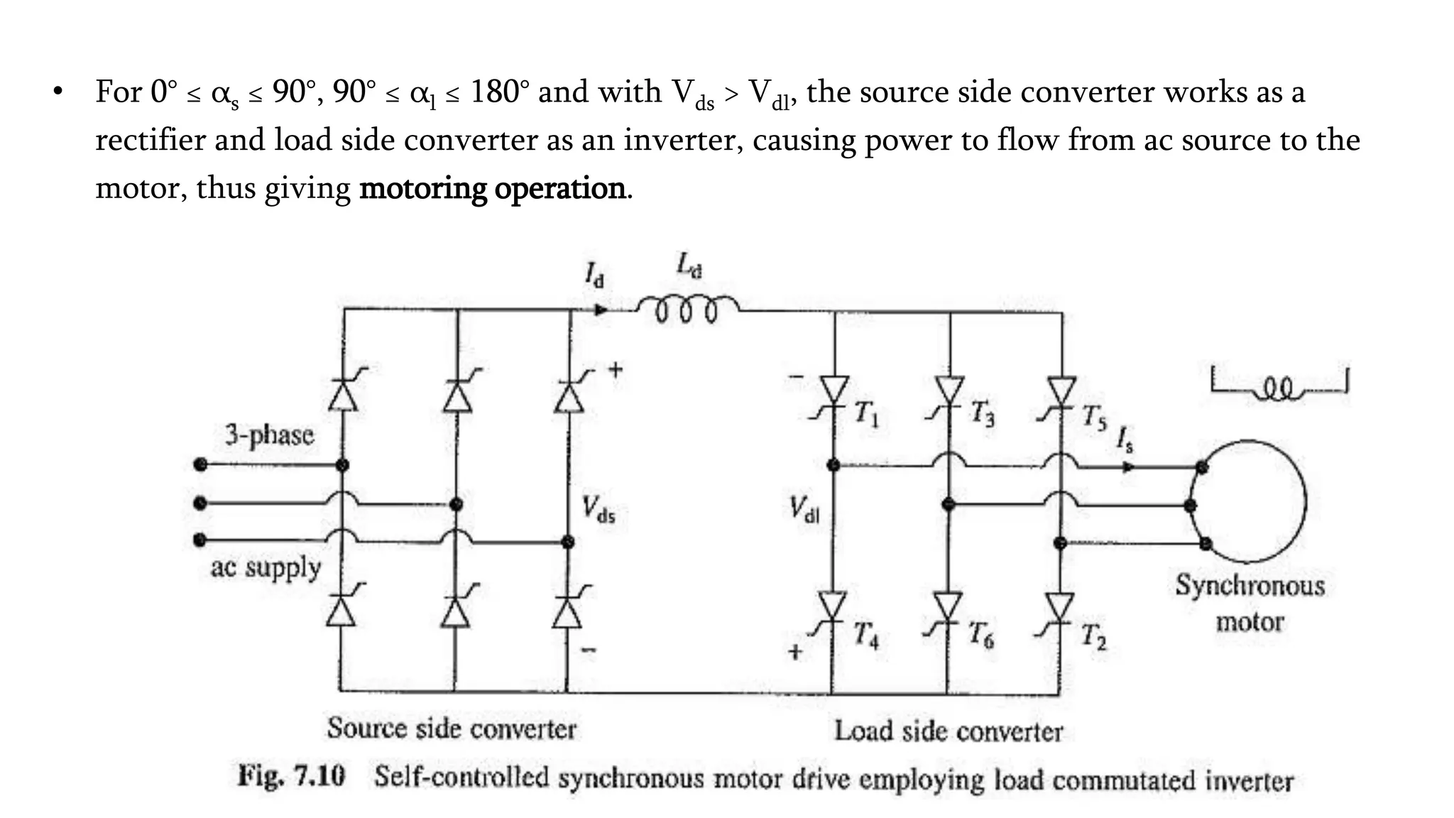
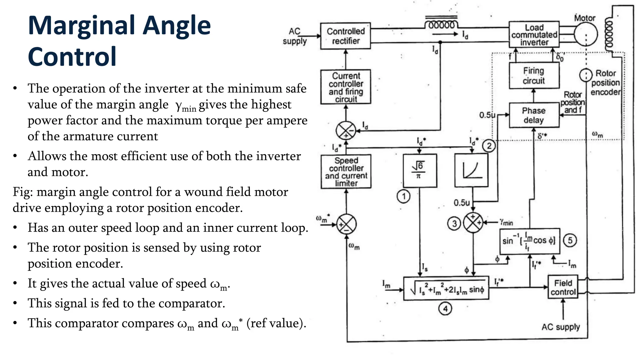
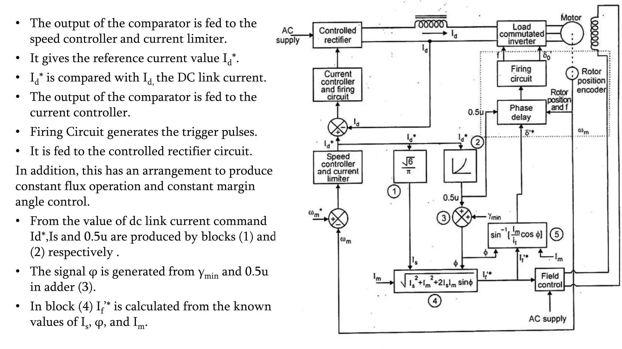
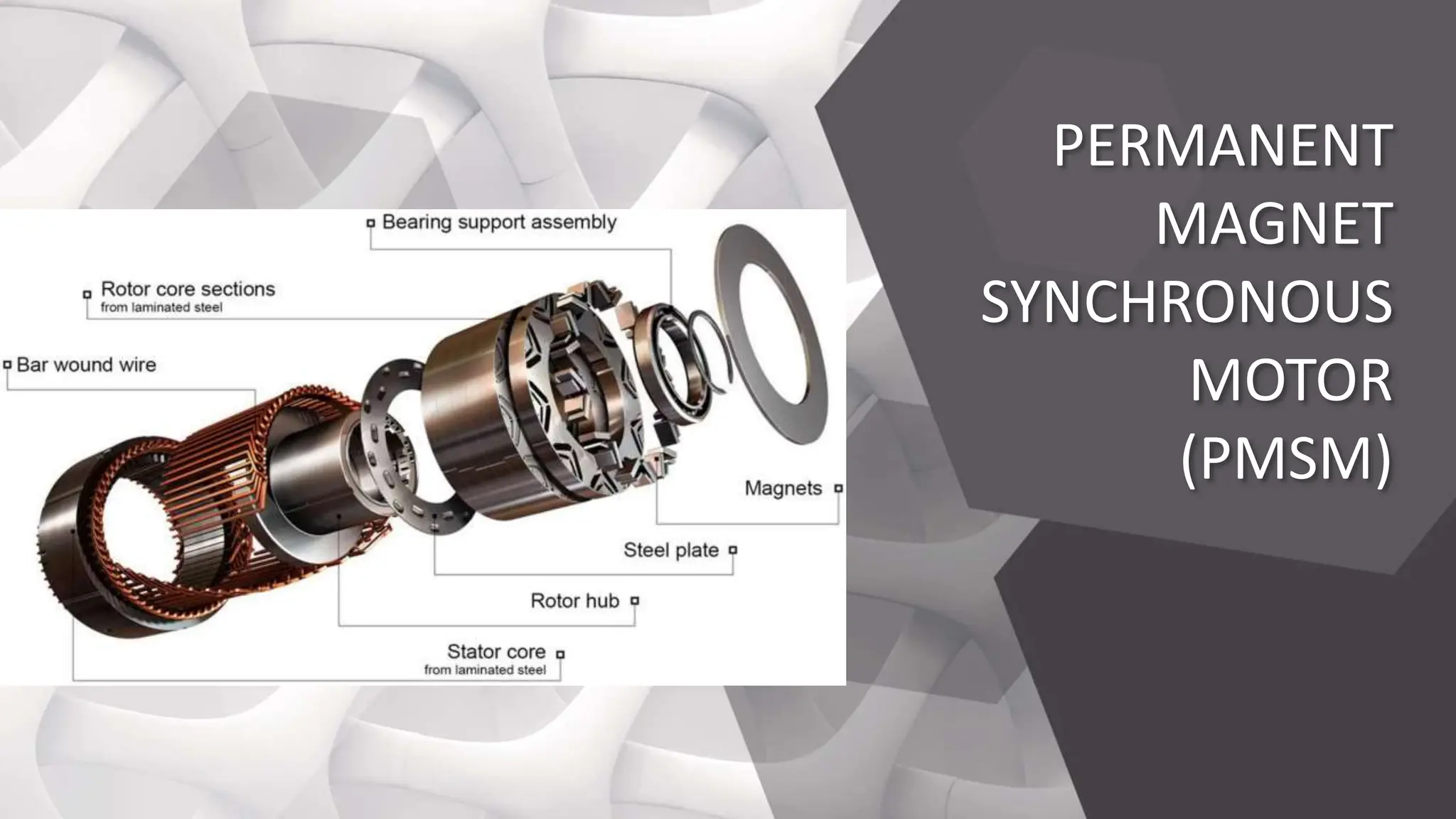
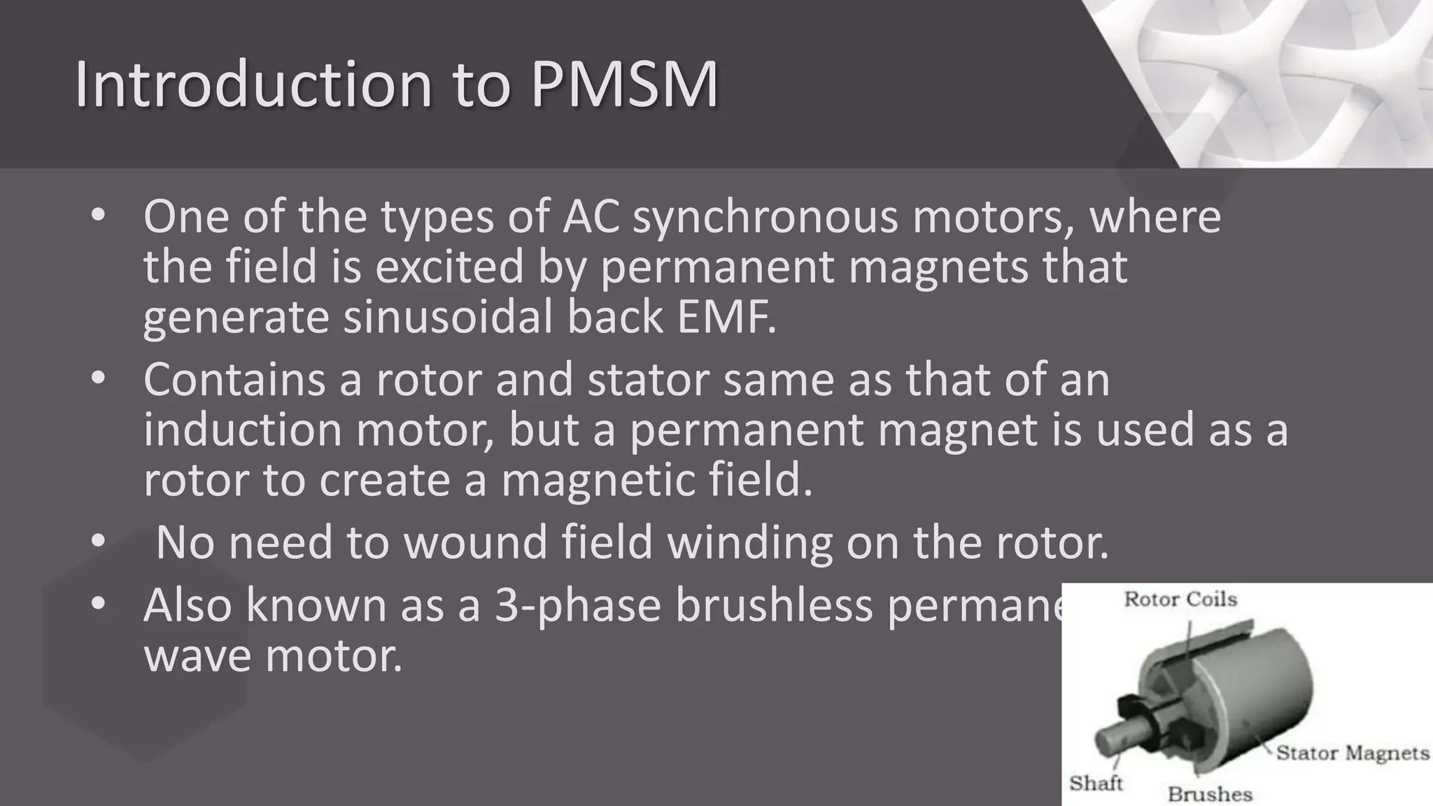
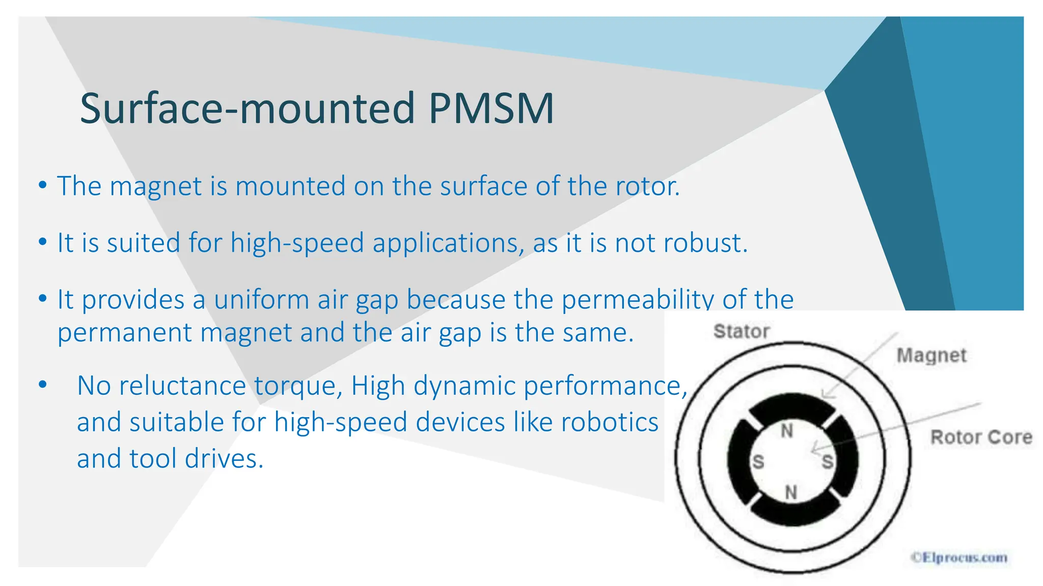
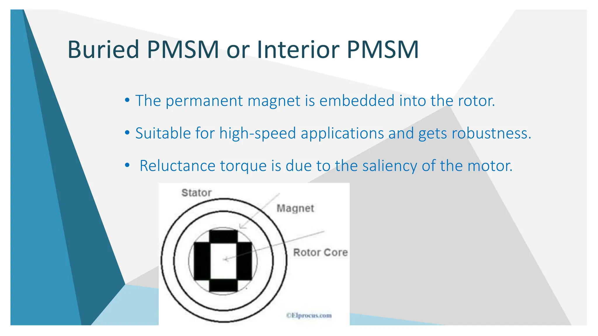
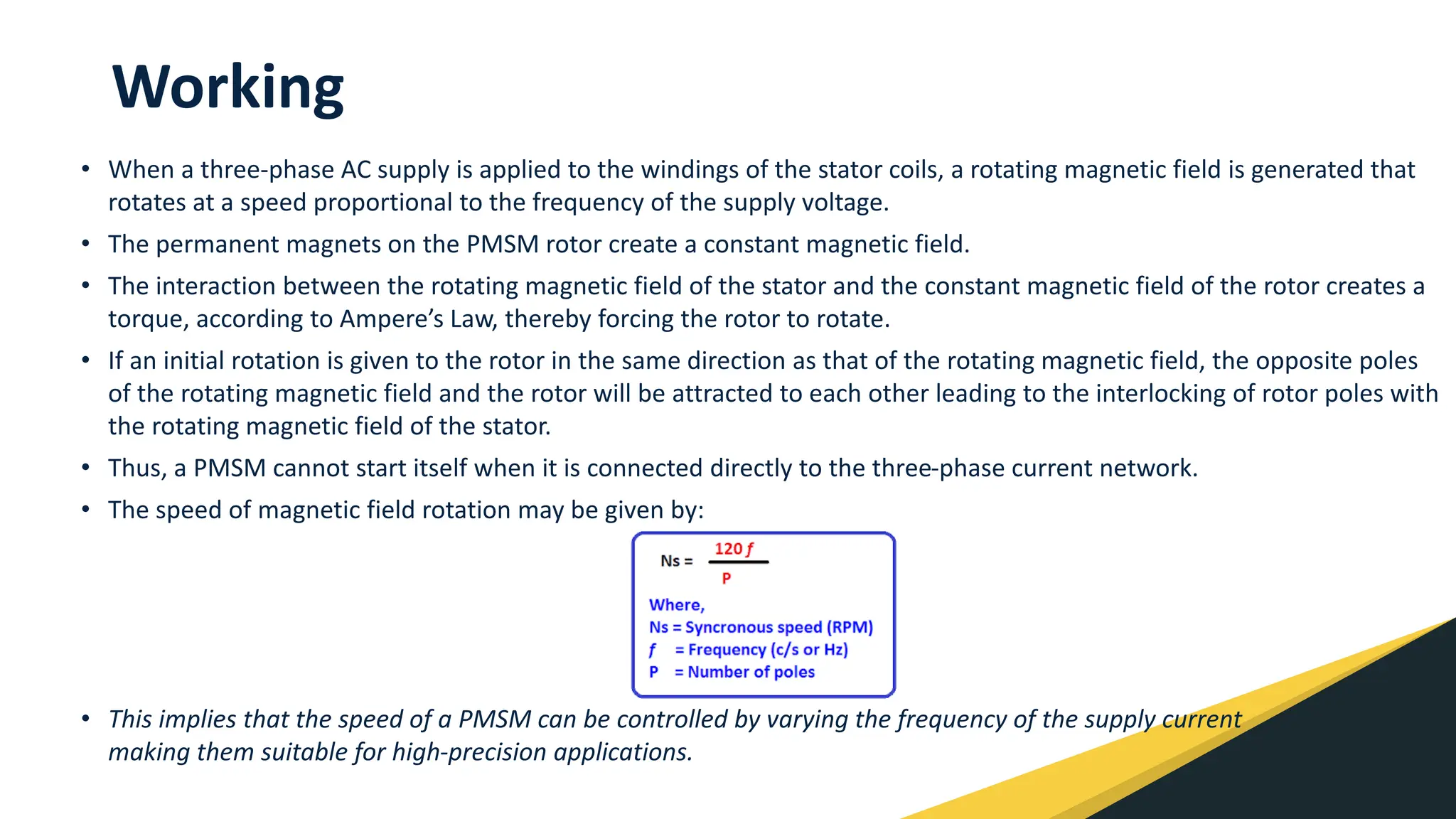


The document discusses the principles and operational methods of synchronous motor drives, highlighting speed control techniques such as variable frequency control and different operational modes (true synchronous mode and self-controlled mode). It details the use of converters in medium and high power applications, such as load commutated inverters and the significance of margin angle control. Additionally, it explores permanent magnet synchronous motors (PMSM), their construction, advantages, disadvantages, and various applications.