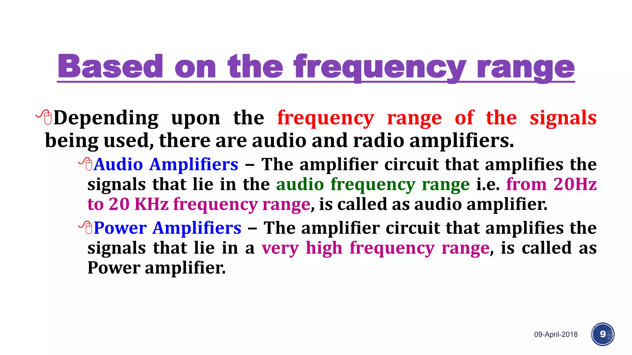
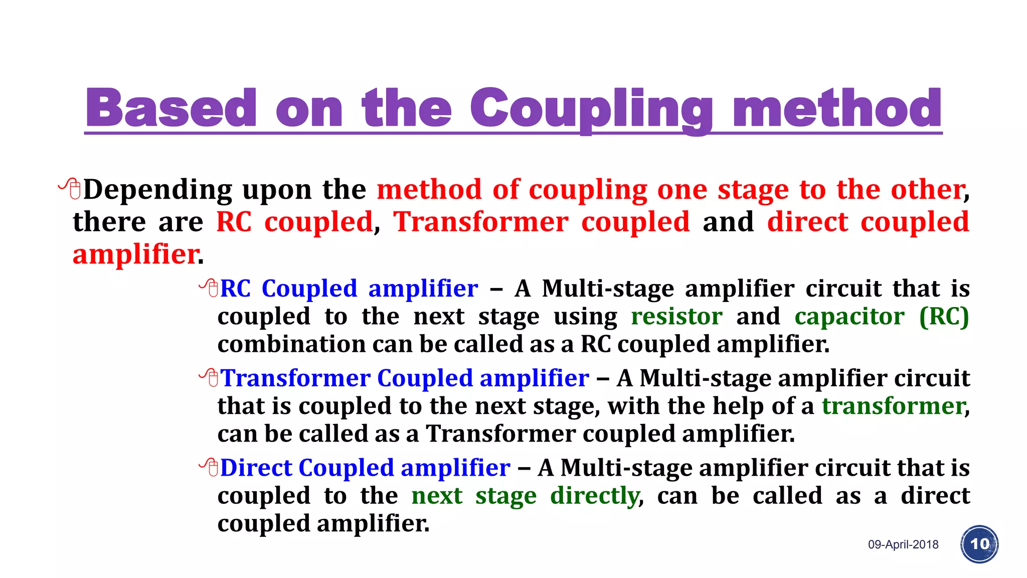
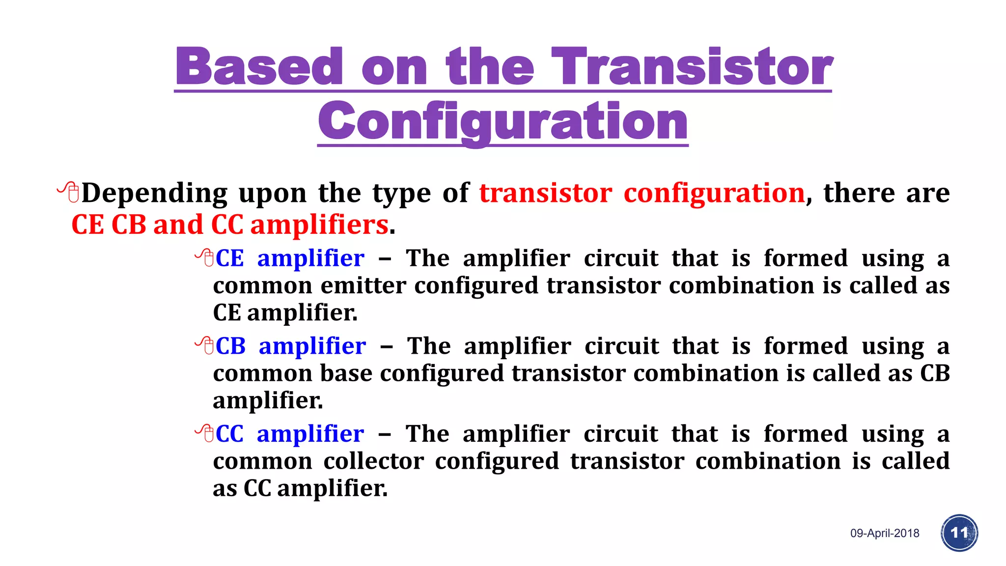
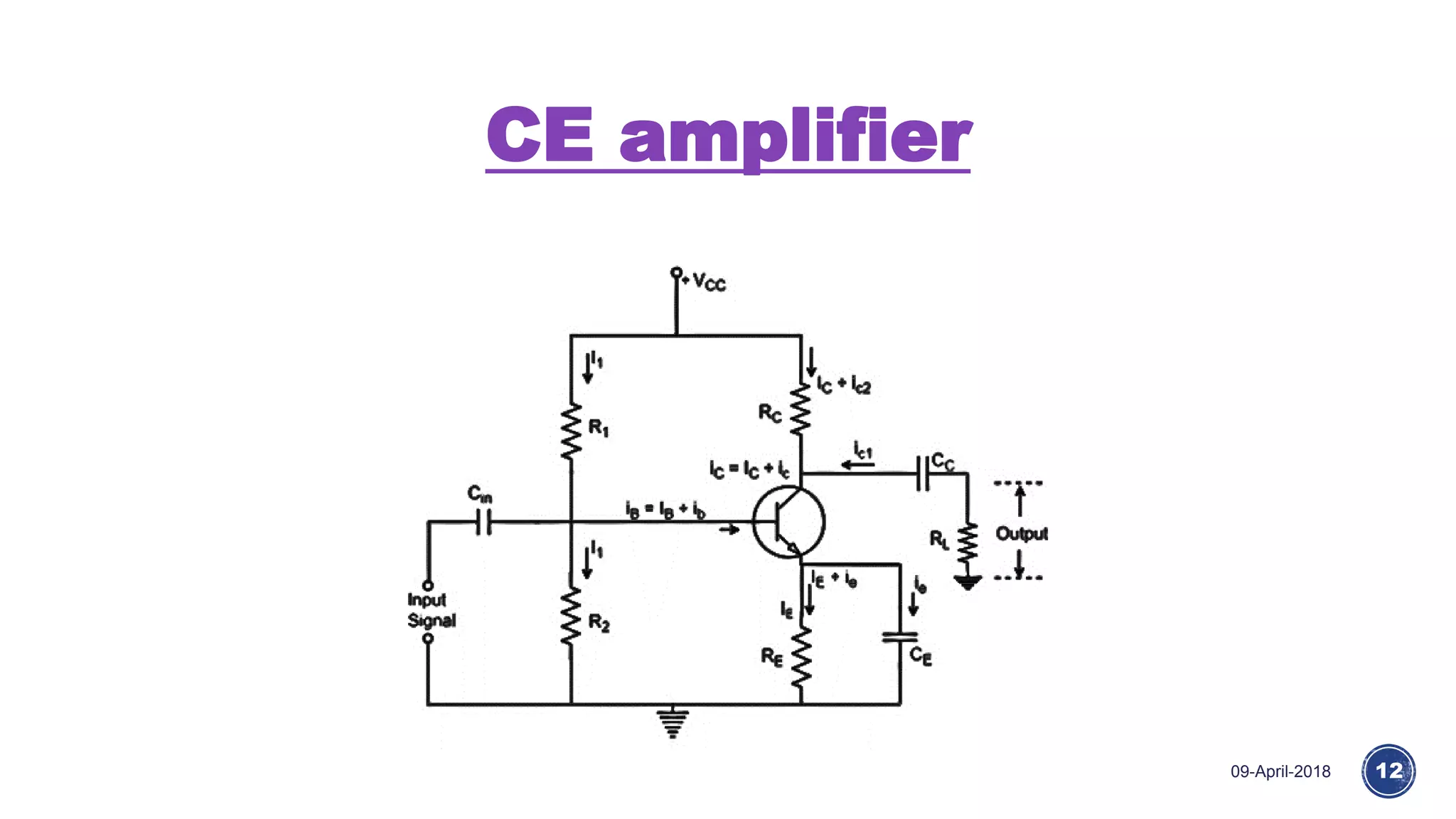
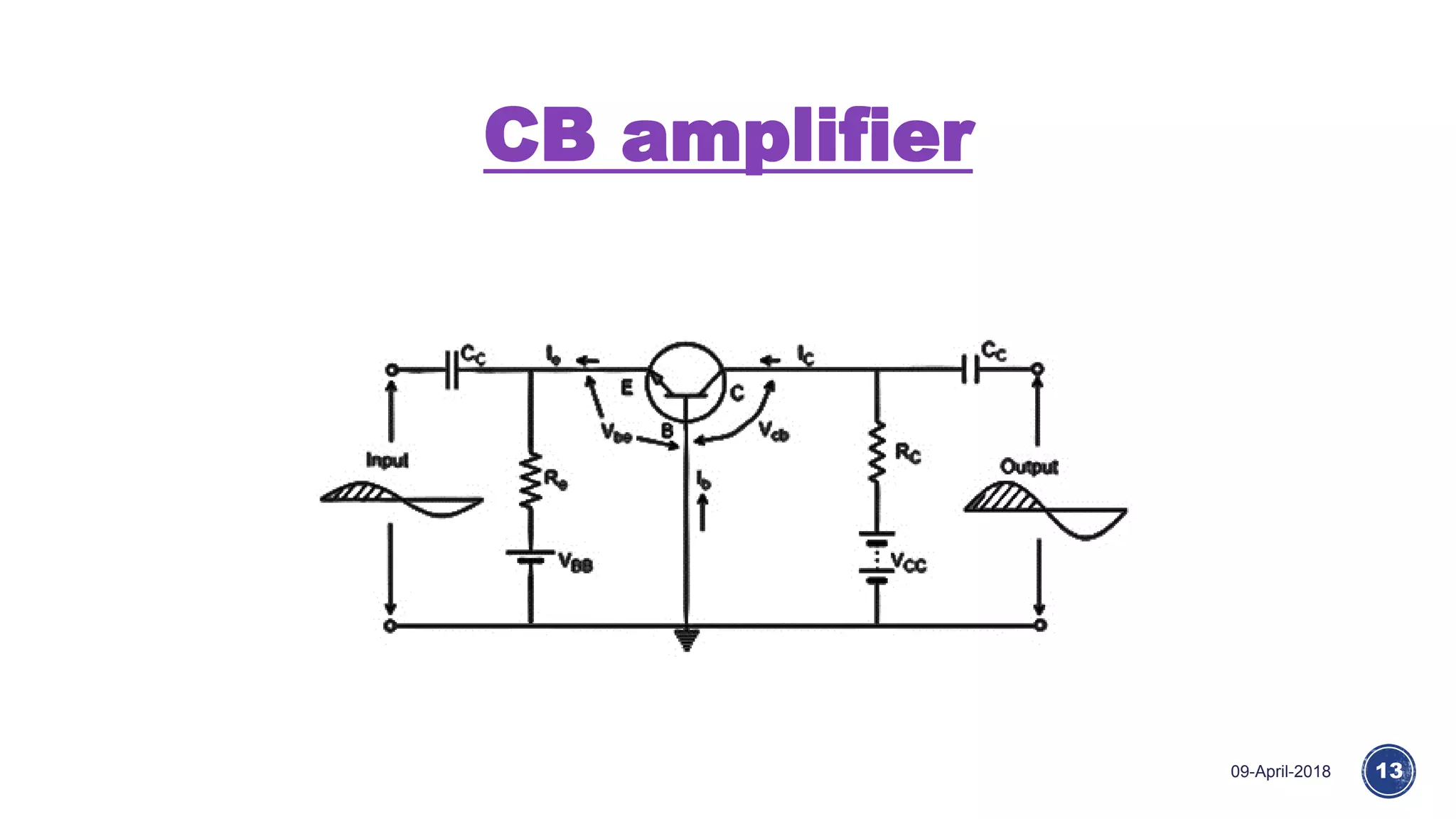
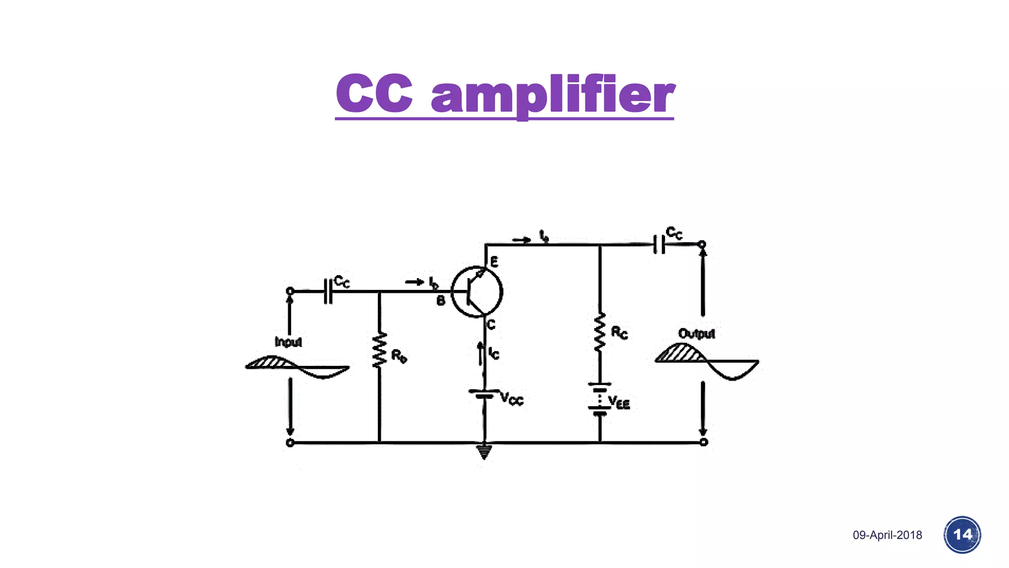
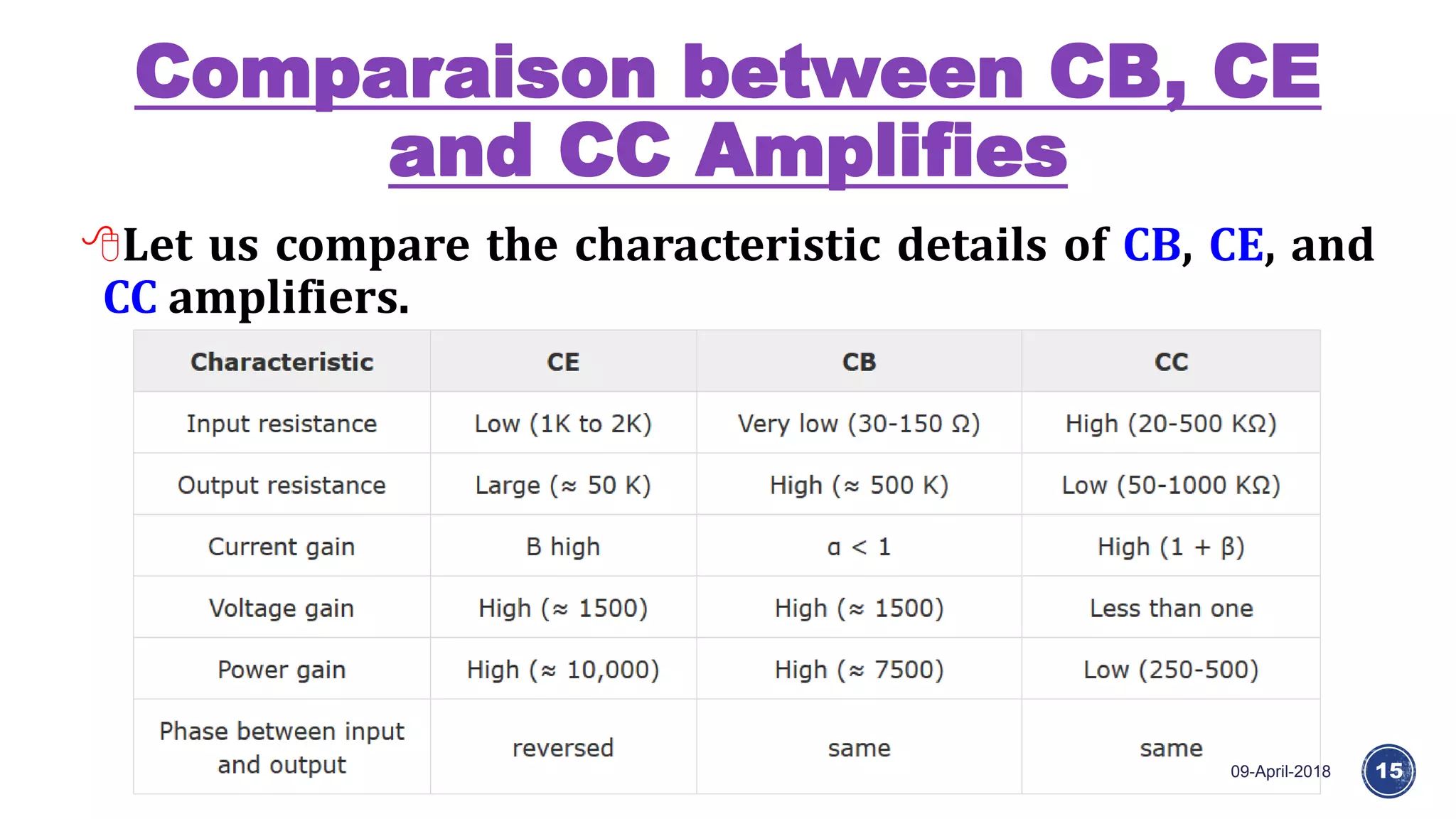
M. Raihan
Lecturer, Deparmaent of Computer
Science and Engineering, North
Western University, Bangladesh
Email: raihanbme@gmail.com
What is Amplifiers?
09-April-2018 2
An electronic signal contains some information which
cannot be utilized if doesn’t have proper strength.
The process of increasing the signal strength is called as
Amplification.
Almost all electronic equipment must include some means
for amplifying the signals.
We find the use of amplifiers in medical devices, scientific
equipment, automation, military tools, communication
devices, and even in household equipment.
Continue
09-April-2018 3
Amplification in practical applications is
done using Multi-stage amplifiers.
A number of single-stage amplifiers are
cascaded to form a Multi-stage amplifier.
Classification of Amplifiers
09-April-2018 4
Amplifiers are classified according to many
considerations :
Based on number of stages
Based on its output
Based on the input signals
Based on the frequency range
Based on the Coupling method
Based on the Transistor Configuration
Based on number of stages
09-April-2018 5
Depending upon the number of stages of Amplification,
there are Single-stage amplifiers and Multi-stage
amplifiers.
Single-stage Amplifiers − This has only one transistor
circuit, which is a single stage amplification.
Multi-stage Amplifiers − This has multiple transistor
circuit, which provides multi-stage amplification.
Single-stage Amplifier
09-April-2018 6
Based on its output
09-April-2018 7
Depending upon the parameter that is amplified at the
output, there are voltage and power amplifiers.
Voltage Amplifiers − The amplifier circuit that increases
the voltage level of the input signal, is called as Voltage
amplifier.
Power Amplifiers − The amplifier circuit that increases
the power level of the input signal, is called as Power
amplifier.
Based on the input signals
09-April-2018 8
Depending upon the magnitude of the input signal
applied, they can be categorized as small signal and large
signal amplifiers.
Small signal Amplifiers − When the input signal is so
weak so as to produce small fluctuations in the
collector current compared to its quiescent value, the
amplifier is known as Small signal amplifier.
Large signal amplifiers − When the fluctuations in
collector current are large i.e. beyond the linear
portion of the characteristics, the amplifier is known
as large signal amplifier.
Based on the frequency range
09-April-2018 9
Depending upon the frequency range of the signals
being used, there are audio and radio amplifiers.
Audio Amplifiers − The amplifier circuit that amplifies the
signals that lie in the audio frequency range i.e. from 20Hz
to 20 KHz frequency range, is called as audio amplifier.
Power Amplifiers − The amplifier circuit that amplifies the
signals that lie in a very high frequency range, is called as
Power amplifier.
Based on the Coupling method
09-April-2018 10
Depending upon the method of coupling one stage to the other,
there are RC coupled, Transformer coupled and direct coupled
amplifier.
RC Coupled amplifier − A Multi-stage amplifier circuit that is
coupled to the next stage using resistor and capacitor (RC)
combination can be called as a RC coupled amplifier.
Transformer Coupled amplifier − A Multi-stage amplifier circuit
that is coupled to the next stage, with the help of a transformer,
can be called as a Transformer coupled amplifier.
Direct Coupled amplifier − A Multi-stage amplifier circuit that is
coupled to the next stage directly, can be called as a direct
coupled amplifier.
Based on the Transistor
Configuration
09-April-2018 11
Depending upon the type of transistor configuration, there are
CE CB and CC amplifiers.
CE amplifier − The amplifier circuit that is formed using a
common emitter configured transistor combination is called as
CE amplifier.
CB amplifier − The amplifier circuit that is formed using a
common base configured transistor combination is called as CB
amplifier.
CC amplifier − The amplifier circuit that is formed using a
common collector configured transistor combination is called
as CC amplifier.
CE amplifier
09-April-2018 12
CB amplifier
09-April-2018 13
CC amplifier
09-April-2018 14
Comparaison between CB, CE
and CC Amplifies
09-April-2018 15
Let us compare the characteristic details of CB, CE, and
CC amplifiers.
Noise in Amplifier
09-April-2018 16
An Amplifier, while amplifying just increases the
strength of its input signal whether it contains
information or some noise along with information.
This noise or some disturbance is introduced in the
amplifiers because of their strong tendency to introduce
hum due to sudden temperature changes or stray electric
and magnetic fields.
What is Noise?
09-April-2018 17
Noise is an unwanted signal which
interferes with the original
message signal and corrupts the
parameters of the message signal.
This alteration in the
communication process, makes the
message to get altered after
reaching.
It is most likely to be entered at
the channel or the receiver.
Signal to Noise Ratio (SNR)
09-April-2018 18
The ratio of the information signal present in the
received signal to the noise present is called as Signal to
Noise ratio.
This ratio has to be higher for a system so that it
produces pure information signal unaffected by the
unwanted noise.
SNR = Psignal/Pnoise
SNRdb=10log10(Psignal/Pnoise)
Biopotential Amplifiers
09-April-2018 19
An electrophysiological device, a variation of the
instrumentation amplifier, used to gather and increase
the signal integrity of physiologic electrical activity for
output to various sources.
It may be an independent unit, or integrated into the
electrodes.
Amplifiers that have been designed specifically for
this type of processing of biopotentials are known as
biopotential amplifiers.
Typical bio-amplifier requirements
09-April-2018 20
High input impedance - greater than 10 M ohms.
Safety: protect the organism being studied.
careful design to prevent macro and microshocks.
isolation and protection circuitry to limit the current
through the electrode to safe level.
Output impedance of the amplifier.
should be low to drive any external load with minimal distortion.
Gain greater than 1000
biopotentials are typically less than a millivolt
Continue
09-April-2018 21
Most biopotential amplifiers are differential
signals are recorded using a bipolar electrodes which
are symmetrically located
High common mode rejection ratio
biopotentials ride on a large offset signals
Rapid calibration of the amplifier in laboratory conditions
Adjustable gains
often the change in scale is automatic
therefore calibration of the equipment is very
important
Voltage and Frequency
Range for Biopotentials
09-April-2018 22
Voltage and frequency ranges of
some common biopotential
signals; dc potentials include
intracellular voltages as well as
voltages measured from several
points on the body. EOG is the
electrooculogram, EEG is the
electroencephalogram, ECG is
the electrocardiogram, EMG is
the electromyogram, and AAP is
the axon action potential.
Electrocardiograph Amplifiers
09-April-2018 23
Beating heart generates electric signal
monitored to understand heart
functions
Measurements are functions of
location at which the signal is
detected
time-dependence of the signal
amplitude
Different pairs of electrodes at different
locations yield different measurements
hence placement is standardized
Continue
09-April-2018 24
Electrical model of heart
Electric dipole located in a partially
conducting medium (thorax)
Dipole represented as a cardiac vector
M
M is the dipole moment
During the cardiac cycle
magnitude and direction of the
dipole vector will vary
Electric potentials appears throughout
the body and on its surface
va1 = M.a1, va1 = |𝑴| cos𝜽
Electrocardiograph Leads
09-April-2018 25
In clinical electrocardiography
More than one lead must be recorded to describe the heart's electric
activity fully.
Several leads are taken in the frontal plane and the transverse plane.
frontal plane: parallel to the back when lying.
transverse plane: parallel to the ground when standing.
Frontal plane lead placement
Called Eindhoven’s triangle
Additional leads
Unipolar measurements
potential measured at electrodes w.r.t. A reference; average of the 2
electrodes
Wilson central terminal
three limb electrodes connected through equal-valued resistors to a
common node
Augmented leads
some nodes disconnected
increase the amplitude of measurement using
Functional blocks of
Electrocardiograph
09-April-2018 26
Problems in ECG Measurement
09-April-2018 27
Frequency distortion
If filter specification does not match the frequency content of
biopotential
Then the result is high and low frequency distortion
Saturation or cutoff distortion
High electrode offset voltage or improperly calibrated
amplifiers can drive the amplifier into saturation
Then the peaks of QRS waveforms are cut off
Ground loops
If two monitoring instruments are placed at disjoint ground
points then small current could flow through the patient s ’s
body.
Continue
09-April-2018 28
Electric/magnetic field
coupling
Open lead wires (floating
connections) pick up EMI
Long leads produce loop that
picks up EMI (induces loop
current)
Interference from power lines
(common mode interference)
can couple onto ECG signal
Interference Reduction Techniques
09-April-2018 29
Common-mode voltages can be responsible for much of the interference in
biopotential amplifiers.
Solution 1:
Amplifier with a very high common-mode rejection
Solution 2:
Eliminate the source of interference
Ways to eliminate interference
Use shielding techniques
Electrostatic shielding: Place a grounded conducting plane between the
source of the electric field and the measurement system
Very important for EEG measurement
Magnetic shield
Use high permeability materials (sheet steel)
Use twisted cables to reduce magnetic flux, reduce lead loop area.
Differential Amplifier
09-April-2018 30
A differential amplifier is a type of electronic
amplifier that amplifies the difference between two
input voltages but suppresses any voltage common
to the two inputs.
Differential amplifier symbol: The inverting and
non-inverting inputs are distinguished by "−" and
"+" symbols (respectively) placed in the amplifier
triangle. Vs+ and Vs− are the power supply voltages;
they are often omitted from the diagram for
simplicity but must be present in the actual circuit.
Continue
09-April-2018 31
Instrumentation Amplifier
09-April-2018 32
Continue
09-April-2018 33
EMG Amplifier
09-April-2018 34
Electromyography signals range in frequency from 25 Hz to
several kilohertz.
Signal amplitudes range from 100 µV to 90 mV, depending on the
type of signal and electrodes used.
If skin-surface electrodes are used to detect the EMG, the levels
of signals are generally low, having peak amplitudes of the order
of 0.1 to 1 mV.
Electrode impedance is relatively low, ranging from about 200 to
5000 Ω, depending on the type of electrode, the electrode–
electrolyte interface, and the frequency at which the impedance
is determined.
Thank You
09-April-2018 35

Amplifiers and biopotential amplifiers new

  • 1.
    M. Raihan Lecturer, Deparmaentof Computer Science and Engineering, North Western University, Bangladesh Email: raihanbme@gmail.com
  • 2.
    What is Amplifiers? 09-April-20182 An electronic signal contains some information which cannot be utilized if doesn’t have proper strength. The process of increasing the signal strength is called as Amplification. Almost all electronic equipment must include some means for amplifying the signals. We find the use of amplifiers in medical devices, scientific equipment, automation, military tools, communication devices, and even in household equipment.
  • 3.
    Continue 09-April-2018 3 Amplification inpractical applications is done using Multi-stage amplifiers. A number of single-stage amplifiers are cascaded to form a Multi-stage amplifier.
  • 4.
    Classification of Amplifiers 09-April-20184 Amplifiers are classified according to many considerations : Based on number of stages Based on its output Based on the input signals Based on the frequency range Based on the Coupling method Based on the Transistor Configuration
  • 5.
    Based on numberof stages 09-April-2018 5 Depending upon the number of stages of Amplification, there are Single-stage amplifiers and Multi-stage amplifiers. Single-stage Amplifiers − This has only one transistor circuit, which is a single stage amplification. Multi-stage Amplifiers − This has multiple transistor circuit, which provides multi-stage amplification.
  • 6.
  • 7.
    Based on itsoutput 09-April-2018 7 Depending upon the parameter that is amplified at the output, there are voltage and power amplifiers. Voltage Amplifiers − The amplifier circuit that increases the voltage level of the input signal, is called as Voltage amplifier. Power Amplifiers − The amplifier circuit that increases the power level of the input signal, is called as Power amplifier.
  • 8.
    Based on theinput signals 09-April-2018 8 Depending upon the magnitude of the input signal applied, they can be categorized as small signal and large signal amplifiers. Small signal Amplifiers − When the input signal is so weak so as to produce small fluctuations in the collector current compared to its quiescent value, the amplifier is known as Small signal amplifier. Large signal amplifiers − When the fluctuations in collector current are large i.e. beyond the linear portion of the characteristics, the amplifier is known as large signal amplifier.
  • 9.
    Based on thefrequency range 09-April-2018 9 Depending upon the frequency range of the signals being used, there are audio and radio amplifiers. Audio Amplifiers − The amplifier circuit that amplifies the signals that lie in the audio frequency range i.e. from 20Hz to 20 KHz frequency range, is called as audio amplifier. Power Amplifiers − The amplifier circuit that amplifies the signals that lie in a very high frequency range, is called as Power amplifier.
  • 10.
    Based on theCoupling method 09-April-2018 10 Depending upon the method of coupling one stage to the other, there are RC coupled, Transformer coupled and direct coupled amplifier. RC Coupled amplifier − A Multi-stage amplifier circuit that is coupled to the next stage using resistor and capacitor (RC) combination can be called as a RC coupled amplifier. Transformer Coupled amplifier − A Multi-stage amplifier circuit that is coupled to the next stage, with the help of a transformer, can be called as a Transformer coupled amplifier. Direct Coupled amplifier − A Multi-stage amplifier circuit that is coupled to the next stage directly, can be called as a direct coupled amplifier.
  • 11.
    Based on theTransistor Configuration 09-April-2018 11 Depending upon the type of transistor configuration, there are CE CB and CC amplifiers. CE amplifier − The amplifier circuit that is formed using a common emitter configured transistor combination is called as CE amplifier. CB amplifier − The amplifier circuit that is formed using a common base configured transistor combination is called as CB amplifier. CC amplifier − The amplifier circuit that is formed using a common collector configured transistor combination is called as CC amplifier.
  • 12.
  • 13.
  • 14.
  • 15.
    Comparaison between CB,CE and CC Amplifies 09-April-2018 15 Let us compare the characteristic details of CB, CE, and CC amplifiers.
  • 16.
    Noise in Amplifier 09-April-201816 An Amplifier, while amplifying just increases the strength of its input signal whether it contains information or some noise along with information. This noise or some disturbance is introduced in the amplifiers because of their strong tendency to introduce hum due to sudden temperature changes or stray electric and magnetic fields.
  • 17.
    What is Noise? 09-April-201817 Noise is an unwanted signal which interferes with the original message signal and corrupts the parameters of the message signal. This alteration in the communication process, makes the message to get altered after reaching. It is most likely to be entered at the channel or the receiver.
  • 18.
    Signal to NoiseRatio (SNR) 09-April-2018 18 The ratio of the information signal present in the received signal to the noise present is called as Signal to Noise ratio. This ratio has to be higher for a system so that it produces pure information signal unaffected by the unwanted noise. SNR = Psignal/Pnoise SNRdb=10log10(Psignal/Pnoise)
  • 19.
    Biopotential Amplifiers 09-April-2018 19 Anelectrophysiological device, a variation of the instrumentation amplifier, used to gather and increase the signal integrity of physiologic electrical activity for output to various sources. It may be an independent unit, or integrated into the electrodes. Amplifiers that have been designed specifically for this type of processing of biopotentials are known as biopotential amplifiers.
  • 20.
    Typical bio-amplifier requirements 09-April-201820 High input impedance - greater than 10 M ohms. Safety: protect the organism being studied. careful design to prevent macro and microshocks. isolation and protection circuitry to limit the current through the electrode to safe level. Output impedance of the amplifier. should be low to drive any external load with minimal distortion. Gain greater than 1000 biopotentials are typically less than a millivolt
  • 21.
    Continue 09-April-2018 21 Most biopotentialamplifiers are differential signals are recorded using a bipolar electrodes which are symmetrically located High common mode rejection ratio biopotentials ride on a large offset signals Rapid calibration of the amplifier in laboratory conditions Adjustable gains often the change in scale is automatic therefore calibration of the equipment is very important
  • 22.
    Voltage and Frequency Rangefor Biopotentials 09-April-2018 22 Voltage and frequency ranges of some common biopotential signals; dc potentials include intracellular voltages as well as voltages measured from several points on the body. EOG is the electrooculogram, EEG is the electroencephalogram, ECG is the electrocardiogram, EMG is the electromyogram, and AAP is the axon action potential.
  • 23.
    Electrocardiograph Amplifiers 09-April-2018 23 Beatingheart generates electric signal monitored to understand heart functions Measurements are functions of location at which the signal is detected time-dependence of the signal amplitude Different pairs of electrodes at different locations yield different measurements hence placement is standardized
  • 24.
    Continue 09-April-2018 24 Electrical modelof heart Electric dipole located in a partially conducting medium (thorax) Dipole represented as a cardiac vector M M is the dipole moment During the cardiac cycle magnitude and direction of the dipole vector will vary Electric potentials appears throughout the body and on its surface va1 = M.a1, va1 = |𝑴| cos𝜽
  • 25.
    Electrocardiograph Leads 09-April-2018 25 Inclinical electrocardiography More than one lead must be recorded to describe the heart's electric activity fully. Several leads are taken in the frontal plane and the transverse plane. frontal plane: parallel to the back when lying. transverse plane: parallel to the ground when standing. Frontal plane lead placement Called Eindhoven’s triangle Additional leads Unipolar measurements potential measured at electrodes w.r.t. A reference; average of the 2 electrodes Wilson central terminal three limb electrodes connected through equal-valued resistors to a common node Augmented leads some nodes disconnected increase the amplitude of measurement using
  • 26.
  • 27.
    Problems in ECGMeasurement 09-April-2018 27 Frequency distortion If filter specification does not match the frequency content of biopotential Then the result is high and low frequency distortion Saturation or cutoff distortion High electrode offset voltage or improperly calibrated amplifiers can drive the amplifier into saturation Then the peaks of QRS waveforms are cut off Ground loops If two monitoring instruments are placed at disjoint ground points then small current could flow through the patient s ’s body.
  • 28.
    Continue 09-April-2018 28 Electric/magnetic field coupling Openlead wires (floating connections) pick up EMI Long leads produce loop that picks up EMI (induces loop current) Interference from power lines (common mode interference) can couple onto ECG signal
  • 29.
    Interference Reduction Techniques 09-April-201829 Common-mode voltages can be responsible for much of the interference in biopotential amplifiers. Solution 1: Amplifier with a very high common-mode rejection Solution 2: Eliminate the source of interference Ways to eliminate interference Use shielding techniques Electrostatic shielding: Place a grounded conducting plane between the source of the electric field and the measurement system Very important for EEG measurement Magnetic shield Use high permeability materials (sheet steel) Use twisted cables to reduce magnetic flux, reduce lead loop area.
  • 30.
    Differential Amplifier 09-April-2018 30 Adifferential amplifier is a type of electronic amplifier that amplifies the difference between two input voltages but suppresses any voltage common to the two inputs. Differential amplifier symbol: The inverting and non-inverting inputs are distinguished by "−" and "+" symbols (respectively) placed in the amplifier triangle. Vs+ and Vs− are the power supply voltages; they are often omitted from the diagram for simplicity but must be present in the actual circuit.
  • 31.
  • 32.
  • 33.
  • 34.
    EMG Amplifier 09-April-2018 34 Electromyographysignals range in frequency from 25 Hz to several kilohertz. Signal amplitudes range from 100 µV to 90 mV, depending on the type of signal and electrodes used. If skin-surface electrodes are used to detect the EMG, the levels of signals are generally low, having peak amplitudes of the order of 0.1 to 1 mV. Electrode impedance is relatively low, ranging from about 200 to 5000 Ω, depending on the type of electrode, the electrode– electrolyte interface, and the frequency at which the impedance is determined.
  • 35.